Correlation between Microstructure and Magnetic Properties
in Sm
2Fe
17N
3Magnet Prepared by Pulsed Current Sintering
Hiroyuki Nakayama
+, Kenta Takagi, Kimihiro Ozaki and Keizo Kobayashi
Materials Research Institute for Sustainable Development, National Institute of Advanced Industrial Science and Technology (AIST), Nagoya 463-8560, Japan
The consolidation of Sm2Fe17N3 powder was examined by pulsed current sintering below its decomposition temperature. Although decomposition of the powder was not observed, its coercivity decreased dramatically. Annealed powder was observed by transmission electron microscopy in order to clarify the mechanism for the reduction in the coercivity. In powder annealed at 673 K, a thin nanostructured layer was formed around the Sm2Fe17N3particles. The crystal structure of this thin layer had a crystallographic symmetry higher than that of the Sm2Fe17N3structure. This higher symmetry layer appeared to have a smaller magnetic anisotropic energy, allowing it to act as a nucleation site for a reverse magnetic domain, when a reverse magneticfield is applied to the magnetized powder. Therefore, the coercivity of the powder decreased below its decomposition temperature. Irregular growth of the thin layer was observed in powder annealed above the decomposition temperature, and the grown region was confirmed to be an iron phase. [doi:10.2320/matertrans.M2012169]
(Received May 15, 2012; Accepted August 3, 2012; Published October 3, 2012)
Keywords: transmission electron microscopic observation, pulsed current sintering, phase decomposition, crystal structure
1. Introduction
Sm2Fe17Nx compounds have a Th2Zn17 crystal structure, and they show high saturation magnetization and high coercivity.1,2) In addition, the Sm2Fe17Nx magnet does not
require a heavy rare-earth element additive in order to enhance its magnetic properties. Hence, this compound is a good candidate for an alternative permanent magnet to the Dy-doped NdFeB system. However, this magnet has some disadvantages. For example, phase decomposition into¡-Fe and Sm nitride occurs above 870 K,3) and this results in a substantial reduction in coercivity and the maximum energy product. A gradual reduction in coercivity has also been reported even below the decomposition temperature. The coercivity reduces by more than 40%when placed in hot air (383 K).4)Phase decomposition and temperature effects cause difficulties in the fabrication of sintered magnets, and thus, the application of Sm2Fe17Nx magnets to bond magnets is
significantly restricted. Some researchers have examined the consolidation of Sm2Fe17Nxpowder at low temperatures,
where the intrinsic properties of the magnet powder can be retained. These methods utilize explosive energy or ex-tremely high strain deformation and can yield a magnet with a relatively high density.5,6) However, such methods afford low yield and are expensive.
Pulsed current sintering (PCS) is feasible method for addressing many of the problems mentioned above. This method entails short-time sintering through Joule heating of the powder and mold. Zhang et al. have reported the consolidation of Sm2Fe17Nx powder using PCS methods at
1 GPa.7)However, sintered Sm2Fe17Nxmagnets prepared by
PCS were still plagued by a reduction in coercivity owing to heating at a low temperature. Recently, Takagiet al.reported that a reduction in coercivity below the decomposition temperature during PCS is due to thermal instabilities at the powder surface.8) They consolidated coarse Sm
1Fe7N¤
powder, which has a small surface area, using the PCS
method and did not observe a reduction in coercivity below the decomposition temperature. This result suggests that coercivity reduction is a phenomenon peculiar to fine particles of Sm2Fe17Nx. Coarse powder is composed of
randomly oriented grains; thus, the powder and sintered magnet are isotropic. In order to obtain an anisotropic sintered magnet, coarse powder should be crushed into
fine powders composed of a single grain. Therefore, the coercivity reduction in Sm2Fe17Nxbelow the decomposition
temperature is an inevitable problem in the fabrication of anisotropic sintered magnets.
The mechanism for the reduction in coercivity of anisotropic Sm2Fe17Nx powder below the decomposition
temperature has been suggested in a literature,9)wherein the reduction in the coercivity is considered to be due to the formation of an iron-rich phase formed by the endogenous reduction reaction between the surface iron oxide layer and samarium in the Sm2Fe17Nxpowder.
In order to achieve a more comprehensive understanding of the change in magnetic properties of Sm2Fe17Nxpowders
under heating, the correlation between magnetic properties and microstructural evolution with increasing temperature is required. Hence, in this study, we investigated the change in the magnetic properties of Sm2Fe17Nx, x=3, anisotropic
magnet powder consolidated using the PCS method above and below the decomposition temperature and under high pressure. Furthermore, we carried out transmission electron microscopy (TEM) of annealed Sm2Fe17N3powder in order to clarify the correlation between the change in magnetic properties and microstructure.
2. Experimental
Commercially available Sm2Fe17N3 anisotropic magnet powder supplied from Sumitomo Metal Mining Co., Ltd. was used in this study.10) The powder was sintered by the PCS method under a quasi-hydrostatic pressure of 400 MPa. The powder was compacted at 400 MPa using punches and a cemented carbide die with an inner diameter of 6 mm. +Corresponding author, E-mail: hiro-nakayama@aist.go.jp
Subsequently, an electrical current was applied through the upper and lower punches under vacuum. The temperature was increased from room temperature to 873 K at a heating rate of 100 K/min and was then maintained for 60 s. The temperature was monitored at a distance of 6.5 mm from the center of the die using a K-type thermocouple. The crystal structure of the sintered samples was investigated by X-ray diffraction (XRD) using Cu K¡1 radiation. For the XRD measurements, the sintered samples were crushed into a powder using a mortar and pestle. The magnetic properties of the sintered samples (residual magnetization, coercivity and maximum energy product) were measured using a pulsed B-H curve tracer (Nihon Denji Sokki Co., Ltd.) under a 60 kOe magnetic field. This magnetic field was applied along the compressive direction. The nitrogen content was measured using a nitrogen analyzer (Horiba, EMGA-620W). High purity Si3N4powder was used as a reference sample.
The microstructural evolution of the Sm2Fe17N3 powder caused by heating was investigated. The powders were annealed at various temperatures for 180 s under the same vacuum as that used in sintering. A TEM observation was then carried out. For TEM sample preparation, the annealed powders were solidified using an epoxy resin and then thinned using the focused ion beam technique.
3. Experimental Results
Figure 1 shows XRD patterns of the source powder and the sintered samples. The source powder has a single Sm2Fe17N3 phase that can be indexed as a Th2Zn17 crystal structure. This crystal structure is maintained in all of the samples. However, the intensity of the XRD patterns decreases with an increase in the sintering temperature. In addition, the peak for ¡-Fe is detected as a minority phase in samples sintered at 773 and 873 K owing to phase decomposition. The decomposition temperature (773 K) is lower than that reported previously.3) This difference arises because the actual temperature estimated from the decom-position temperature (870 K) is 100 K higher than the monitored temperature. The lattice parameters are calculated from the peak positions. These parameters are independent of the sintering temperatures. All of the samples have the following lattice parameters: a=0.8750.876 nm and c= 1.2681.273 nm in the Sm2Fe17N3 phase. These intervals of the lattice parameters are within the range of experimental errors. Thus, the lattice parameters of the Sm2Fe17N3 phase are constant in the all sintered samples. Figure 2 shows representative hysteresis loops and the change in residual magnetization and coercivity by sintering. The source powder exhibits a high residual magnetization and coercivity of 8 kG and 13 kOe, respectively. These values decrease with an increase in the sintering temperature. Finally, the sample sintered at 873 K exhibits soft magnetic properties, even though presence of the Sm2Fe17N3phase is still evident from in the XRD pattern.
Figure 3 shows the change in the maximum energy product of the sintered samples, as derived from Fig. 2(a). The closed circles indicate the raw values of the maximum energy product, and the open circles indicate the values calculated assuming a 100%density of sintered material. The
relative densities of the sintered sample are indicated adjacent to the closed symbols. The relative density increases with the sintering temperature, so that the difference between the raw and calculated values of the maximum energy product also decreases. Even through the relative density increases, the raw and calculated values decrease with an increase in the sintering temperature. Therefore, a reduction in the maximum energy product is caused by an intrinsic phenomenon in sintered materials rather by the influence of density.
The nitrogen content in the source powder and sintered materials is shown in Fig. 4. The nitrogen content of materials sintered below 773 K is comparable to that in the source powder even though the magnetic properties of the sintered materials are drastically different from those of the source powder. The nitrogen content in the sample sintered at 873 K is lower than that in other samples due to the partial decomposition of the Sm2Fe17N3 phase at this temperature, as reported previously.3) The phase decomposition of Sm2Fe17N3generates nitrogen gas as follows; Sm2Fe17N3¼ 2SmN+17Fe+N(g).7)Thus, the nitrogen content decreases by partial decomposition of the particles. Although phase decomposition and the loss of nitrogen caused by sintering below 673 K were not observed, the magnetic properties of all sintered materials deviate drastically from those of the source powder.
4. Discussion
The magnetic properties, including coercivity and residual magnetization, changed drastically in samples sintered below the decomposition temperature of Sm2Fe17N3compounds. In order to clarify the origin of this change, TEM observation of the annealed Sm2Fe17N3powder was carried out.
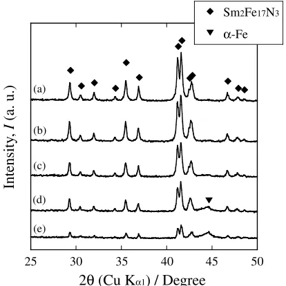
Figure 5 shows a cross-sectional brightfield image of the source powder and the powder annealed at 673 K for 180 s. One particle of the source powder is composed of a single crystal. The selected area diffraction (SAD) pattern obtained from the powder is indexed as a Th2Zn17structure. After heat
25 30 35 40 45 50
Sm2Fe17N3 α-Fe
Intensity
,
I
(a. u.)
2
θ
(Cu K
α1) / Degree
(a)(b)
(c)
(d)
(e)
[image:2.595.324.531.71.278.2]0 2 4 6 8 10 12 14
200 300 400 500 600 700 800 900 1000 BH max (400MPa) BH (100%)
Maximum ener
gy product,
BH
max
/ MGOe
Sintering Temperature, T / K
Powder
..
ρ = 68.6 %
72.4
79.1
82.6
Fig. 3 Change in maximum energy product as a function of sintering temperature. Solid circles indicate raw values and open circles indicate the calculated values for the sintered sample, assumed to have 100%relative density.
-15 -10 -5 0 5 10 15
-60 -40 -20 0 20 40 60
powder 573 K 873 K
Magnetization,
J
/ kG
Magnetic Field,
H
/ kOe
(a) (b)
0 2 4 6 8 10 12 14
0 2 4 6 8 10 12 14
200 300 400 500 600 700 800 900 1000 Br / kG
Hc / kOe
Residual Magnetization,
B
r
/ kG
Coerci
vity
,
H
c / kOe
Temperature,
T
/ K
source powder
Fig. 2 (a) RepresentativeJHcurves in raw powder and sintered samples. (b) Change in residual magnetization and coercivity as a function of sintering temperature.
0 0.5 1 1.5 2 2.5 3 3.5
200 300 400 500 600 700 800 900 1000
Nitrogen Content,
C
N
(mass %)
Sintering Temperature, T / K
Fig. 4 Change in nitrogen content in sintered sample as a function of sintering temperature.
003
110
e-// [110] -113
000 000
220 420
-240
-e-// [001]
(a)
(b)
200 nm
200 nm
[image:3.595.82.513.74.269.2] [image:3.595.325.527.316.509.2] [image:3.595.68.270.316.509.2] [image:3.595.115.483.573.760.2]treatment at 673 K, the particle maintained the Th2Zn17 structure, although the particle showed some strain and a corresponding contour pattern.
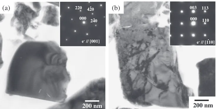
Enlarged images of the surface of the sample annealed at 673 K are shown in Fig. 6. For comparison, the surface of a particle in the source powder is also shown. A thin layer (³30 nm thick) is observed around the particle in the annealed sample. However, this thin layer is not observed in the source powder. The crystal structure of the annealed samples is characterized by a nanobeam diffraction pattern obtained from a region adjacent to the thin layer (site cA) and from the thin layer itself (site dA), shown in (c) and (d), respectively. Although the adjacent region has a Th2Zn17 structure, the crystal structure of the layer cannot be indexed as a Th2Zn17 structure. The SAD pattern obtained from the layer suggests that the symmetry of its crystal structure is higher than that of the adjacent region and is comprised of a cubic or simple hexagonal structure; however, the structure is not clarified in detail. Higher symmetric structures usually show a lower magnetic crystalline anisotropy. Therefore, the thin layer should have soft magnetic properties in contrast to the adjacent regions with the Th2Zn17 structure. Moreover, the layer shows coherency with the inner structure because the position of the SAD pattern obtained from the thin layer is the same as that obtained from
adjacent regions. From the above results, it can be inferred that the formation of the coherent thin layer is the reason for the introduction of strain in the particle. In other words, strain was introduced because the coherent layer constrained the inner structure of the particle without the generation of dislocations at the boundary between the layer and the adjacent region. The introduction of a strainfield in a matrix by the formation of a coherent precipitate is frequently observed in metals. Thus, the formation of a thin layer is an adequate reason for the introduction of strain, as observed in Fig. 5(b).
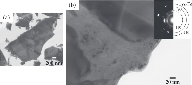
[image:4.595.114.483.69.235.2]A TEM image of the sample annealed at 873 K is shown in Fig. 7. Irregular growth of the nanostructured thin layer is seen in this figure. However, the contour pattern resulting from the strain observed in Fig. 5(b) cannot be seen. Internal strain accelerates atomic diffusion in a certain direction. Thus, irregular grain growth that minimizes the strain energy can occur. Therefore, the irregular growth observed in this study is caused by the effect of internal strain, resulting in the relaxation of strain. From the SAD pattern, it can be observed that the growth layer contains an ¡-Fe phase. This result implies that the thin layer seen in the sample annealed at 673 K appears to be¡-Fe or a precursor for iron formation. This layer was too thin to be detected by XRD, and so the XRD pattern did not change with sintering up to 773 K.
(a)
(b)
20 nm
20 nm
(c)
(d)
c’
d’
Fig. 6 Enlarged images of surface of (a) source powder and (b) powder annealed at 673 K for 180 s. (c) and (d) are SAD patterns obtained from site cAand dA, respectively.
(a)
(b)
20 nm 200 nm
110 200
210
α-Fe
[image:4.595.114.481.282.444.2]As established previously, the magnetization reversal mechanism of Sm2Fe17Nx is controlled by nucleation.11) In
this mechanism, the nucleation of the reverse magnetic domain is governed by nanoscale inhomogeneity at a grain boundary or particle surface.1214) The Sm2Fe17N3 powder used in this study was composed of single grains; hence, nucleation in the powder occurs at the powder surface. The thin layer should have soft magnetic properties as mentioned above. Therefore, the nucleation of a reverse magnetic domain is easily achieved at the particle surface, in contrast to the powder without the thin layer. Furthermore, the boundary between the thin layer and the inner particle having a Th2Zn17 structure shows a coherency, which indicates that the domain wall motion of a reverse magnetic domain from the thin layer to the inner region of a particle can occur without the pinning effect from the grain boundary. Therefore, the formation of a thin layer should cause a reduction in coercivity below the decomposition temperature.
5. Conclusion
Sm2Fe17N3 powders were consolidated at temperatures of 573 to 873 K under 400 MPa. The residual magnetization, coercivity, and maximum energy product decreased with an increase in the sintering temperature even though phase decomposition was not observed in samples sintered between 573 and 673 K. This can be explained by the formation of a thin layer surrounding the Sm2Fe17N3 particle. The thin layer showed a coherency with the inner Sm2Fe17N3phase, and thus a strain field was introduced in the powder. This layer was inferred to possess soft magnetic properties, and
it thus acted as a nucleation site for a reverse magnetic domain, thereby resulting in the reduction in coercivity. Irregular growth of the thin layer was observed in powder annealed at 873 K. The irregular growth was attributed to the relaxation of the strain field introduced by the formation of the thin layer, and the grown region was indexed as an iron phase.
REFERENCES
1) J. M. Coey and H. Sun:J. Magn. Magn. Mater.87(1990) L251L254. 2) T. Iriyama, K. Kobayashi, N. Imaoka, T. Fukuda, H. Kato and Y.
Nakagawa:IEEE Trans. Magn.28(1992) 23262331.
3) C. N. Christodoulou and T. Takeshita:J. Alloy. Compd.202(1993) 173182.
4) N. Imaoka, T. Iriyama, S. Ito, A. Okamoto and T. Katsumata:J. Alloy. Compd.222(1995) 7377.
5) A. Chiba, K. Hokamoto, S. Sugimoto, T. Kozuka, A. Mori and E. Kakimoto:J. Magn. Magn. Mater.310(2007) e881e883.
6) T. Saito, M. Fukui and H. Takeishi:Scr. Mater.53(2005) 11171121. 7) D. T. Zhang, M. Yue and X. Zhang:Powder Metall.50(2007) 215
218.
8) K. Takagi, H. Nakayama, K. Ozaki and K. Kobayashi:J. Magn. Magn. Mater.324(2012) 13371341.
9) K. Takagi, H. Nakayama and K. Ozaki:J. Magn. Magn. Mater.324 (2012) 23362341.
10) A. Kawamoto, T. Ishikawa, S. Yasuda, K. Takeya, K. Ishizuka, T. Iseki and K. Ohmori:IEEE Trans. Magn.35(1999) 33223324.
11) X. C. Kou, W. J. Qiang, H. Kronmüller and L. Schultz:J. Appl. Phys. 74(1993) 67916797.
12) H. Kronmüller, K.-D. Durst and M. Sagawa:J. Magn. Magn. Mater.74 (1988) 291302.
13) T. Fukagawa, S. Hirosawa, T. Ohkubo and K. Hono:J. Appl. Phys.105 (2009) 07A724.