Abstract—Hybrid systems are used in engineering systems and scientific applications to enhance and to improve their efficiency. This paper presents a hybrid system using digital signal processing (DSP) systems and artificial neural networks (ANN’s) for object motion detection, extraction and filtering. A summary of a DSP motion detection system is first presented and its performance is compared to that of an ANN ensemble system (AES). The two systems are then combined to form a hybrid motion detection system. Preprocessing of the hybrid system uses wavelet image compression to enhance its computational speed. During the testing of the system the efficiency of the (AES) is demonstrated as a powerful parallel processor in handling large amounts of image data.
Index Terms—artificial neural networks, digital signal processing, hybrid, wavelet transforms
I. INTRODUCTION
Ybrid systems have been used extensively in computational intelligent paradigms to solve technical tasks. They have become powerful approaches in solving real-life engineering problems and to improve the overall efficiency of systems [22], [23]. Computational intelligent paradigms such as artificial neural networks (ANNs) have an advantage in that they can be combined with other conventional methods such as signal processing (SP), digital signal processing (DSP) and image compression processing to optimize and improve the processing of imaging systems [11], [12], [13].
Hybrid systems combine strengths and suppress weakness of each system when combined. Hybrid approaches have a special status in image processing systems as they can combine different approaches in either serial or parallel configurations in order to overcome the shortcomings of the individual image processing system components of combined systems [24], [25].
This paper proposes a hybrid motion detection system which uses wavelet image compression as preprocessing, DSP algorithms for motion detection in stage 1 and an ANN ensemble system object extraction and filtering in stage 2 of the system. ANN systems are immune to noise and can handle changes in input data and channel noise more robustly, this characteristic compensates for the problematic filtering that the DSP systems cannot overcome [5], [7].
Manuscript received 1 December 2012; revised 8 January 2013. The work was supported by the Durban University of Technology.
First Author: Department of Electronic Engineering, Durban University of Technology, South Africa, Email: [email protected]
Second Author: Department of Electronic Engineering, Durban University of Technology, South Africa, Email: [email protected].
DSP systems have the added advantage of higher computational speeds than the ANN systems [12]. The proposed hybrid system exploits these advantages to produce an improved system for object motion detection, extraction and filtering.
This paper is arranged as follows: section 2 describes the architecture of the proposed Hybrid Motion Detection System which uses DSP, ANN ensembles and wavelet image compression; section 3 discusses the wavelet transforms used for image compression; section 4 presents the experimental results of the DSP system vs the AES, the hybrid motion detection system and section 5 concludes the study.
II. HYBRID MOTION DETECTION DESIGN
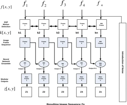
The first approach illustrated in Fig 1(a) is the parallel approach which is adapted to the image data where the input to the system is presented with parallel image data followed by a final parallel output of image data. The second approach is shown in Fig 1(b), which is the serial input of image data where output data from one system is serially transferred to the next stage with the serial output of image data[30], [33] ] , [ ] , [ ] , [ ) 2 ( ] , [ ] , [ ] , [ ) 1 ( ] , [ ] , [ ] , [ 2 1 2 1 2 1 y x z y x z y x z Stage y x k y x k y x k Stage y x f y x f y x f (a) ]} , [ ]; , [ ];....; , [ { } ) 2 ( { ]} , [ ]; , [ ...; ]; , [ { )} 1 ( { ]} , [ ; ] , [ ..., ]; , [ { 1 2 1 2 1 2 y x z y x z y x z Stage y x k y x k y x k Stage y x f y x f y x f (b)
Fig1: Hybrid System Configurations (a) Parallel Scheme (b) Serial Scheme
With regards to Fig 1(a) and (b),
f
[
x
,
y
]
represents the input image data,k
[
x
,
y
]
the image data transfer between stage 1 and stage 2, andz
[
x
,
y
]
is the data at the output of the hybrid system. The image frames are 2-D image functions having x – rows and y – columns. Both the hybrid schemes shown in fig 1 were tested for this study. Each image framef
[
x
,
y
]
consisted of 256 x 256 pixel points for a standard image.Hybrid Motion Detection System Using DSP
and ANN Ensembles
Kevin Emanuel Moorgas and Poobalan Govender
A. The Serial Hybrid Scheme
During testing the serial scheme proved unreliable because the large image data of each frame and the loading of consecutive frames which comprised an image sequence. The captured video sequence had to be presented serially to the input of the model; this caused congestion at the input channel to this hybrid model because the image frames were not being processed fast enough due to the hardware constraints of the system. No results were obtained during this testing. The parallel hybrid scheme offered a better solution in that a number of image frames could be presented to an input simultaneously in a parallel configuration as shown in fig 2.
B. The Parallel Hybrid Scheme
The parallel hybrid scheme consisted of a DSP system in stage 1 for object motion detection, while the ANN system was configured as an ensemble of neural networks (NN) for image filtering and extraction in stage 2. Fig 2 is a detailed description of the parallel hybrid motion detection system.
Frame 1
Frame 2
Frame 3
Frame 4
Nth Frame
NN 1
NN
2 NN
3
NN
4 Nth NN
New Frame 1
New Frame 2
New Frame 3
New Frame 4
1 2 3 4
Resulting Image Sequence Zn
Neural Network Ensamble
Modular Outputs
Output 1 Output 2 Output 3 Output 4 Output N-1
Image Frame Sequence
In
tr
o
d
u
c
tio
n
o
f N
o
is
e
New Frame n
Z1 Z2 Z3 Z4 Zn
DSP Motion Detection
k1 k2 k3 k4 kn
1
f
f
2] , [xy f
] , [xy k
] , [x y z
3
f
f
4 fnFrame 1
Frame 2
Frame 3
Frame 4
[image:2.595.49.291.302.502.2]Nth Frame
Fig 2: Hybrid Motion Detection System
B. The DSP System
For this study the DSP motion detection system was implemented in stage 1 of the hybrid system. The 2-D Discrete Fourier Transform (DFT) (1) algorithm that is used for image processing operations is applied. The high frequency components of the 2-D image can be represented using the DFT which represents sharp variations, or edges, in pixel gray levels that occur along the borders or within the texture of an image indicating the position of an object within the image. Where the pixel intensity changes rapidly it indicates the boundary and high frequencies of the DFT [4], [14]. The pixel intensity of an object and its edges is what identifies a region of interest (ROI) from its background [26].
10 1
0
]
)
(
2
exp[
]
,
[
1
)
,
(
N
y N
x
N
vy
ux
j
y
x
f
N
v
u
F
(1)u, v = 0,1,2, …, N – 1
With regards to (1): u and v denotes the frequency variables; f [x, y] is a square M x N digital image matrix and the frequency components of a grey scaled image frame square matrix
f
[
x
,
y
]
, with α representing the frame number. The DSP motion detection system was designed to detect moving objects by image subtraction [26]. Image subtraction is used widely in image processing to segment dynamic regions from static regions for higher level processing of images for motion detection, recognition and object tracking [26], [14]. The method of image subtraction was applied as follows: background subtraction and temporal differencing as described in [26] and [14]. (2) represents background subtraction which removed the background leaving only the ROI where the change in pixel intensity indicated motionƒα [x, y] – Bα = Gα (2)
where matrix B denotes the static background, G is the cluster of pixels of the ROI and α indicates the number of the captured frame. This motion can be shown as the pixel intensity of G in any captured frame ƒα [x,y]. Temporal
differencing is applied to each successive frame following background subtraction. The extracted ROI frame becomes the new image frame (3):
ƒr [x, y] = ƒα [x, y] – Bα (3)
With regards to (3): ƒr [x, y] is the resulting new frame
following background subtraction, where r denotes the frame number and α indicates the number of the captured frame. (4) was used for temporal differencing.
Kd1=|K1-K2|, Kd2=|K2-K3|,…,Kdnth=|Kn-1-Kn| (4)
With regards to (4), each K-matrix is subtracted from its preceding matrix. The difference between the two corresponding image matrix values is converted into an absolute value and stored in a difference matrix Kd to
eliminate negative values. This process is continued for all images in the frame matrix. Motion mask U shown in (5) was obtained after background subtraction.
motion
no
K
U
d0
0
1
(5)
U is applied to each successive difference matrix Kd and
results in image matrix sequence K2 (6).
K2 = Kd1, Kd2, …,Kdnth (6)
C. The ANN Ensemble System
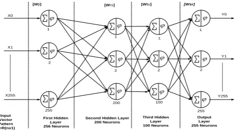
X0 X1 X255 Input Vector Pattern X=R(nx1) First Hidden Layer 256 Neurons
Second Hidden Layer 200 Neurons Third Hidden Layer 100 Neurons Output Layer 255 Neurons Y0 Y1 Y255
[Wji] [Wrs] [Wtu] [Wsr]
[image:3.595.57.288.49.178.2]1 2 255 1 2 200 1 2 100 1 2 255
Fig 3: Architecture of a Neural Network (NN)
ANN systems can process large amounts of data accurately and contribute towards eradicating errors and noise [2]. The generalization performance of a neural network system was improved by using an ensemble of similarly configured ANNs as described in [7], [15].
The ANN system designed for this study is comprised of a single layer of multiple NN connected in a parallel configuration. The output of the DSP system of stage 1 of the hybrid system was the input to the AES. Fig. 3 shows the architecture of the NNs used in the hybrid system. The NNs consisted of an input layer with 256 inputs, two hidden layers with each layer having 100 neurons and 200 neurons, respectively and an output layer consisting of 256 outputs. This configuration of NNs ensured a high resolution by mapping each of the pixel points of the DSP image frames to the output of the hybrid system. The AES uses multilayer feedforward (MLFF) backpropagation networks and a log-sigmoid nonlinear activation function.
III. WAVELET IMAGE COMPRESSION
Wavelet transforms decomposes an image signal on a set of bases functions called “wavelet”. The Discrete Wavelet Transform (DWT) is related to multi rate signal processing techniques similar to DSP [20], [21]. The basis functions are obtained from a single “wavelet mother” by dilations and scaling. Wavelet image compression is used as a preprocessor to improve the computational speed of the hybrid system [27]. For this study, the Haar, Daubechies (db4) and biorthogonal (bior 1.3) wavelets were used as image compression preprocessing algorithms to test the Hybrid system with the objective of reducing the detection time of the hybrid motion detection system.
A. The 2D – Wavelet Transform
The 2D-DWT is defined by (7) and (8) for the image frames within the image frame sequencesf[x,y] of size M x N.
) , , (j mn
W are coefficients defined as approximations of ]
, [x y
f with j0 the starting scale. The
) , , (j mn
Wi coefficients add horizontal, vertical and diagonal details for scales j. N=M=2j so that j = 0, 1, 2, …, j – 1 and m = n = 0, 1, 2, …, 2j – 1.
1 0 1 00 [ , ] , , ( , )
1 ) , , ( M x N y
j m n x y
y x f MN n m j
W
(7)
1 0 1 0 ) , ( , , ] , [ 1 ) , , ( M x N y i j i y x n m y x f MN n m jW
(8)A captured image frame f[x,y]contains a vector space
j
V
which has2
jpixels inV
j with j = 0, 1, 2 ….n-1. B. Haar Wavelet CompressionThe Haar wavelet is used for most image processing applications because of its simple algorithm, high compression processing time and compactness [3], [17], [19]. (9) is the conventional 2D Haar wavelet scaled and translated box functions.
j( ): (2j ) 0,1,2...2j1
i x
x i wherei
(9) otherwise x for
x 0 1
0 1 ) (
The Haar wavelets corresponding to the box basis are given by (10): 1 2 ... 2 , 1 , 0 ) 2 ( : )
( j j
j
i x
x i wherei
(10) otherwise x for x for x 0 1 2 / 1 1 2 / 1 0 1 : ) (
C. Daubechies Wavelet Compression
Daubechies’ wavelets are used in image analysis and synthesis because they are orthonormal, have continuous derivatives (images are smooth except occasional edges) and compact algorithms [18], [20]. The Daubechies’ wavelets have quadratic mirror filters of the Haar wavelet. Like the Haar wavelet the Daubechies’ wavelet was translated for any image frame f[x,y]within the captured sequence.
D.. Biorthogonal Wavelet Compression
Biorthogonal Wavelets exhibit properties of linear phase which is needed for signal and image reconstruction and analysis [1]. They are excellent for image coding and de-noising [9],[16]. Many elegant quantization and entropy coding techniques have been developed that exploit the multi-resolution nature of this wavelet family to enhance the low bit rate coding of images [18]. The properties of the biorthogonal wavelets have duality in any subspace because of its symmetry and separate decomposition and reconstruction functions in each member of its family of wavelets [28], [29]. The scaling functions are obtained by multiplication for a vector space
V
j which can be translated to an image matrix frame f[x,y].IV. EXPERIMENTAL RESULTS
In this section we discuss the results obtained from the DSP system, the ANN system and the Hybrid Systems as motion detectors.
A. DSP Motion Detector
(a)
(b)
(c)
(d)
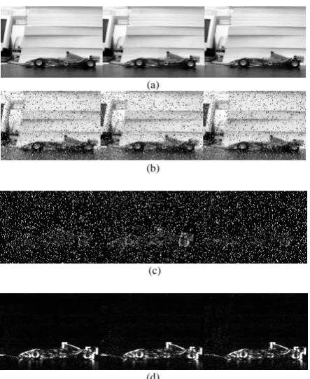
Fig 4: DSP Motion Detection, (a) Captured Image Sequence (b) Induced Noise Salt & Pepper at 0.09 (c) DSP Motion Detection and Extraction (d) Median Filtered and Enhanced Image Sequence
B. ANN Motion Detector
The ANN system shown in fig 2 was configured as a motion detection system with the DSP stage bypassed. Image sequence frames were presented to the input of each neural network from
n
NN to
NN1 is depicted in fig 2. Fig. 5(a) represents the image sequence used in the NN and is similar to that used for the DSP motion detection system. Each gray scaled 256 x 256 image frame matrix is first normalized to the range [0, 1] for faster convergence of the target during training before being applied into the network [6], [8], [15]. Each subsequent frame forms the target for the preceding NN for motion detection. Image frame sequence Ka (11) are
presented to the ANN system.
Ka = (K'1, K'2,……K'nth) (11)
The ANN’s behave as a motion detecting ensemble to indicate the new position of the object. The output is represented by Z (12) Fig 5(c).
(a)
(b)
(c)
[image:4.595.59.281.46.317.2](d)
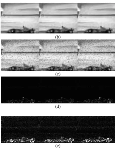
Fig 5: ANN Motion Detection and Filtering: (a) Captured Image Sequence (b) Induced Noise Salt & Pepper at 0.09 (c) ANN Motion Detection, Filtering and Image Extraction (d) Image Enhancement
Z = (Z'1, Z'2,……..,Z'nth ) (12)
In order to standardize the end processing for comparison Fig 5(d) is enhanced as in Fig 4(d) of the DSP detector system to ensure the validity of the comparison between the ANN and DSP systems.
Comparative Peak Signal to Noise Ratio (PSNR) responses of the DSP Motion Detection system vs the ANN Motion Detection System are presented in Fig 6. Fig 6 shows that the AES has a superior PSNR response than the DSP. With regard to Fig. 6 the PSNR are shown as follows:
C. Comparing the DSP vs ANN Motion Detector Image Sequence 1, captured image sequence:
Under identical conditions for each motion detection test (Fig. 4(a) and Fig. 5(a)).
Sequence 2, noise is induced:
For each image frame within the sequence 0.09 salt & pepper is induced (Fig. 4(b) and Fig. 5(b)).
Sequence 3, motion detection:
(Fig.4(c) DSP motion detection and extraction and Fig. 5(c) AES motion detection, object extraction and filtering).
Sequence 4, image enhancement:
Image frames of each sequence is enhanced for comparison (Fig. 4(d) and Fig. 5(d)).
Noise com parison of AES vs DSP Motion Detection
10 15 20 25 30
1 2 3 4
Im age Fram e Sequences
P
S
N
R
(
d
B
)
AES DSP
Fig 6: PSNR of DSP System vs ANN Motion Detection System
[image:4.595.318.536.50.117.2] [image:4.595.307.545.478.622.2] [image:4.595.59.278.599.781.2]TABLE 1:
DSP vs ANN Ensemble Motion Detection (AES) Timing
D. Hybrid Motion Detection
The proposed hybrid system exploits the advantages of the DSP system and the AES to form a single system for improved motion detection object extraction and filtering. The results of the hybrid motion detection system using three wavelet image compression techniques as preprocessing are shown in Fig 7, Fig 8 and Fig 9. The compression algorithms were applied in order to improve the overall processing time for object motion detection and filtering. The wavelet image compression is applied as follows: Fig 7 Haar compression, Fig 8 Daubechies (db4) and Fig 9 biorthogonal (bior 1.3).
(a)
(b)
(c)
(d)
(e)
Fig 7: Motion Detection of the Hybrid AES using Haar Wavelet Compression (a) Captured Image Sequence (b) Image compression (c) Induced noise Salt & Pepper at 0.09. (d) Image motion detection and extraction (e) Image Enhancement
(a)
(b)
(c)
(d)
(e)
Fig 8: Motion Detection of the Hybrid AES using Daubechies Wavelet Compression (a) Captured Image Sequence (b) Image compression (c) Induced noise Salt & Pepper at 0.09. (d) Image motion detection and extraction (e) Image Enhancement
(a)
(b)
(c)
(d)
[image:5.595.78.265.318.667.2](e)
Fig 9: Motion Detection of the Hybrid AES using Biorthogonal Wavelet (a) Captured Image Sequence (b) Image compression (c) Induced noise Salt & Pepper at 0.09. (d) Image motion detection and extraction (e) Image Enhancement
DSP vs AES Timing
DSP Motion Detection
ANN Ensemble Motion
without noise 4.57s 6.55 min
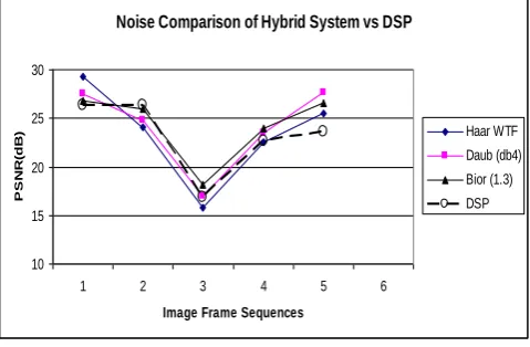
[image:5.595.322.531.354.717.2] [image:5.595.70.266.727.779.2]The (PSNR) responses of the Hybrid Motion Detection system vs the DSP system is presented in Fig 10 while Table 1 shows the timing of the systems. Fig 10 shows that the hybrid system has a superior PSNR response than that of the DSP system. With regard to Fig. 10 the PSNR are shown as follows:
E. Comparison of the DSP vs Hybrid Motion Detector Sequence 1, captured image sequences:
Under identical conditions for each motion detection test (Fig. 4 (a), Fig. 7(a), Fig. 8(a), and Fig. 9(a)).
Sequence 2, image frames are compressed:
For each image frame within the captured sequences different image compression methods are applied (Fig 4 (a), Fig. 7(b), Fig. 8(b) and Fig. 9(b)). Fig 4 (a) is repeated in this sequence because no image compression was applied to the DSP system.
Sequence 3, noise is induced:
The same level of noise is induced to each frame of each image sequence (Fig 4 (b), Fig. 7(c), Fig. 8(c) and Fig. 9(c)). Sequence 4, motion is detected:
Motion detection and object extraction (Fig 4(c), Fig. 7(d), Fig. 8(d) and Fig. 9 (d)). Noise is not removed in Fig 4 (c) of the DSP system.
Sequence 5, image enhancement:
Each frame of the image sequence is enhanced to show the new position of the non – stationary object (Fig 4 (d), Fig. 7(e), Fig. 8(e) and Fig. 9(e)).
Noise Comparison of Hybrid System vs DSP
10 15 20 25 30
1 2 3 4 5 6
Image Frame Sequences
P
S
N
R
(dB
) Haar WTF
[image:6.595.49.289.395.552.2]Daub (db4) Bior (1.3) DSP
Fig: 10. PSNR of the Hybrid System with DWT Image Compression
[image:6.595.46.293.618.703.2]Preprocessing
TABLE 2
Hybrid Motion Detection Timing with Image Compression
Hybrid AES Motion Detection
Timing
Haar Image Compression Preprocessing
Daub (db4) Image Compression Preprocessing
Bior 1.3 Image Compression Preprocessing
without noise 2.11mins 2.56 mins 2.01 mins
with induced noise
2. 47 mins 3.17mins 3.48 mins
Table 2 shows the average processing time of the Hybrid Motion Detection System. With regards to table 1 and table 2, there is improved processing time with applying the hybrid motion detection system. When considering the image compression preprocessing applied to the image sequences of the hybrid system, the Haar exhibits the fastest
average processing time, followed by Bior (1.3), then Daub (db4).
V.CONCLUSION
This paper showed that the hybrid motion detection system used for object detection, extraction and filtering had improved processing time and still retained high image quality with image compression preprocessing methods. The method of object motion detection, extraction and filtering presented proved superior to the conventional DSP motion detection system. The DSP system displayed faster processing time than the ANN motion detection system as shown in table 1, but the hybrid system performed better by producing better image quality sequences shown in Fig 10. A major contributing factor to the slow processing time of the hybrid system was as a result of the hardware constraints of the computer systems which initially did not provide reliable results when applying the serial hybrid scheme but provided reliable results in the parallel scheme.
ACKNOWLEDGMENT
This work is supported by the Durban University of Technology.
REFERENCES
[1] Alam M., Badawy W., Dimitrov V. and Jullien G., “An Efficient
Architecture for Lifted 2D Biorthogonal DWT”, Journal of VLSI Signal Processing 40, 335-342, 2005, Springer Science + Business Media, Inc.
[2] Bitten J.R. and Dr. Osorio F.S., “Adaptive Filters for Image
Processing based on Artificial Neural Networks”, Proceedings of the Brazilian Symposium on Computer Graphics and Image Processing,
IEEE (SIBGRAPI ’00). ISBN 0-7695-0878-2/00, 2000.
[3] Elfouly F.H., Mahmoud M.I., Dessouky I.M., and Deyab S.,
“Comparison Between Haar and Daubechies Wavelet
Transformations on FPGA Technology”, International Journal of Computer Information, Systems Science, and Engineering 2;1
WASET 2008.
[4] Gonzalez R.C. and Woods R.E., “Digital Image Processing”, Pearson
Prentice Hall, Third Edition, Published 2008.
[5] Govender P., Singh R., Paramanund C., Naicker A., Bright G.,
“Industrial Quality Assurance Using Artificial Intelligence”, Published, 2006.
[6] Hagan M.T., Demuth H.B., and Beale M.H., “Neural Network
Design”, Boston, MA: PWS Publishing,1996.
[7] Hansen L.K. and Salamon P., “Neural Network Ensembles”, IEEE
Transactions on Pattern Analysis and Machine Intelligence, Vol. 12, Number 10, pp 993- 1001, 1990.
[8] Ham F.M. and Kostanic I., “Principles of Neurocomputing for
Science and Engineering”, Mc Graw Hill, Published, 2001.
[9] Khare A. and Tiwary U.S., “Daubechies Complex Wavelet Transform
Based Technique for Denoising of Medical Images”, International Journal of Image and Graphics, Vol 7, No.4 (2007) 663-687, World Scientific Publishing Company.
[10] Liu M., Jiang X., Kot A. C., “Nonlinear Fingerprint Orientation
Smoothing by Median Filter”, IEEE Information, Communications
and Signal Processing, Fifth International Conferernce, Vol. Issue 2005 pp 1439-1443.
[11] Moorgas K.E. and Govender P., “DSP Systems vs ANN Ensembles
for Motion Detection and Filtering”, Conference Proceedings, World Congress of Engineering and Computer Science, WCECS 2008, pp 1129-1134.
[12] Moorgas K.E., “Image Compression Preprocessing for ANN
Ensemble Motion Detection System”, Conference Proceedings, World Congress on Engineering, Vol 1, WCE 2010, pp 720 - 725
[13] Menegaz G., “Trends in Medical Image Compression”, Current
Medical Imaging Reviews, 2, 165-185, Bentham Science Publishers Ltd, 2006.
[14] Najarian K., and Splinter R., “Biomedical Signal and Image
[15] Polikar R., “Ensemble Based Systems”, IEEE magazine circuits and systems 2006, 1531-636X/06/. pp 21 – 45.
[16] Pragada S. and Sivaswamy J., “Image Denoising Using Matched
Biorthogonal Wavelets”, Sixth Indian Conference on Computer
Vision, Graphics & Processing, 978-07695-3476-3/08, 2008 IEEE, DOI 10.1109/ICVGIP.2008.95.
[17] Raviraj P. and Sanavullah M.Y., “The Modified 2D - Haar Wavelet
Transformation in Image Compression”, Middle-East Journal of Scientific Research 2 (2) 73-78, 2007, ISSN 1990-9233, IDOSI Publication, 2007.
[18] Riazifar N. and Yazdi M., “Effectiveness of Contourlet vs Wavelet
Transform on Medical Image Compression: A Comparative Study”, Proceedings of World Academy of Science, Engineering and Technology (PWASET) Vol. 37, January 2009 ISSN 2070-3740.
[19] Talukder K.H. and Harada K., “Haar Wavelet Based Approach for
Image Compression and Quality Assessment of Compressed Images”, IAENG International Journal of Applied Mathematics, 36:1, IJAM 36 1 9, Online publication 1 February 2007.
[20] Hilton M.L., Jawerth B.D. and Segupta A., “Compression Still and
Moving images with wavelets”, Mutimedia Systems, Springer-Verlag(1994) 2:218-227.
[21] Hosam K. et al, “Three – Dimensional Video Compression Using
Subband/Wavelet Transform with Lower Buffering Requirements”,
IEEE Transactions on Image Processing, Vol. 8, No. 6, pp 762-773
1999.
[22] McGarry K., Wermter S., and MacIntyre J. “Hybrid Neural Systems:
From Simple Coupling to Fully Integrated Neural Networks”, Neural Computing Surveys 2, 62-93, 1999, Available pp1 -32
http://www.icsi.berkeley.edu/~jagota/NCS
[23] Bodyansky Y., and Dolotov A., “Hybrid Systems of Computational
Intelligence Evolved From Self-Learning Spiking Neural Networks”, Methods and Instruments of Artificial Intelligence, ITHEA, 2009 pp 17 – 24.
[24] Nes A. “Hybrid Systems for Face Recognition”, Master’s Thesis,
Dept of Computer and Information Science, Norwegian University of Science and Technology, Norway, 2003.
[25] Peddabachi S. et al, “Modelling Intrusion Detection Using Hybrid
Intelligent Systems”, Science Direct Journal of Network and Computer Applications 30 (2007), pp 114 – 132.
[26] Desa S.M. and Salih Q. A., “Image Subtraction for Real Time Object
Extraction” IEEE, Proceedings of International Conference on Computer Graphics, Imaging and Visualization, pp 26 – 35, 2004.
[27] Antonini M., Barlaud M., Mathieu P., and Daubechies I., ‘Image
Coding Using Wavelet Transform’, IEEE Trans. Image Processing
Vol. 1. NO 2, April 1992, pp 205 - 220.
[28] Wang J.Z., Wiederhold G., Firschein O. and Wei S. X., “Content –
based Image Indexing and Searching Using Daubechies’ Wavelets.”, Digital Libraries, Springer – Verlag (1997) 1:311-328.
[29] Winger L.L. and Venetsanopoulos A.N., “Biorthogonal Nearly Coiflet