Design and Analysis of Reduced Harmonic
Multi-Level Inverter for Solar Integrated Grid Connected
System
K. Prasanna Kumari1, Ch.Venkata Suresh2
1
M-tech Student Scholar Department of Electrical & Electronics Engineering VVIT Engineering College, Nambur; Guntur (Dt); A. P, India.
2
Professor Department of Electrical & Electronics Engineering VVIT Engineering College, Nambur; Guntur (Dt); A.P, India.
Abstract: This project proposes a single-phase Three-level, five-level and seven-level inverter for PV grid-connected photovoltaic systems, with a pulse width-modulated (PWM) control scheme. Three reference signals that are identical to each other with an offset that is equivalent to the amplitude of the triangular carrier signal were used to generate the PWM signals. The inverter is capable of producing seven levels of output-voltage levels from the dc supply voltage. Multilevel inverter performance is compared with three level inverter, five level and seven level inverters to reduce their harmonic distortion and by increasing levels with reduced number of switches losses are decreased and harmonics are eliminated. This project presents the cascaded H-bridge multilevel inverters for single phase PV grid connected system and their effects on grid current. Any carrier based PWM is applicable for cascaded H-bridge (CHB). An advanced grid connected PV system consists of PV panel, Single phase three level, five level and seven level inverter, grid side control. The main objective of this paper is to get the reliable and stable output of modular grid connected photovoltaic generation system with single phase seven level inverter topology. It is obtained by using MATLAB software.
Keywords: Multi level inverter; SPWM; harmonic analysis; power electronics;
I. INTRODUCTION
A single-phase grid-connected inverter is usually used for residential or low-power applications of power ranges that are less than 10kW [1]. Types of single-phase grid-connected inverters have been investigated [2]. A common topology of this inverter is full-bridge three-level. The three-level inverter can satisfy specifications through its very high switching, but it could also unfortunately increase switching losses, acoustic noise, and level of interference to other equipment. Improving its output waveform reduces its harmonic content and, hence, also the size of the filter used and the level of electromagnetic interference (EMI) generated by the inverter’s switching operation [3].
Multilevel inverters are promising; they have nearly sinusoidal output voltage waveforms, output current with better harmonic profile, less stressing of electronic components owing to decreased voltages, switching losses that are lower than those of conventional two-level inverters, a smaller filter size, and lower EMI, all of which make them cheaper, lighter, and more compact [4].
Various topologies for multilevel inverters have been proposed over the years. Common ones are diode-clamped, flying capacitor or multi cell, cascaded H-bridge, and modified H-bridge multilevel. This paper recounts the development of a novel modified H-bridge single-phase multilevel inverter [5] that has two diode embedded bidirectional switches and a novel pulse width modulated (PWM) technique.
Grid connected photovoltaic (PV) converters represent the most widespread solution for residential renewable energy generation. While classical designs of PV converters feature a grid frequency transformer, which is a typically heavy and costly component, at the interface between the converter and the electrical grid, researchers are now considering transformer less architectures in order to reduce costs and weight and improve efficiency.
synthesize the output voltages using more levels, multilevel converters outperform conventional two and three-level converters in terms of harmonic distortion. Moreover, multilevel converters subdivide the input voltage among several power devices, allowing for the use of more efficient devices. Multilevel converters were initially employed in high-voltage industrial and power train applications. They were first introduced in renewable energy converters inside utility-scale plants, in which they are still largely employed [10]–[12]. Recently, they have found their way to residential-scale single-phase PV converters, where they currently represent a hot research topic.
II. CASCADED H-BRIDGE MULTILEVEL INVERTER
Cascaded H-bridge (CHB) multilevel inverter is one of the popular topology for converter used in high power medium voltage drives. It contains multiple units of single phase H-bridge power cells. The H-bridge cells are normally connected in cascaded on its ac side to achieve low harmonic distortion and medium voltage operation. In practice, the number of power cells in a CHB inverter is mainly determines by its operating voltage and the cost required for manufacturing. The CHB multilevel inverter requires a number of isolated dc supplies each of which feeds an H-bridge power cell [3]. The number of voltage levels in a CHB inverter can be found from
(1) Where H is the number of cells per phase leg in H-bridge. For the CHB inverter, voltage level m is always an odd number while in other multilevel topologies like diode-clamped inverters it can have either an even or odd number of levels. Any carrier based PWM schemes can be used for CHB inverter. The carrier based modulation schemes for multilevel inverter can be classified in two categories as follows
A. level Shifted Multicarrier Modulation
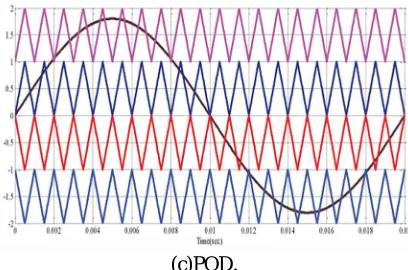
The level shifted modulation scheme requires (m-I) triangular carriers for m level CHB inverter, all the carriers have the same frequency and the same amplitude. The (m-I) triangular carriers are vertically placed such that the bands forms by the carriers are contiguous. Following figure shows three schemes for the level shifted multicarrier modulation. (a) in-phase disposition (IPD), where all carriers are in phase; (b) alternative phase opposite disposition(APOD), where all carriers are alternatively in opposite disposition; and (c) phase opposite disposition(POD), where all carriers above the zero reference are in phase but in opposition with those below the zero reference.
(a)IPD.
(c)POD.
Fig. 1. Level shifted PWM the frequency modulation index is given by
(2)
Which remains the same as that for the phase shifted modulation scheme whereas the amplitude modulation index is defined as V,
(3) Where Vm is peak amplitude of the modulating wave Vm and Vcr is the peak amplitude of each carrier wave.
B. Phase shifted Multicarrier Modulation
In general, a multilevel inverter with m voltage levels requires (m-l) triangular carriers. In the phase shifted multicarrier modulation, all the triangular carriers have the same frequency and the same peak to peak amplitude, but there is a phase shift between any two adjacent carrier waves, given by
(4)
The modulating signal is usually a three phase sinusoidal wave with adjustable amplitude and frequency. The gate signals are generated by comparing the modulating wave with carrier waves.
Fig. 2. Phase shift PWM for seven-level inverter.
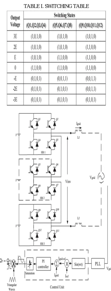
[image:3.612.195.422.462.617.2](5) TABLE I. SWITCHING TABLE
In this Phase locked loop (PLL) is used to synchronies the grid frequency with the supply frequency which makes the grid voltage and grid current are in phase with each other as shown in simulation result section. The Lf is the current limiting filter to limit the grid current. The current limiting inductor Lf is given by
(6)
Where VDC is the DC voltage of the inverter, Is", is switching frequency of the inductor and MLmax is ripple current of the inductor. The feedback current controller is used for this application. In this PI algorithm, Ire fis generated by comparing grid voltage with the reference voltage. Ire f is then multiplied by the output of PLL to generate 19ridre/- The current injected into the grid known as grid current Ignd, was sensed and fed back to a comparator that compared it with the reference current 19ridre/ The error from the comparison process of 19nd and Igridref was fed into the PI controller. The output of the PI controller, also known as Vref, being compared with the triangular wave to produce the switching signals for Q,-Q'2'.
III. MATLAB/SIMULINK RESULTS
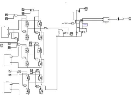
Fig 4 Circuit diagram of Cascaded Seven level Inverter for single phase Grid Connected System.
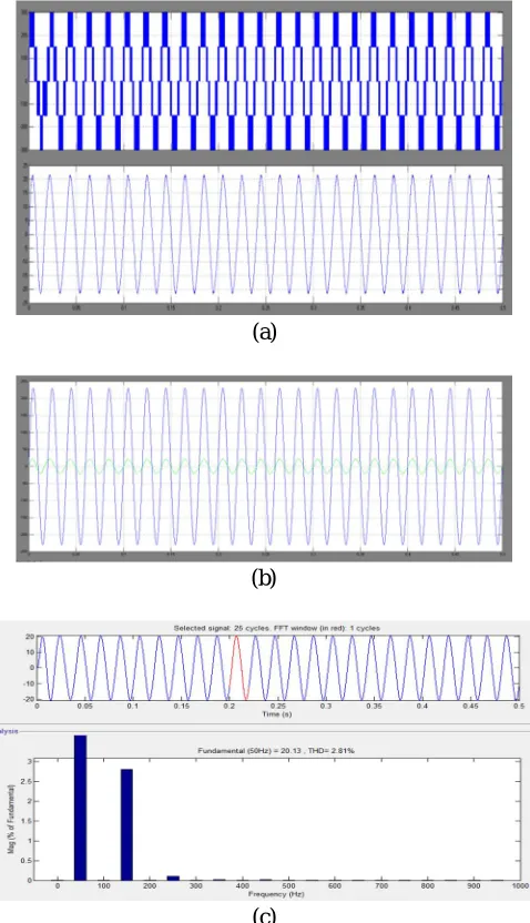
(a)
(c)
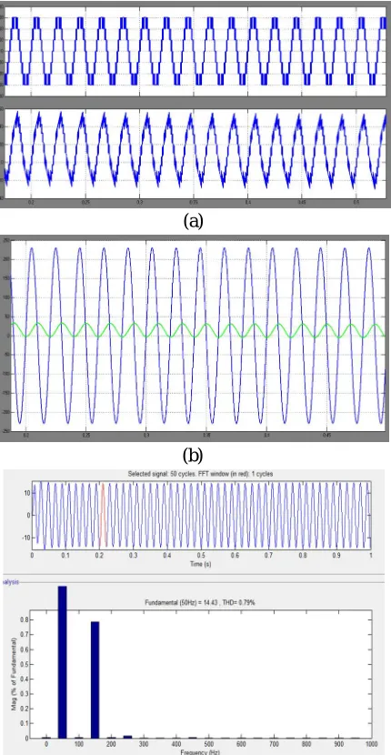
Fig, 5.(a) Three level Output voltage of inverter (b) In phase waveform of grid voltage and grid current (c)Harmonic Analysis of Grid Current.
(a)
(b)
(c)
[image:6.612.196.420.76.236.2] [image:6.612.187.426.279.695.2](a)
(b)
(c)
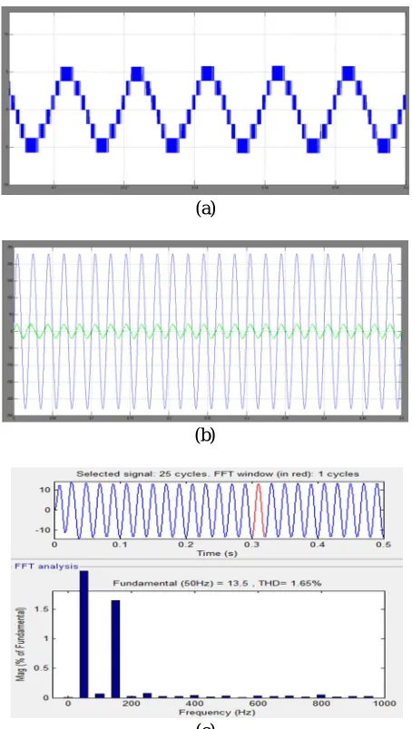
Fig 7(a) seven level Output voltage of inverter (b) In phase waveform of grid voltage and grid current (c) Harmonic Analysis of Grid Current. Fig
[image:7.612.193.420.74.476.2](a)
(b)
(c)
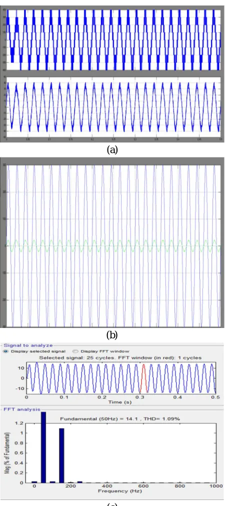
Fig 9 (a) five level PV Output voltage of inverter (b) In phase waveform of grid voltage and grid current (c) Harmonic Analysis of Grid Current.
.
[image:8.612.192.419.549.714.2](a)
(b)
Fig 11 a) seven level PV Output voltage of inverter (b) In phase waveform of grid voltage and grid current (c) Harmonic
Analysis of Grid Current.
[image:9.612.200.415.77.492.2](a)
(b)
(c)
Fig 13(a) nine level Output voltage of inverter (b) In phase waveform of grid voltage and grid current (c) Harmonic Analysis of Grid Current.
IV. CONCLUSION
[image:10.612.194.419.72.578.2]The harmonic analysis of grid current is carried out for different levels. From the analysis it is clear that as the number of levels increases the %THD decreases. So multilevel inverter is used for grid connected system to inject less harmonic current to the grid.
REFERENCES
[1] N. A. Rahim, K. Chaniago, and l. Selvaraj, "Single-Phase Seven-Level Grid-Connected Inverter for Photovoltaic System," IEEE Trans. Ind. Electron. , vol. 58,no. 6, pp. 2434-2443, June 20II.
[2] J. Rodriguez, l. Lai, and F. Z. Peng, "Multilevel Inverters: A Survey of Topologies, Controls, and Applications ", IEEE Trans. Ind. Electron., Vol. 49 , No. 4, pp. 724-738, August 2002,.
[3] Bim Wu, "Cascaded H-bridge Multilevel Inverter " in High power converters and Ac drives , New Jersey, pp.127-130.
[4] M. Mosa, H. A. Rub, M. Ahmed, A. Kouzou, J. rodriguez, " Control of single phase grid connected multilevel inverter using model Predective Control [5] , " Int. Conf Power Eng, Energy and Electrical Drives, pp. 624- 628 , 2013
[6] McGrath, B.P.; Holmes, D.G.;, "Multicarrier PWM strategies for multilevel inverters , ", IEEE Trans. Ind. Electron, vo1.49, no.4, pp. 858- 867 , Aug 2002 [7] A. I. Maswood, Ooi H. P. Gabriel and E. Ammar, "Comparative study of multilevel inverters under unbalanced voltage in a single DC link, " lET Power
Electron. Vol. 6 , Iss. 8, pp. 1530-1943,May.2013.
[8] P. Palanivel and S.S. Dash, "Analysis of THO and output voltage performance for cascaded multilevel inverter using carrier pulse width modulation techniques, " lET Power Electron. Vol. 4, Iss. 8, pp. 95I-958, Mar.201I.
[9] F. Z. Peng, "A Generalized Multilevel Inverter Topology with Self Voltage Balancing, " IEEE Trans. Ind. Appl., voI.35, no.5, pp. 1098- 1107, Sep./Oct. 1999 [10] H. Wu, H. Sun, L. Cai, X. Tao, "Simulation on Control Strategies of Grid-connected Inverters , " IEEE Int. Sym. Power
[11] R. Teodorescu, F. Blaabjerg, M. Liserre, and P. C. Loh, "Proportional resonant controllers and filters for grid-connected voltage-source converters , " Inst. Electr. Eng. Proc. Electr. Power Appl., vol. 153, no. 5, pp. 750-762, Sep. 2006.
[12] G. Carrara, S. Gardella, M. Marchesoni, R. Salutari and G. Sciutto, "A New Multilevel PWM Method: A Theoretical Analysis, " IEEE Trans. Power Electron., vol. 7,no.3,pp. 497-505, luI. 1992.