Abstract—This novel approach presents an implementation of a real time control application for levitation systems, study case that for years have been subject of improvements and discussions. The main objective of this paper is to impact in educational fields, with a low cost and portable laboratory which involve several characteristics that may be applicable to different subjects of digital control systems. The development of the study case consists in producing levitation on small metallic pieces under the influence of a variable electromagnetic field, being able to produce different position set points with a robust response against different disturbances. The control strategy fully described on this article is based on “gain scheduling method”, however different strategies may be applied for training and educational proposes. Along this article entire strategy will be deeply described with its experimental results demonstrating the performance of the system.
Index Terms— Control, Automation, Maglev, Servo control, Gain Scheduling.
I. INTRODUCTION
The divergence between education and real world has opened the need for restructuring the actual teaching techniques, the availability of low-cost computers, microcontrollers, information access, and simulation programs, let the opportunity to implement in a quick and efficient way several subjects for a better understanding [1]. Nevertheless today still exist a discrepancy between universities all over the world, resulting inequitable to compare students with access to a high tech labs against to whom only have traditional board and paper options, without giving the opportunity to see, experiment, and feel, most of the concepts learned.
Higher education is undergoing rapidly and constantly changing. The main goal of this paper is to develop a low cost kit for practices and experiments with different control techniques, opening several possibilities for study cases.
The design implemented on this approach is totally described along this paper as a study case, on the other hand is important to keep in mind that shown control technique may not be the only solution for this system. During this development the principal goal for control was to ensure a good performance in servo and regulatory demands, being able to manipulate the position of a piece, which might
Jorge M. Gamboa-Revilla M. Sc., Research & Development, Rheem Manufacturing WH/AC Division, Nuevo Laredo Tamaulipas, México. Manhattan 212 Oradel Industrial Park 88000, ([email protected])
levitate along a fixed trajectory, defined by an acrylic conduit.
Several techniques were implemented before choosing the final design that best applies to the present paper goal, to mention some of the previous experimental methods, there can be found systems with upper coils which produce levitation of a metallic bit due the electromagnetic attraction, defined by the presence or absence of a current flow through the upper coil. Additionally systems whit a similar configuration but instead of using the switching presence of an electromagnetic field, they took advantage of the magnetic properties of levitating the piece, in other words overall functioning was based on attraction and repulsion, with the only restriction that metallic bit should had some pure magnetic element to react against to a hall effect sensor. For all those cases the controller succeeded making the object levitate in a range from 0 to 10mm, sometimes user experimented acceptable results going up to 15mm. Those systems were tested levitating different shapes and objects, such as AA batteries, screws, bullets, toys, etc. In spite of those good results in response to different set points, those configurations were highly sensitive, being significantly vulnerable to noise, even with a very small disturbances.
For the particular study case that was chosen for this project, it was specified a strong stability in terms of robust and regulatory control. The configuration proposed on this paper mainly consists in the inversion of the coil, acting as a repelling force, this design results in a more efficient and stable configuration, but still presents a high no linearity pattern. This lack of linearity is the suggested challenge for students.
II. DAQ SYSTEM AND PLANT DESCRIPTION
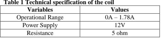
Since the project is based on magnetic repulsion, there are some important adoptions that need to be taken for the plant construction. The structure depicted on figure 1, includes a sensor located at the top of the station (SHARP GP2D12 F 5X), and a coil located at the bottom of the system. The specs of each coil must be selected according with the different needs and requirements for the platform, for this special study case specs are described on table 1.
A small magnetic piece is placed under the levitation object, unless the subject had some magnetic properties. The magnet
Maglev Kit: A Servo/Regulatory Configuration
For Low-Cost Educational Laboratories
Figure 1 Prototype hardware configuration
[image:2.595.51.289.55.220.2]is needed to contribute stability to the design. Reader must keep in mind that the repulsion forces should be enough to equalize the gravity forces, so magnet specs shall be selected according with the properties of materials for the construction of each station. The usage of a magnet piece brings another restriction, the need of a straight guide to frustrate the magnetic piece attempts to align itself with current magnetic field. See figure 1.
Table 1 Technical specification of the coil
Variables Values
Operational Range 0A – 1.78A
Power Supply 12V
Resistance 5 ohm
III. CONTROL STRATEGY
The identification process reveled, the high lack of linearity on the system, which is useful due the educational goal of this project. For this demonstration the gain scheduling technique is selected [2], which is based on the idea that different plants are taking place along all operational control range, so each plant should have its own PI controller [3].
The gain scheduling requires the linearization of the system, hence lineal control techniques may be applicable for each equilibrium point to support an acceptable close loop response. To mention some of the goodness of this strategy, the mathematical complexity is significantly reduced which impacts directly to the computational requirements, adding the feasibility of building an integrated board with all strategy incorporated [4]. The block diagram is illustrated on figure 2.
[image:2.595.41.298.357.418.2]In control theory, gain scheduling is an approach to control non-linear systems, with the usage a family of linear controllers, each of them providing a satisfactory control for each operational point. One or more observable variables, called the scheduling variables, are used to determine what operating region is being requested or operating, therefore the appropriate linear controller is activated [5].
Figure 2 Process block diagram
It is one of the simplest and most intuitive forms of adaptive control, which involves modifying the control law used by a controller to cope with the fact that the parameters of the system being controlled are slowly time-varying or uncertain.
Typical applications of adaptive control are (in general) [6]: Self-tuning of subsequently fixed linear controllers during the implementation phase for one operating point;
Self-tuning of subsequently fixed robust controllers during the implementation phase for whole range of operating points;
Self-tuning of fixed controllers on request if the process behavior changes due to ageing, drift, wear etc.;
Adaptive control of linear controllers for nonlinear or time-varying processes;
Adaptive control or self-tuning control of nonlinear controllers for nonlinear processes; Adaptive control or self-tuning control of multivariable controllers for multivariable processes (MIMO systems);
IV. IDENTIFICATION PROCESS
Table 2 Laplace functions for each plant
V. TUNING METHOD
Previous experience and knowledge of the plant is always essential for an acceptable or good controller parameters selection. It is common a good selection of controller parameters with a good or poor stability within known plants. For this study case several parameters were selected randomly by just intuition, technique that is commonly the first attempt for most of the students, although any of these attempts were close to be a good controller selection, it just confirmed the need of a different control strategy instead of a simple PID. Derivative constant should be avoided, since during exploratory experiments the usage of a derivative constant resulted in a high instability, the only conclusion from this first approach was to define the avoidance of a derivative constant.
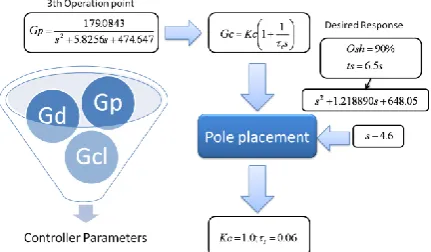
[image:3.595.50.291.517.686.2]With this in mind the tuning process continued with the pole placement technique obtaining different parameters for PI controllers used with the gain scheduling implementation. The Pole placement technique let designer to specify the desired behavior of the system in closed loop configuration, this gives the advantage to be able to obtain tuning parameters independently of the process order [8], [9].
Figure 3 identification process of the 3rd point
Figure 4 Controller tuning with pole placement method
To explain the following method we will use the third operation point to implement pole placement. The model procedure is depicted on figure 4. User must look for PI parameters to force close loop response to perform in a desired way, design parameters such as overshot and stability time must be defined [9].
It is important to consider different factors such as friction and weight. Those variables affect the plant and needs to be taken in account to establish a realistic desired performance. After several experiments to recognize the plant, was concluded that overshot ought to be close to 90% in order to exceed friction effects and gravity force to achieve a good vertical movement. This parameter impacts directly to the controller manipulation to be good enough for the first peak or impulse to reach the desired set point, besides giving a good response against disturbances.
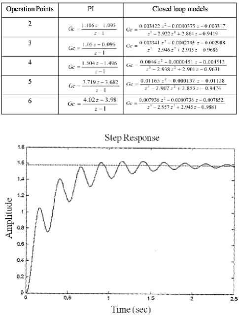
Pole placement was used for each of the operational points giving different tuning parameters illustrated on table 3. Table 3 PI Parameters
Table 4 Discrete transfer functions
Figure 5 Simulated response for the 3rd point
VI. EXPERIMENTS AND RESULTS
To evaluate the performance and reliability of the system, for each operation point was programmed several tests. A routine called “train pulses”, programmatically applied, gave an acceptable number of iterations changing the set point sequentially and repeatedly, in addition a second test consisted in giving a sequential ascending and descending set points, this test was called “stair test”.
During all tests can be noticed an intrinsic noise due the hardware interaction, which may be filtered or improved by students with the usage of digital filters. The lack of clean signal could be taken as improvement areas for further works. From “Stair test” can be demonstrated the no linearity of the levitation system, even when it is controllable, instructor can easily demonstrate the no linearity topic, notice that during ascending pattern response doesn’t have same pattern as descending sequence, which is clearly seen from chart in figure 6. Observing controller manipulation, the no linearity is also exposed, since 1.1v differential is need to enforce a set point change of 1mm, while in other operation point a change of 1.8mm just need a 0.8v differential. On the other hand system behaves slower when descending comparing with the ascending pattern.
[image:4.595.49.292.61.381.2]Figure 6 Performance against continuous references changing at different levels.
[image:4.595.307.550.284.416.2]Figure 7 Reliability performance test
Figure 8 Regulatory performances test against disturbances
From “train pulse test” the subject of control was forced to levitate between two different operation points, as can be seen from figure 7, a very consistent performance was observed, it demonstrates the different performance when ascending vs. descending, but even when no linearity is present a good performance is observed with actual controller implementation.
[image:4.595.308.545.450.618.2]applied and recovery time was about 1.3 seconds. See figure 8.
VII. SOFTWARE DEVELOPMENT
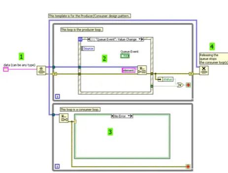
[image:5.595.60.292.308.484.2]The project was implemented on LabView platform using the Producer and Consumer architecture, design pattern based on the Master/Slave pattern, geared towards to enhance data sharing between multiple loops running at different rates. As with the standard Master/Slave design pattern, the Producer/Consumer pattern is used to decouple processes that produce and consume data at different rates. The Producer/Consumer pattern’s parallel loops are broken down into two categories; those that produce data and those that consume the data produced. The software architecture is a standardized technique for programming, which gives several benefits in terms of timing manipulation. Maglev system is a very tight project in terms of time restrictions; the proposed technique permits the evolution to different controllers which may demand a higher sampling rates[13]. Communication between producer and consumer loops is done by using data queues see Figure 9.
Figure 9 LabView Template for Producer/Consumer Architecture
Figure 9 illustrate a generic template provided by LabView patterns, which in sections 1 and 4 depicts the queue task procedure, which are triggered by section 2 and performed by section 3. Always sensor feedback system through section 2 will generate events that will trigger activity for PID located in section 3, giving a good time response and significant reduction of memory usage for the computer.
VIII. CONCLUSION
Due the nature of this schema which involves magnetic levitation, results to be an attractive study case to encourage students into the controls and automation sciences. On the other hand we can find several topics illustrated in a real world environment, to demonstrate i.e. no linearity, PID effects, different and more complex control strategies, and electronics with signal filtering or whole hardware construction, as well as DAQ systems, sampling interval importance.
ACKNOWLEDGMENT
First and foremost, author would like to thank to Rheem Manufacturing Company, Research and Development center under direction of Mr. Arturo Caballero Zepeda and Mr. Brad Campbell, for their valuable guidance and advice, providing the financial support and effective environment to encourage the research and development spirit of their work team.
REFERENCES
[1] D. Ibrahim, “Teaching digital control using a low-cost
microcontroller-based temperature control kit”, Int Journal of electrical engineering Education” pags 40-43, 2003.
[2] Leith D. J., “Survey of Gain-Scheduling Analysis & Design,” , International Journal of Control. 1999.
[3] Hizal, Nafiz Aydin, “Gain Scheduling Adaptive Model Control”. Tubitak Journal, 1999.
[4] Lawrence, Douglas and Rugh, Wilson J. , “Gain Scheduling Dynamic Linear Controllers for a Non-linear plant,”IEEE pags 1024-1029. [5] Ogata, Katsuhiko, “Modern Control Engineering”, 4th Edition, pag
685., 2003.
[6] K. J. Astrom and B. Wittenmark, Adaptive Control, Addison-Wesley, 1989, 2d ed. 1994.
[7] Sinha, Rishabh y Nagurka, Mark. “Analog and Labview based Control of Maglev System with NI-Elvis” IMECE2005-81600, 2005. [8] Belur, Madhu, Trentelman H.L., “Stabilization Pole Placemente and
regular implementability,” IEEE 1993 Transactions on Automatic Control Vol 47, No 5. 2002.
[9] Brasch Jr. Frederick and Pearson, James, “Pole Placement using Dynamic Compensators” IEEE Transactions on Automatic Control. pags 35-43, 1970.
[10] Rashid, Muhammad, “Electronica de potencia: circuitos, Dispositivos y Aplicaciones” Pearson Education. 1st edition, 1995.
[11] Kuo, Benjamin C. “Digital Control Systems”, CECSA, 2nd edition, 2003.
[12] Ogata, Katsuhiko, “Control Systems in discrete time”, Pearson 2nd Edition, 1993.