Geographic Routing in Wireless
Sensor Networks for Surveillance
Introducing a novel routing algorithm: GZOR
Date last modification 24/06/08
Author Arjan Dam
arjandam@gmail.com
Supervision Ir. J. Scholten
Ing. P. J. M. Olde Damink M.Sc. J. Slagman
Dr. Ing. P. Havinga
Surveillance
Master of Science final project: “Introducing a novel routing algorithm: GZOR”
Student Arjan Dam 0020818
arjandam@gmail.com
Supervisors:
J. Scholten, University of Twente
P.J.M. Olde Damink, Thales Nederland B.V. J. Slagman, Thales Nederland B.V.
A
BSTRACTWireless Sensor Network (WSN) technology is an upcoming field of research throughout the last decade. Thales Nederland B.V. is investigating if this technology is applicable for surveillance purposes, in cooperation with Twente University. In this scenario such a network will have to exist of thousands of positionaware sensor nodes. The nodes must monitor a large area to detect and report incidental hostile intrusions. Intrusion data has to be transmitted to a base station. Therefore the network will be equipped with dozens of gateway nodes, which have a stronger radio and battery and are able to communicate with a base station. The sensor nodes must route the detection data to a gateway by means of a multi hop routing algorithm.
Since the nodes need to be position aware for the surveillance purpose, this information can be util ized to increase efficiency and performance of routing algorithms. Geographic routing algorithms form a subclass of WSN routing algorithms. They are developed to deliver reliable anytoany connections between all nodes in an energy efficient and scalable manner. The intended surveil lance network does not share these hard requirements. This research has explored the possibilities to improve the energy efficiency by loosening the delivery requirements. This has led to the develop ment of a novel geographic routing algorithm which is introduced in this document. Geographic Zero Overhead Routing (GZOR) is a statefree algorithm based on the concepts of volunteer forwarding and multipath routing. This combination creates robust and dynamic routing paths. The algorithm is intended to route packets from nodes to gateways with an acceptable delivery rate. This can be summarized as besteffort manytosome routing. GZOR nodes do not explore the network topology and do not provide transmission feedback. As a result, GZOR does not require proactive or reactive communication overhead. This property causes GZOR to be very energy efficient and scal able. It also allows nodes to engage in asynchronous energyconserving sleep cycles, which can greatly extend the lifetime of a network.
S
AMENVATTINGDraadloze sensornetwerktechnologie is een opkomend onderzoeksveld sinds de laatste tien jaar. Thales Nederland B.V. onderzoekt in samenwerking met de Universiteit Twente of deze technologie toepasbaar is voor bewakingsdoeleinden. In dit scenario zou zo'n netwerk moeten bestaan uit duizenden positiebewuste sensor nodes. De nodes moeten een groot gebied monitoren en zodoende vijandige indringers detecteren. De detectieinformatie moeten worden doorgezonden naar een basis station. Hiervoor moet het netwerk worden uitgerust met zogenaamde toegangsnodes. Deze nodes hebben een sterkere radio en batterij, waardoor ze in staat zijn tot communicatie met het basisstation. De sensor nodes moeten elkaars detectie data routeren naar een toegangsnode door middel van een multihop algoritme.
De nodes moeten hun positie kennen voor het bewakingsdoeleinde van het netwerk. Deze infor matie kan ook gebruikt worden om de energie efficiëntie en schaalbaarheid van routing algoritmes te verbeteren. Geografische routeringsalgoritmes maken hiervan gebruik en vormen een subklasse van routeringsalgoritmes. Deze algoritmes zijn ontworpen om betrouwbare éénopéén verbin dingen tussen alle individuele nodes in het netwerk tot stand te brengen op een efficiënte en schaal bare manier. Voor het beoogde bewakingsdoeleinde hoeven nodes alleen naar toegangsnodes te routeren en een acceptabele hoeveelheid aan dataverlies is toegestaan. Daarom is er onderzocht of het versoepelen van de netwerkeisen kan leiden tot een algoritme dat nog zuiniger omgaat met energie. Dit heeft geleid tot de ontwikkeling van een nieuw algoritme, dat in dit document geïntro duceerd wordt. Geographic Zero Overhead Routing (GZOR) is een toestandsloos algoritme, geba seerd op de concepten van vrijwillig doorsturen en routering over meerdere paden. Deze combinatie stelt GZOR in staat om robuuste en dynamische routeringspaden te creëren. Het algoritme is bedoeld om pakketten te routeren van nodes naar toegangsnodes met een acceptabele aankomstratio. Dit kan worden samengevat als bestepoging, veelnaarenkelen routering. GZOR nodes hebben geen informatie over de netwerktopologie nodig en geven ook geen terugkoppeling over het succes van transmissies. Daarom heeft GZOR geen proactieve of reactieve communicatie overhead nodig. Deze eigenschap zorgt ervoor dat GZOR heel erg energieefficiënt en schaalbaar is. Het algoritme staat ook toe dat nodes zich in asynchrone energieconserverende slaapcycli begeven. Dit kan de levensduur van een netwerk aanzienlijk verlengen.
8.2 Behavioural analysis...45
8.2.1 Multipath emergence...45
8.2.2 Link filtration...46
8.2.3 Network connectivity void handling...47
8.2.4 Dynamic routing paths...50
8.2.5 Simultaneous crossing data streams...52
8.2.6 Lifetime estimation...53
9 Discussion...56
9.1 Delivery rate...56
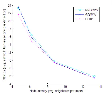
9.2 Stretch...56
9.3 Energy efficiency...57
9.4 Overhead...57
9.5 Scalability...57
9.6 Localization...57
10 Conclusion and Recommendations...58
11 Acknowledgements...60
12 References...61
Appendix A: Simulation details...65
Appendix B: Node deployment...68
G
LOSSARYACK Acknowledgement. Feedback of a receiving node to the sender whether the transmission was successful.
Ad hoc functionality The functionality of nodes to form a functional network autonomously, without central control.
Anchor GPS-equipped node.
Asynchronous sleep cycle The sleep cycle is the proportion of time a node is not operational. Asyn-chronous sleep cycles are uncoordinated sleep cycles. Nodes do not know when their neighbours are asleep.
Connectivity void A physical area in the network without links between the nodes on either side of this area.
Delivery rate Percentage of transmitted packets received by a gateway.
Dijkstra's algorithm Graph search algorithm which can find the shortest path between two vertices.
Duty cycle Proportion of time during which a node is in reception mode.
ETX Expected transmission count. The average amount of packets that must be transmitted to get a packet over a link with a certain PRR.
Face routing Routing algorithm which uses the planar graph to route around connectivity voids.
Gateway A node capable of communication with the base station.
Greedy routing Routing algorithm where a node forwards packets to the neighbour which would induce the most progress towards the packet's destination. GPSR Greedy Perimeter Stateless Routing. A WSN routing algorithm which
combines greedy and face routing.
GZOR Geographic Zero Overhead Routing. The novel algorithm described in this document.
Isotropic Uniform behaviour in all directions.
Localization The process where nodes acquire their position through communication with surrounding nodes and anchors.
MADM Multiple Air Deployment Model. A network model which consists of several overlapping aerial deployments.
Mica2 node Sensor node developed by crossbow, equipped with a CC1000 radio module.
Overhead Transmitted data required for routing purposes. All data that is not detection data is overhead. In this document the term overhead points at packets without detection data.
Planarization A process where all crossing links of a network graph are removed from routing tables.
PRR Packet Reception Ratio. The probability on successful reception of a packet across a link between two nodes.
RSS Received Signal Strength. The intensity (dB) of the received signal in relative to some reference. This value is commonly used as an indication on distance between two nodes.
Stretch The average summed amount of transmissions the nodes in a network must to do to get a single packet from sender to destination.
Thales simulator The Matlab WSN simulator developed as a student research project within Thales.
TinyOS The operating system running on the Mica2 sensor nodes.
1
I
NTRODUCTIONContext of this document
This document contains the fourth student research on wireless ad hoc sensor networks performed in a cooperation of Twente University and Thales Nederland B.V. Thales is interested in this field of research since this technology has potential to offer an efficient mechanism to extend the ground surveillance possibilities. A wireless sensor network (WSN) consists of a large amount of small, lowcost, radio equipped, batterypowered sensors, which are called nodes. These nodes, once deployed, have to localize themselves and form a network autonomously. An intruder, entering the network deployment area, will be detected by the nodes. After a detection, the nodes try to report this information to the military base, where the detection data can be postprocessed. Such a network has to be operational for at least several months after deployment, therefore energy efficiency is a major factor in the design of this technology.
Currently, Thales is specialized in radar technology and offers a ground radar solution for compound security and area surveillance. This technology, however, does have some vulnerabilities. A radar installation is a very expensive piece of equipment and has to be manned and guarded continuously, which could impose high risks in a hostile environment. Besides, as radar is a central ized solution, it is susceptible to objects blocking its line of sight. Wireless sensor network techno logy might offer a good solution for monitoring enemy activity in blind areas of the compound radar or in hostile territory where deployment of a radar installation is difficult, dangerous or completely impossible. Wireless ad hoc network technology is currently still in its infancy. Thales would like to explore the possibilities of this new technology and gain knowledge about the viability of this solution to meet military surveillance requirements. Prior to this research, the global concepts of WSN technology were explored and an assessment was made about applicability for surveillance purposes [Bos06]. This survey was followed by a research that focused on node localization algorithms based on signal strength indications (rangefree localization) and the presumption that a subset of nodes is equipped with a GPS module (anchors) [Sla07]. The third research focused on simulation of high level WSN algorithms for operation in large networks [Dam08].
Problem statement
A wireless sensor network consists of a large amount of sensor nodes with a lowpower radio. When a node detects an intruder, it must report this to the base station. The radio of a node itself, unfortu nately, is not strong enough to send its detection packet directly to the base. It can, however, reach its neighbouring nodes. Therefore the network has to be equipped with gateway nodes, also known as sinks, which have a stronger radio and can directly transmit to the base. The network nodes can now cooperate, forwarding the detection message until it reaches a gateway, where it will be trans mitted to the base. This method is called multihop routing. Since all nodes are battery powered, this forwarding has to be done according to an efficient algorithm, where as much energy has to be saved as possible. Since the nodes are aware of their position, or at least have an estimation of it, this information can be used to aid routing. This class of routing is calling geographic routing. This research aims at the development of such an algorithm. This algorithm has to be robust, reli able, efficient and scalable. The algorithm has to be simulated in order to monitor its behaviour and assess whether it holds the above mentioned properties.About this document
2
R
ELATED WORKMultihop routing algorithms have been a major issue in the WSN research field for many years. Traditional solutions to this problem are dynamic source routing (DSR) [Jon96] and adhoc on demand distance vector routing (AODV) [Per99]. DSR tries to discover routes from sender to destina tion with network floods. Intermediate nodes forward route discovery packets and append them selves to it. When the destination receives such a packet, it knows the route from sender to destina tion, and replies to sender along this route with this information. In AODV, nodes will construct a local routing table on demand. This table contains information through which neighbour a gateway node can be reached and at what cost. Nodes broadcast this information to each other, so every node knows at a local level to which node specific packets have to be forwarded. Both algorithms require a relatively high amount of overhead to share topology information resulting in scalability and energy performance issues.
For surveillance purposes nodes are required to know their position, or at least have a good estima tion. Otherwise the detection information they broadcast would be useless, since the location of a detection is essential. Position information can be utilized to aid routing and reduce topology information overhead. This subclass of multihop routing is calling geographic or locationbased routing. Since this method offers great potential to reduce overhead and thus save energy, a great amount of research has been done to create a solution to exploit this information as much as possible [Gio04].
Karp proposes a solution called geographic forwarding [Kar00]. This method uses greedy forwarding to decide to which node a packet must be forwarded. Every node knowns the location of all of its neighbours and packets contain the location of the destination. Nodes forward packets to the neighbour closest to the destination, which ensures that every broadcast will result in the packet travelling towards its destination. Since topology information only has to be exchanged locally, greedy forwarding is very scalable and many variants have been proposed [Bar01], [ZSK06]. The largest problem with this method is overcoming holes in network connectivity, nodes that do not have a neighbour closer to the destination than itself. Most algorithms use a variant of greedy peri meter stateless routing (GPSR) [KaK00] to bypass such a void (FACE [Bos01], GOAFR+ [Kuh03]). Ko and Vaidya suggest an approach where DSR is optimized by restricting a route detection network flood to the direction of the destination [KoV00]. This method is known as locationaided routing (LAR) and prevents networkwide floods [Mar04]. Variations to this technique also explore possibil ities to use multipath routing for increasing robustness and reliability [Gan01], [Dul03].
3
R
EQUIREMENTS ANALYSISThe goal of this research is the design of a routing solution for a surveillance network proposed by Thales. For this purpose the boundary conditions and network requirements first have to be identi fied. This chapter states the global requirements and gives insight into smaller design issues.
3.1
Energy efficiency
Once the network is deployed, it has to be operational for at least several months. This requirement introduces the need for energy efficiency. Therefore it is important to identify the different states of a node and the power consumption concerned with such a state. • When a node does not participate in the communication process at all, is it said to be in sleep mode (radio off). The sensor of the node is functional, but the node will not hear other nodes broadcasting. This state has the lowest current draw (<100µA) [Shn04]. • If the node is able to receive packets from neighbouring nodes and thus is listening to the radio channel, it is said to be in idle mode (radio on). A node in idle mode consumes 100150 times more power than in sleep mode (current draw: 10mA) [Lan05]. In idle mode the node can use a duty cycle mechanism [YeS06], which means the node's radio is rapidly alternating between listening and sleeping (for instance 1% listening, 99% sleeping). When another node wants to send a packet, it first sends a preamble, which takes long enough so that all the nodes will have some duty time to hear that a packet will be sent shortly. With a 1% duty cycle the current draw is 0.1mA [Chi06]. • When the node is receiving a packet, it consumes 20% more power than in idle mode. The current draw is 12.5mA [Shn04]. • If the node is transmitting a packet, it draws twice as much current as in receiving mode (25mA) [Shn04]. • Communication is in terms of energy consumption the most dominant factor, internal calcu lations are only invoked by sensor readings or received transmissions. While executing instructions, the node draws 8mA [Shn04]. When analysing the above, transmission is clearly the most costly state, also since it causes the reception state in all receiving nodes [Fee01]. However, it can also be concluded that the difference between the transmission state and the idle state (incorporating a duty cycle mechanism) is of the same significance level as the difference between idle and sleep state. Energy conservation in terms of routing therefore not only lies in the reduction of transmissions, but also in the ability of a routing algorithm to cope with some amount of nodes in longer sleep states. This is especially important because the network will have no transmissions at all during most of its lifetime (since the presence of intruders is considered a rare event).
3.2
Ad hoc functionality
Since the network must be capable of being deployed by an aerial vehicle in a hostile environment, the nodes must be able to autonomously form a network environment capable of localization and routing, and maintain this property. The network will consist of a certain amount of anchor and gateway nodes. The nodes must for themselves decide to which gateway their packets should be sent and how to do this. Nodes are considered to have a stable position. The network should also be able to be extended with another air drop. The new nodes must be able to easily integrate with the operational network, forming a new larger (or denser) network. When a node stops functioning, it should be able to easily leave the network, without causing network routing to fail.
3.3
Robustness and reliability
• Radio nodes do not have isotropic transmission ranges, links can be asymmetric and unstable [Zho06].
• The transmission ranges of nodes are not stable, they change due to weather conditions and battery charge depletion [Sla07].
• Due to energy conserving sleep modes, nodes might temporarily be unavailable. • Concurrent packet transmission can cause packets to get lost [Son06].
• The network will not be uniformly distributed and can contain network connectivity voids.
From these network properties it can be concluded that the topology of the network is continuously changing. A routing algorithm should be robust enough to handle the changing topology and offer the availability of nodegateway connections without an extreme amount of topology overhead. When detection occurs, the nodes will start to send data at a rate of at most 1 Hz. Postprocessing requires that at least 90% of the data arrives at the base and that data must arrive with a maximum delay of 5 seconds [Bos06]. The reliability can be defined as the minimum delivery rate, which must be at least 90%. Reliability can be improved by retransmissions in case of packet loss and multiple routing paths for the same packet (these methods add redundancy in time and space respectively). Note that the surveillance purpose of the network loosens the requirement of ensuring packet delivery guarantees. As long as the delivery rate is high enough, a besteffort network is a viable solution.
3.4
Scalability
The intended network must be able to monitor an area of about 10 hectare. With a common per node detection range of 10 meters maximum, this causes an extent of the network to at least 1000 nodes. Larger monitoring areas or nonheterogeneous node distribution increments the required number of nodes rapidly.
This implies that it is impossible to have full network topology information for every node. Routing algorithms on networks at this scale must ensure to have at maximum a linear increase of topology overhead. Maintaining routing tables or nodetogatewayroutes induces too much overhead, espe cially when the network topology is rapidly changing (section 3.3). Optimal paths conserve energy, but the tradeoff against network overhead to find and maintain such paths might lead to the situ ation where the use of nonoptimal paths is a better strategy.
4
R
ESEARCHM
ETHODOLOGYThe usage of wireless sensor network technology for security purposes is a new concept of which there currently does not exist a functional implementation. The requirements stated in the previous chapter differ from what is considered standard in terms of scalability and durability in the field of WSN research. Most research focuses on manytomany reliable communication between nodes in a 100 node network. Our intended solution, however, involves manytosome reliableenough commu nication in a 1000+ node network. Although the basic hardware technology is the same, the differ ence in application requires to reexamine current routing algorithms and their applicability in our intended solution. Within this research the latter has led to the design of a new routing algorithm specifically designed for the surveillance purpose solution of Thales. The algorithm is called Geographic Zero Overhead Routing and will be referred to as GZOR throughout the rest of this document. Although the developed algorithm could be applicable to other applications in the WSN field, this has not been the focus of this research.
4.1
Simulation
The process from design to final implementation of a routing algorithm goes through several stages, including theoretical design, simulation, prototyping, implementation and testing. This research only involves the first two steps and aims at the demonstration of the theoretical viability of the created solution. The latter justifies taking the future next step of creating a prototype, which in this field can be very costly. The research scope is illustrated in Figure 1.
[image:17.595.166.473.377.561.2]In order to demonstrate the viability of the designed algorithm it is very important to have a realistic simulator. The simulator must not only be founded by stateoftheart knowledge on radio beha viour, it must also be able to give insight in the properties of the developed conceptual algorithm. The previous research performed within Thales by the author of this document has focused on the development of such a simulator [Dam08]. This simulator is based on a radio model of the Mica2 node, the development platform adopted by Thales for research on WSN technologies. Another Mica2 simulator is Tossim [Lev03] (included in the standard TinyOS release), which can execute and simulate NesC code written for the TinyOS [Lev05] platform. This simulator can be well used to evaluate, test and debug algorithms during future implementation stages. However, Tossim requires a full NesC implementation of algorithms, which could distort the focus of design at the current stage of development. This prevents from quickly exploring new fundamental concepts of geographic routing. Furthermore, this simulator does not allow reproducible experiments and inter action with the simulation is considered laborious by the Tossim developers. Therefore the Thales simulator is a better platform for design and analysis of routing algorithm concepts.
The simulator described in [Dam08] only supports methods for quantification of algorithms. There fore the simulator had to be extended for support of analysis of algorithm behaviour. This includes reproducible experiments where the path of a packet traversing through the network can be evalu ated, as well as the routing decisions made on each specific node along the way. Details on the extensions can be found in section 7.3.
4.2
Evaluation and quantification
The research goal is the development of a routing algorithm specifically suited to deal with the requirements imposed by the hostile security environment. It is important to evaluate this algorithm by means of a simulation, which closely resembles the conditions an actual implementation will have to cope with in practice. This means that in order to evaluate the performance of GZOR, the simulation must include nontrivial imperfections, such as localization errors and nonoptimal node deployment. In chapter 7 details on the simulation conditions are elaborated.
For performance measurement of GZOR it is important define calibration points for evaluation. In addition, metrics need to be defined for comparison with the calibration points. The approach of this research includes two calibration points: a lower bound and a competing algorithm. The lower bound is a mathematical analysis of the network and a calculation of the optimal path. An average better performance than the lower bound is theoretically impossible. The competing algorithm is the geographic WSN routing algorithm Greedy Perimeter Stateless Routing, which is developed and thoroughly examined by other research groups [Sea07] [Kim05] [Fre06]. This algorithm and the implementation used for comparison is described in chapter 6.
The metrics used for quantification, evaluation and comparison of GZOR's performance are defined as follows:
• Delivery rate (%): The percentage of packets that successfully arrive at the intended destination. • Stretch (#transmissions): The average sum of transmissions that the nodes in the network must
do to get a single packet from a source node to destination.
• Node density (neighbours/nodes): The average amount of neighbour nodes a single node has in the network. Two nodes are defined to be neighbours if they can communicate with each other with a packet loss probability of less than 30% (bidirectional).
• Percentage of asynchronous sleep (%): The percentage of time operational (nongateway) nodes asynchronously switch off their radio to engage an energysaving modus.
Both algorithms are quantified according to these metrics. The comparison of GZOR with the two calibration points gives a solid view on GZOR's performance. This provides a foundation on which the conclusion on the viability of the new routing concept for the intended solution is based.
5
D
EVELOPMENT OFG
EOGRAPHICR
OUTINGA
LGORITHMGZOR
This chapter describes the design issues and functioning of the developed geographic routing algorithm. The results of simulations of this algorithm can be found in chapter 8.
5.1
Design issues
Chapter 3 states several requirements that a routing algorithm for this specific purpose must meet. This section tries to describe how these issues lead to design decisions and what solutions are adopted.
5.1.1 Best effort delivery versus reliable data transport
A fundamental issue in the algorithm design process is the decision whether a best effort delivery or reliable data transport strategy is adopted [Wil05]. In a best effort delivery strategy (also known as stochastic delivery) packets are simply sent and no feedback is given back to the sender on the delivery status of the packet. The network tries to deliver the packet, but if it gets lost along the way, no retransmissions will take place. Reliable data transport, on the other hand, offers guaran teed delivery. This can be implemented in two ways. Either the sender gets feedback on the delivery status of the packet in the form of an acknowledgement packet (ACK) from the destination, so that it can consider to retransmit the packet when this ACK stays out (this is called endtoend reliability), or via a perhop strategy, where intermediate hops send feedback messages to each other after each single transmission, so the network itself guarantees delivery at the MAClayer. In both cases, a reliable connection strategy will at least double the number of transmissions needed to get a single packet from sender to gateway. The extra overhead could result in a packet loss increase caused by an increased chance of concurrent transmissions, which leads to even more retransmis sions. This vicious circle occurs when the bandwidth in the network is limited; the effect is amplified when connections are highly unreliable. Retransmissions become the dominant factor, causing the throughput decreasing to a level where the endtoend delay requirement cannot be met. Asym metric links also induce a problem in a reliable data transport strategy, an ACK of a successfully received packet might become lost, resulting in retransmissions and an unnecessary waste of band width. How important is a single detection packet in a surveillance network? We assume that, when an intruder enters the network, the detecting nodes will start to send data at 1 Hz. This means that when a packet is lost, a new packet with roughly the same information will arrive within a second. Since an individual packet does not contain unique, indispensable information, guaranteed delivery is not required. So for surveillance purposes the overall solution can handle a certain amount of packet loss as long as the average delivery rate is high enough. The risk of using a best effort strategy is, however, that individual nodes, whose only path to the gateway is unreliable, will not reach a high enough delivery rate. This could potentially be solved by extra transmissions (what basically happens in a reliable transport strategy), but since the sender does not get feedback this will never happen. Summarized, a best effort strategy offers a higher energy efficiency and throughput and can be used when guaranteed delivery of single packets is not a requirement; it is also less complex from an implementation perspective. Individual nodes, however, are more likely to fail in reaching a required delivery rate when their shortest connection to the gateway is unreliable. This means that the network would require more nodes to reach a certain detection coverage. The marginal costs of individual nodes is assumed less important than the benefits of extending the network's lifetime. Besides that, guaranteed delivery of individual packets is not a hard requirement in a surveillance network. Therefore we adopt a best effort delivery strategy in our approach.
5.1.2 State-based versus stateless
can be done ondemand, which causes delay on packet transmissions, but does not waste energy on maintaining unused links. Maintaining state potentially offers fast, optimal paths. However, in a highly unreliable network where the network topology continuously changes, the amount of over head required to keep the network connected might be insuperable. The second category involves stateless algorithms, in which the sender does not specify a receiver and simply broadcasts the packet on the network (e.g. GeRaF). The receivers decide which node forwards the packet by means of volunteer forwarding, using some mechanism where the node belonging to the most optimal path should be favoured. This method will severely reduce overhead and thus result in a higher energy efficiency. Stateless routing also allows nodes to be in asyn chronous, periodic energy conserving sleep states, which is impossible in statebased algorithms because links would become disconnected. It does, however, induce new challenges such as the risk of packet duplication and the inability to overcome connectivity voids (because opposite to state based routing, nodes are unaware of connectivity voids). Another risk lies in possible concurrent transmissions emerging when two nodes both want to volunteer as the forwarding node. The proposed network has a very dynamic network topology, caused by sleeping states and unreli able links. Also overhead reduction, as a result of the absence of topology information packets, will increase the scalability and lifetime of the network. Therefore the stateless routing paradigm is chosen as a basis for our algorithm.
5.1.3 Multiple short hops versus long hops
The transmission range of a radio node depends on the transmit power. Besides, the further away two nodes are from each other, the more likely the link between them is unstable or asymmetric [Zha03]. This raises the question whether routing over many shortdistance hops is preferred over messages travelling long distances. This way the transmit power could be lowered and also the added interference of a single transmission to the network would be smaller. Or, instead of lowering the transmit power, unstable links could simply be rejected. The complete connection from sender to destination would be more reliable since far and unstable links, were packet loss is more likely, are not used.
In [Hae04], Haenggi argues that transmit power reduction does not lead to reduced energy consumption because of the nature of lowpower radios (power usage of local oscillators and bias circuitry dominate). It is also unclear whether a signal transmission at high power causes more interference in the network than multiple low power transmissions. On top of that, lowering the transmit power of network nodes will cause more connectivity voids in the network and will result in a larger burden to the nodes closest to a gateway. Transmit power reduction is clearly not an attractive option in our case. The rejection of unstable links is another point that needs consideration. Packets can be lost on such a link. In case of reliable data transport or statebased routing link rejection could be an interesting strategy, because it reduces the overhead caused by lost packets or links becoming unconnected. In our case, however, it might be a better strategy to exploit such unstable (or asymmetric) links whenever possible since this reduces the amount of transmissions needed to get a packet from sender to gateway and it increases the chance of leaping over a connectivity void.
5.1.4 Packet duplication constraint
This is illustrated in Figure 2; red lines represent successful transmissions, the numbers indicate the order of events. In the first scenario, node a transmits a packet, node b and c receive the transmission. Node c, which lies closest to the destination, forwards this packet. Node b fails to receive this transmission and also forwards the packet it received from node a. Node d, who has received the transmission from c, will now also receive the transmission from b. Node d already had this packet, so node b did an unneces sary transmission. Note that since node d also receives the same packet from node e, which is closer to the destina tion, it will reject the packet anyway.
Now consider the second scenario, where node d did not receive the transmission from c, but does receive the packet through the transmission from b. Since node d also does not receive the transmission from node e, it will forward this packet and a multipath emerges.
Dropping the constraint of packet duplication could deprive our network of any overhead and exploit unstable connections, at the cost of some unnecessary transmis
sions. Furthermore, possible multipath emergence (which offers more resilience to connectivity voids) will increase the robustness of our routing solution in a tradeoff with increased transmission redundancy. Therefore we drop the constraint of duplicate packet prevention. This method does require packets to have a unique identification number, which must be stored at intermediate nodes, so a single node will not repeatedly forward the same packet. This causes our algorithm to be semistateless; nodes do not keep information about links or neighbours but do (temporarily) store information about received packets.
5.2
Geographic Zero Overhead Routing (GZOR)
The previous section outlines the design issues of the routing algorithm. We call our algorithm Geographic Zero Overhead Routing (GZOR). GZOR has zero topology overhead, but does presume to have a small amount of knowledge of the network (as a result of localization). Since there is no overhead, a node receiving a packet has to solely consider whether to forward or reject the packet. It can, however, hear other nodes broadcasting the same packet and incorporate this information in its decision. This section explains how the nodes make these decisions. Also a mechanism to prevent floods of duplicate packets in the network is presented. We assume that each node participates in the localization process. As a result of this, the node has estimates (by ranging) about the distances between itself and its neighbours. We also assume that a node knows the location of the packet's destination (in this case: a gateway). The global concept of GZOR is a form of volunteer forwarding, where a single node broadcasts a packet without determining the next hop. Ideally, only the furthest receiving node (the one closest to the gateway) forwards this packet. Also, since nodes do not have equal transmission ranges opposite to each other (due to hardware variation, differences in battery power and environmental factors), the node with the furthest reach should be favoured. GZOR tries to approximate this behaviour by using a timing mechanism such that nodes closer to the gateway are more likely to be the first to broadcast. Nodes less close to the gateway will hear this broadcast and decide that their broadcast is unnecessary and therefore back off. When the timer of a node expires without having heard closer nodes broadcasting, it will conclude that there is no node closer to the gateway than itself and forward the packet. This global concept comes with some important issues, we distinguish four: 1. A node must determine whether it should forward or reject a received packet. 2. The node must have some mechanism to assess its distance to the gateway and transmission range relative to other receiving nodes, so it can determine at what value its timer has to be set. 3. When receiving transmissions from other nodes concerning the same packet, a node could use this information to adjust its decision.
4. Nodes may not hear other nodes broadcasting, this causes duplicate packets. Some mech anism has to assure that this phenomenon does not cause network wide floods. For easy comprehension we define the following: • The sender is the node that detects an intruder. This node will create a packet and broadcast it on the network. • The gateway is the destination of a packet. The sender knows the position of this gateway and appends it to the packet. • A receiver is a node who successfully receives a packet and must decide whether to forward or reject it. • An intermediate (relay node) is what a node becomes when it actually forwards a packet. When a sender broadcasts a packet, it is also the intermediate. Receivers refer to the previous sender of the packet as the intermediate, the initial detecting node still remains the sender. So within a packet travelling through the network, the sender and gateway remain unchanged, while the intermediate changes continuously with every transmission.
• distanceToGateway(x) defines the distance of node x the the gateway, which can easily be calculated by using Pythagoras.
5.2.1 Forwarding decision
The solution to the first issue is simple. Since nodes know their location, an intermediate can append its location to the message; receivers can calculate whether they lie closer to the gateway than the intermediate. If they lie closer, they set their timer and place the packet in their broadcast buffer, else they reject the packet. If (distanceToGateway(intermediate) > distanceToGateway(receiver)) forward the packet else reject end
5.2.2 Priority determination
For the second issue, the setting of the timer, GZOR uses two parameters: the distance that the packet has travelled and the estimated transmission strength of the receiver. For the latter parameter GZOR uses the information gathered by the localization process. [Zun04] describes a correlation between the transmission and reception abilities of a single node. In the localization process, the node estimates the distance to all of its neighbours by ranging (measurement of the signal strength); we call the maximum of all ranging values
maxRange. We assume that the value of maxRange will be higher for strong senders. This is caused by the above correlation; strong senders will correctly receive packets from nodes further away and thus estimate their distance. Weak senders will not be able to correctly receive such a packet. We verified this assumption in the simulator; the result is presented in Figure 3. We simulated a localized network with 1216 nodes, distributed according to the groupbased air deployment model (section 5.1.3). For all nodes the value of maxRange was calculated, the nodes were then arranged by transmission power in groups differing 0.25dBm, and the mean of all maxRange values of the group was taken. The result indicates that the maxRange value is indeed a good indicator for the nodes transmission strength. Figure 4 explains the importance of range estimation. The circles in this figure represent the ranges of the blue and red nodes. In this example node 2 has the ability to reach the destination while node 1 does not. However, node 1 lies closer to the destination than node 2. It is favourable that node 2 forwards the packet since this is the only way to reach the destination. However, if node 1 forwards
[image:22.595.348.536.521.688.2]first, then node 2 will cancel its timer and the packet will be lost. When appending the range estimate into the timer equation, node 2 will have a shorter timer than node 1 and therefore it will forward the packet before node 1 gets a chance to do so. As a result, the chance of a packet arriving at the destination increases. Without range estimation, node 1 will forward first since it is the closer node. It should be noted that in an actual implementation also the battery power indicator could be taken into this evaluation. This may be necessary since strong senders may not remain to be so during the lifetime of the network, as a result of being favoured.
The distance travelled by the packet (relative towards the gateway) can easily be calculated, since we know the (estim ated) location of the intermediate (which is appended to the packet) and the receiver. A node can calculate the progress of a packet as follows: packetProgress = distanceToGateway(intermediate) – distanceToGateway(receiver) Note that the packet progress will always be positive since the receiver will only calculate a timer value if it is closer to the gateway than the intermediate, else it would have rejected the packet. The node can now make an estimation about the desirability (and consequently the priority) of itself forwarding the packet and set its timer accordingly. We do this by multiplying the strength indica tion with the packet progress: priority = packetProgress * maxRange The relation between packetProgress and maxRange is 1:1 in this equation, this can be altered in a practical implementation. When we now divide a constant by the node's priority, a value for the timer is acquired which is high for low priority and low for high priority.
timer = constant / priority
Note that the timer values of different receivers are very likely to differ, because they all have different packetProgress and maxRange estimates. A packet's total delay in the network is directly related to the value of the constant. It should be chosen low enough such that the endtoend delay requirement can easily be met, and high enough to prevent concurrent transmissions of duplicate packets.
5.2.3 Network traffic eavesdropping
The third issue concerns a receiver that has correctly received a packet, placed it in its broadcast buffer and is waiting for its timer to expire. In the mean time, the receiver receives the same packet again, but only from a different intermediate. Based on this new packet it can make a judgement about the progress of the packet in the network and possibly alter its own priority (and consequently, its timer) to forward this packet. We distinguish two cases, the intermediate is either closer to or further away from the gateway. In the first case remember the ideal behaviour that GZOR tries to approximate. Apparently, the packet has already travelled past the receiver, so another transmission by this receiver would be unnecessary. The receiver thus responds to this case by removing this packet from its broadcast buffer and stopping its timer (backing off). In the second case, another node has broadcast the packet although it was not the closest receiving node. Since the new intermediate may have reached nodes closer to the gateway which did not receive the packet before, the receiver has to recalculate its timer based on the location of the new intermediate. This prevents nodes, reached by earlier transmissions, to broadcast before closer nodes have the chance, simply because their timer was set earlier. In a network with randomly spread gateways, it is possible that a packet enroute to a certain gateway comes along another gateway. This gateway can of course also accept the packet and send it to the base, in which case no more transmissions in the network are needed. Problem is that in
this case there are still nodes with the packet in their broadcast buffer with sharp timers. This of course also happens when the intended gateway has successfully received a packet and surrounding nodes are uninformed about this event. We circumvent this problem by implementing gateways to broadcast the fact that they received a packet. Neighbour nodes that hear this transmission can consequently remove the packet from their broadcast buffer.
5.2.4 Network flood prevention
The fourth issue is a more theoretical problem. Consider a node with a large distance from its gateway. We would like packets from this node to travel to the gateway in closeto straight path (a near optimal route). Packet forwarding based on distance alone can cause unwanted effects. In theory, a packet can travel completely around the gateway, while still coming closer to it with every single hop. In the worst case almost all nodes around the gateway, closer than the detecting node, could receive this message at some time and forward it
accordingly.
To prevent this kind of behaviour, we add another consid eration constraint for a receiver on which a packet can be rejected. Because the location of the sender and gateway are known to the receiver, the receiver can draw a straight line between these points and calculate its distance relative to this line, which we define the distanceToSenderGate wayPath. This line from sender to gateway resembles the optimal path and forwarding nodes should not differ from
this path by an amount of distance such that a single transmission would not be able to reach nodes close to this path. Therefore, we restrict the receiving node from forwarding if its maxRange value is smaller than the distance from the receiver's location to the sender
gateway path. This is illustrated in Figure 5.
Figure 6 summarizes the decision a receiver will make upon packet reception. Receiver r will only forward a packet intended for gateway D if the original sender lies in the dark grey area and the intermediate lies either in the dark or light grey area. Packets from the white area will always be dropped. If this packet already was in the broadcast buffer, it will be removed and the timer will be cancelled.
Figure 5: A node may only consider forwarding if it lies within maxRange to the sender-gateway path
5.2.5 Pseudo code
The solutions above are now combined with the global concept. The following pseudocode describes the behaviour of a single node when it is triggered by the reception of a packet:
if (rejectionList.contains(packetNumber)) reject;
elseif (broadcastBuffer.contains(packet))
if (distanceToGateway(intermediate) > distanceToGateway(receiver) & intermediate != gateway)
packetProgress = distanceToGateway(intermediate) – distanceToGateway(receiver); priority = packetProgress * maxRange;
timer(packetNumber) = constant / priority; else
broadcastBuffer.remove(packet); rejectionList.add(packetNumber); timer(packetNumber).stop end
else
if (distanceToSenderGatewayPath < maxRange
& distanceToGateway(intermediate) > distanceToGateway(receiver) & intermediate != gateway)
packetProgress = distanceToGateway(intermediate) – distanceToGateway(receiver); priority = packetProgress * maxRange;
timer(packetNumber) = constant / priority; broadcastBuffer.add(packet);
else
rejectionList.add(packetNumber); end
6
I
MPLEMENTATION OFGPSR
The currently most evaluated geographic routing algorithm for WSNs is GPSR (Greedy Perimeter Stateless Routing) [KaK00]. This algorithm theoretically offers delivery guarantees while only main taining and sharing position information locally between nodes in a network (node information does not travel further than a single hop). It was originally designed to function on a unit disk model, which at that time seemed to be an accurate model of a wireless network. Later research, however, showed the opposite. Simulations on arbitrary connected graphs showed that the GPSR algorithm contained possible deadlocks or failed to deliver a packet even when a path from sender to destination was present. Several fixes and variants were proposed to solve these problems. Since this algorithm is widely examined and offers a high delivery rate while maintaining scalability, it seems a logical choice to compare the performance of GZOR with GPSR.6.1
Basics of Greedy Perimeter Stateless Routing
The principle of GPSR is quite simple. Every node knows its own location and also that of its neigh bours, which is stored locally in a table. From a global perspective, the combination of these tables form a connectivity graph. By a beacon mechanism the nodes proactively communicate with each other to keep their tables uptodate. The GPSR solution belongs to a subclass of geographical routing algorithms, all of which combine greedy forwarding and face routing. All algorithms belonging to this subclass consist of a set of individual components, each of which have many vari ants (e.g. the GOAFR+ algorithms family [Kuh03]). The basic idea, however, is always the same. When a node receives a packet, it evaluates the location of the packet's destination and forwards the packet to the neighbour closest to the destination. This process is called greedy forwarding. A problem arises when the forwarding node does not have a neighbour closer to the destination than itself; this situation is called a local maximum. When such a maximum occurs, a backup algorithm (face routing) is initiated to route the packet further and eventually recover from this local maximum. This backup algorithm operates on a planar subgraph of the connectivity graph. The packet traverses along this planar graph until it comes across some node closer to the destination than the local maximum. At such a node, greedy forwarding can proceed. Since the backup algorithm operates on a planar graph, nodes must decide which of the neighbours in their table are part of the planar graph and which are not. This planarization process requires a third algorithm, which must be initiated after each alteration of the neighbour table. The GPSR solution alternates between two routing algorithms, hence it must have information about which one to use. This is stored in the packet itself, which can be in greedy mode and perimeter mode. On encounter of a local maximum, the packet switches from greedy to perimeter mode. On encounter of a node closer to the destination than the location where the peri meter mode was entered (which must be stored in the packet), the packet switches back to greedy mode. An example is given in Figure 7, the destination of the packet is node D. At node a the packet is in greedy mode. It forwards the packet to the neigh bour closest to D, which is node x. Node x does not have a closer neighbour and switches the packet to perimeter mode. The packet is now routed by a backup algorithm via c and d to node e. Since node e is closer to node D than node x, at node e the packet is toggled back to greedy mode, after which it is forwarded to node f and finally reaches its destination.
[image:26.595.392.534.492.655.2]Since GPSR forwards every packet only to a single node, some MAC layer support (acknowledge ments, retransmissions) is required to provide guaranteed packet delivery. In the following sections the different components of the algorithm are folded out. Also the decision is clarified about which variant of each component is chosen for the qualitative comparison with GZOR.
6.2
Neighbour detection and MAC layer support
Unlike GZOR, GPSR contains of several types of packets. These packets can be divided into two categories: proactive topology packets and reactive (detection induced) packets. Although the size of these packets may vary (and consequently, the chance of bit error occurrence), for simplicity they are all treated the same in our simulations. Nodes in GPSR must be aware of the position of their neighbours. In order to maintain their inform ation on their neighbours, they periodically broadcast beacon messages (this is the proactive component). On receiving such a beacon, neighbours reply with their position information. When the beaconing node receives such a reply, it stores the sender and its position in its own neighbour table. The original GPSR algorithm was also designed for mobile (moving) nodes with dynamic positions. In between beacons, nodes could move in and out of range. Therefore upon reception of a data packet of an unknown node, this node is added to the table. When a transmission to a certain node failes, it is removed from the table. Detection of failed transmissions requires MAC layer feed back. During simulation the nodes do not change their tables upon new node detection or transmission failure. Simulations of GPSR done by other research groups [KaK00], [Kim05] all assume bidirectional links and discard links with a Packet Reception Rate less than 70% (nodes with a packet failure probab ility of 30% or more between each other are not considered to be neighbours). We have imple mented this in our simulator as follows. Each node broadcasts ten beacons (serialized), when it receives seven or more replies from an individual node, it adds that node to its neighbour table. Afterwards, all nodes correspond with all of their neighbours to assure that every pair of nodes both agree on whether they are neighbours or not. This avoids asymmetric neighbour pairs. Nodes consider themselves neighbours when at least one of them has received seven beacon replies from the other. Note that this is an optimistic evaluation of link quality, nodes could also drop neighbours if they are unknown to them. Both approaches have been simulated and the latter showed a poorer performance. The communication between nodes for reaching agreement on the neighbour status is considered to be 100% reliable, which in practice can be achieved by MAC layer retransmissions. The reactive component of the algorithm involves nodes sending data packets only to an individual neighbour. Because links with a packet failure rate of up to 30% are used, the algorithm heavily relies on a MAC layer providing reliable transport on such a link. This is implemented in the following manner. When a node receives a data packet, it sends an acknowledgement to the sender. When the sender does not receive this acknowledgement, it will conclude that the transmission has failed and retransmit the packet. The sender will retransmit three times at maximum, after which it drops the packet.6.3
The right-hand rule and face routing
If greedy routing fails, a backup algorithm is activated to route the packet further. This algorithm is called face routing and there are many different variants available. They all have one thing in common, they route along the graph using the righthand rule. This rule is basically a strategy to find the exit of a maze. When the right hand is continuously placed on the wall while walking forward through the maze, the exit will always be reached (in case the maze does not contain loops). In a graph, the righthand rule implies that the next hop is the first node counterclockwise from the previous visited node. This means walking through links as if it were corridors of a maze. When applying this rule in a graph, it will automatically traverse along the interior of a closed polygonal region in clockwise direction, which is illustrated in Figure 8. Such a closed region is called a face. Every graph has several inner faces and one outer face, as can be seen in Figure 8. Alternatively, the
lefthand rule can be applied to traverse along a face in counterclockwise direction. A packet can be
routed across a network along the interiors of a set of adjacent faces, using the righthand rule and changing to new faces according some set of facechange rules. A sequence of visited hops is called a perimeter.
6.4
Planarization of the connectivity graph
When a packet encounters a local maximum, greedy forwarding cannot take it any further. To solve this problem, the network needs to switch to another routing algorithm (perimeter mode) to route the packet around the network void. This can be done by face routing according to the righthand or lefthand rule. Face routing is a wellknown class of graph routing algorithms which guarantees delivery on a planar graph. A graph is planar when it has no crossing edges (links) and all links are symmetric. So in order to apply this algorithm, the connectivity graph as a whole has to be planar. This means that nodes have to decide locally which links belong to the planar graph and which do not. There are several algorithms to do so, the most famous are the Relative Neighbour Graph (RNG) and the Gabriel Graph (GG) algorithms. These algorithms both guarantee to provide a connected planar graph, under the assumption that all nodes have an equal transmission range (unit disk model). In RNG every node considers all of its neighbours and assesses if this neighbour should belong to the planar graph. It does so in the following manner, which is also illustrated in Figure 9. Node u removes the link to node v from the planar graph, if and only if it knows another node w of which the distance to u and to v is smaller than the distance between u and v. Such a node w is called a witness. In GG also every link is evaluated, but in a slightly different manner, which is illustrated in Figure 10. Node u defines a virtual point m at the middle of the link between u and v. Node u removes the link to node v from the planar graph if and only if it knows another node w that is located closer to this point m than u itself. Because the witness area in a RNG is larger, the RNG is a subset of the GG. An example of a graph planarized by RNG and GG is illustrated in Figure 11. As mentioned above, both algorithms rely on the assumption that all nodes have equal transmission ranges, implying that both nodes assessing link uv will see witness w. Empirical results, however, show that this assumption does not hold in practice, as described in chapter 4. When for instance node w does not have an equal transmission range, the situation could occur where node u does see witness w and removes to the link uv from the planar graph, while node v does not. Anisotropic transmission ranges and localization errors can induce crossing edges or asymmetric links in the RNG or GG graph, causing such graphs not to be planar. Routing algorithms relying on the fact that the graph is planar will fail in this case. There is a wellknown fix to this problem, which is the Mutual Witness (MW) extension. In MW, nodes u and v will remove link uv based on witness w if and only if they both see this witness w. This means that nodes u and v have to verify this with each
Figure 9: An edge uv is only included in the RNG if there is no witness w in the grey area [KaK00]
Figure 10: An edge uv is only included in the GG if there is no witness w in the grey area [Kak00]
![Figure 1: Scope of research relative to the complete development process [Ber93].](https://thumb-us.123doks.com/thumbv2/123dok_us/981.647043/17.595.166.473.377.561/figure-scope-research-relative-complete-development-process-ber.webp)