Smart Distribution Coupled Microgrids
Mr. Shubham Purwar1, Mr. Amit Sharma2, Mr. Brijesh Kumar Dubey3
1
Scholar, 2, 3Assistant Professor, Department of Electrical and Electronics Engineering PSIT, Kanpur, Uttar Pradesh
Abstract: Distribution system provides major opportunities for smart grid concepts. One way to deal with the problems of delivery systems is to reconsider our distribution system to include the integration of high level of distributed resources, using micro grid concepts. Improving the basic objectives improves reliability, high penetration of renewable sources, dynamic island, and better generation capacity through the use of waste heat. Managing important levels of distributed energy resources (DER) with a broad and dynamic set of resources and control points can be overwhelming. The best way to manage such a system is to break the distribution system into small clusters or micro ridges, coordinating the distributed optimizing control multi macro grids. Consortium concepts for Electric Reformation Technology Solutions (CERTS) look at the loads associated with cluster generation and grid processing or BMICrgrid. [Cluster sources and loads can be operated in parallel to grid or as an island. This grid can disconnect from the utility during processing events (i.e., defect, voltage collapse), but whenever the quality of the power falls below the grid, it can be intentionally disconnected. This paper focuses on the possibility of smart distribution system using the current state of DER-based distribution, the basics of micro grid, coupled micro grid and autonomic micrograph technology.
Index Terms: Consortium for Electric Reliability Technology Solutions (CERTS); cooling heat and power (CHP); clustered microgrids; distributed generation; intentional islanding; microgrid; smart distribution; uninterruptible power supply (UPS).
I. INTRODUCTION
paper focuses on the possibility of smart distribution system using the current state of DER-based distribution, the basics of microgrid, coupled microgrid and micrograph technology.
II. DER-BASED DISTRIBUTION
The use of DER in distribution system reduces physical and electrical distance between generation and weight. Bring the source closer to the load increase the voltage profile, increase distribution and transmission barriers, reduce loss, increase the use of waste heat, and contribute to deferred investment in the new transmission and large-scale generation systems [3]. Take Portugal as an example; The loss at the transmission level is approximately 1.8 to 2%, while the loss on the distribution grid is about 4%. This is the total loss of approximately 6% except the low-voltage network. Portugal's power consumption in 1999 was about 18 TW. This means that the bigger integration of DER says 20% of the weight, resulting in loss of at least 216 GWH losses. Therefore distributed generation can reduce the loss of 2-4% in the European transmission and distribution network, contributing 20 million tons to Europe contributing per year. A basic issue for DER is technical difficulties related to the control of a large number of distributed energy sources. For example, California could translate the distributed generation objectives to 120 000 one hundred kilowatt generators on their system. If you include renewable goals then the number of DER units is very high. This issue is complicated but the call is one for speedy sensor and comprehensive development in complex control . The fundamental problem with the potentially complex control system for the disaster is that failure of the control component or software error can bring the system down. In the distribution system, DER units should be able to respond to incidents from autonomy using only local information, i.e. voltage, current and frequency. Need to switch to DER Island operations with local loads for voltage droplets, defects, blackouts etc. This will require an immediate change in the output control of the generator because they meet the demands of the transmitted load mode as well as the transmitted power mode to a controlled frequency of the islands of the network. The two main advantages of DER-based distribution have increased capacity by using increased customer reliability through island during the reduction of waste heat and line loss and electricity system outage. The main roadblock is the system's complexities of managing such a wide and dynamic set of resources and control points.
A.Optimal Location for Use of Waste Heat
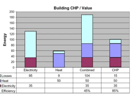
To use a waste heat, the use of waste heat through optimum location coordination or combined cooling heat and power (CCHP) is an integrated energy system, which provides both electricity and useful heat from natural sources such as natural gas. . Most existing power plants provide electricity to user sites at 28 to 32% of the total fuel-to-electricity efficiency of around 70% of the primary energy supplied to the central or distributed, consumer. Figure 1 indicates that the combined efficiency of 45% of a system, which independently produces heat by electricity and natural gas. It is compared to a CHP system for the same electrical and heat load. This CHP system efficiency is 85% [4]. To reduce the loss of energy, it is necessary to increase the efficiency of electricity and / or waste heat from the fuel of the generation plant. The size of the emerging distributed generation technologies can be better placed in the respect of the heat load. Level of production from individual level.The units are small and therefore provide greater flexibility in meeting the requirements of the heat. For example, to match the requirements of the hot water of each floor, fuel cells can be kept on every floor of the hospital and electricity can be provided to the electricity load of the hospital.
B.Power Quality and Reliability
additional generation is available. DER-based distribution can be better organized using many connected building blocks or micro grid. Each microgram has cluster DER units and components with known characteristics are loaded. For example, the larger generation can provide real and reactive power to the power system on a known operating range, while the weight consumes the known real and reactive power. It enables the operation and control of the electricity system. MicroGrid is a new grid resource that provides or absorbs a known range of real and reactive power based on the details of its internal components. Unlike the generation or load, a micrograph can be transmitted uninterrupted between being a standalone island providing energy for a grid resource and local load.
Fig. 1. Combined heat and power.
III. MICROGRIDS
Fig. 2. Grid resource or microgrid.
the components include a wide range of electrical technologies such as IC engine, synchronous generator, gas turbine, microturbine, photovoltaic panel, fuel cells, wind turbine and storage system. Each DER resource has a different reaction time. For example, storage and some fast IC engines can respond in cycles while most of the micro-turbines require seconds to respond to the same load change [9]. These feedback times are important to give a successful response. It is important to keep DER units fast in order to insure the load requirements of the load, firstfewwiks can be supplied during the aftershocks. Pharmaceuticals propodea buffer allows slow response sources to reach their operating points. The controller shown in Figure 2 provides overall system control. This controller interfaces with each DIR unit in microgrid. Its aim is to provide a distributed control system to coordinate the operation of multimricogrid in the distribution system. This communication system is not used for the dynamic operation of microgrid. Faster dynamic requirements are provided through autonomous control over each DER units. This controller not only optimizes the internal operation of the micrograph, it can also respond to system requests for actual and reactive power flows between the microgram and the distribution system. Different micrograph objectives can be achieved based on the mix of DER units and loads. The three main possibilities are high power quality microgridges designed to export high levels of PV energy with the effective use of wastewater, multi-megawatt micrographs and micrographs.
A.High Power Quality Microgrid with CCH
Microgrid components must adhere to peer-to-peer and plug-and-play concepts to insure effective use of high power quality and waste heat. Each source is connected in a peer-to-peer fashion, in which a local control scheme is applicable for each component. This arrangement enhances the reliability of the system against master-slave or centralized control scheme. In case of master-slave controller architecture, failure of the master controller can compromise the operation of the whole system. Plug and Play concepts allow us to expand the microgram to meet site requirements without extensive redistribution. This means that microgrid can continue to operate with the loss of any component or generator. With an additional source, ðNþ1Þ, we can insure full functionality with the loss of any source. The plug-and-play model provides the facility of keeping the generator near the heat load, which allows more effective use of waste heat without the complex heat distribution systems like steam and cooling water pipes. Dispatchable microscuts, such as small variable speed internal combustion engine, require an inverter interface to run a synchronous generator or microturbine. To reduce the effect of source mobility on the microgram operation, sources need a fast response energy storage module, [10]. Storage battery can be
B.Multi-MW Based Microgrid
At the high voltage and power level, microgrid technique scaling transforms the DER mixture. Higher power quality applications are less practical based on peer-to-peer models and inverterbase interfaces. Inverters are prohibited in comparison to other options at several MW level. It is preferred to operate the synchronous generator directly connected to the micrograph [12]. In this case, the governor and the exciter need to modify to comply with the CERTs micrograd criteria. Decrease response time is. Generally the reaction of the synchronous generator is very slow to support the seamless archipelago. Using a directly connected synchronous generation, a micrograph will also need an inverter-based energy source to support the archipelago. There are three source energy sources requiring an inverter interface. They are fuel cells, AC storage and photovoltaic array. Fuel cells are basically defined source systems which require large DC storage to support the island. The photovoltaic array responds rapidly, provided it is solar energy, but is required for micrograph by using directly connected synchronous generator in normal AC storage. The simplest distribution microgrid contains many directly connected synchronous generators and AC storage. AC Storage provides the fast electricity changes required for island and load tracking. Generators provide base load power. In this model DER units still adhere to the plug-and-play and autonomous control model, but the loss of AC storage can prevent uninterrupted islands.
C.PV Microgrid
At present, relatively few entry levels of renewable systems create some problems. As soon as admission gets greater, the availability of the sun becomes a major problem which requires the generation of electricity to the central generation. Such systems are temporary and can be combined with interval loads such as rolling mills and arc furnaces to cause problems of similar stability. Central generation or DER units are required to facilitate power fluctuation from these renewable sources. In any case when there is no sun then the stock is required. A clear solution includes DER units on distribution systems. Without it
Laterer: Smart distribution: Coupled microgridges Volume. 99, Number 6, June 2011. IEEE 1077 proceedings There is a technical limit for storage and / or PV generation on the local generation distribution system. The system of high level of PV entry should be supplemented with resources like storage and local generation to fill local BD spreadable [for temporary loss of solar energy]. PV micrographs can be designed for high export of PV energy without short-term problems related to temporary power fluctuation. DIR units in a PV micrograph can have multi-roles such as control of the actual and reactive power flows between the microgram and the distribution system, when the generation of electricity is not available and the local load is supported during the island, the electricity is filled. Generally, a PV micrograph has photovoltaic energy for export, local generation and / or storage. Generates energy and filling energy required to make the power provided to the generation and size distribution system. Inverter-based AC storage allows the generation to connect directly to the micrograph without the inverter. If the storage is not used then the generation needs a faster response provided through the inverter interface. There are special issues in the island of PV micrograph. For example, PV power level in a PV microgrid can be higher than loading. For this to absorb the extra energy, there is a need for high storage capacity or ways to reduce the generation of solar panels. Power vs. Frequency Drup Controller provides an elegant way to support solar production during low load archipelago. An extra generation island will experience an increase in frequency, which reduces the generation of autonomy from generation to generation, runs storage in a charging mode, and essentially leaves behind PV output easily.
IV. SMART DISTIBUTION
micrograph and the type of DER units is no longer relevant to the transmission of its resources. For example, in a conventional model, a control center transmits the actual and reactive power output of each generator to meet the expected demands of load and can reduce the load in some situations (i.e., Smart Load). Microgrid is a separate grid resource that provides or absorbs a known range of genuine and reactive power based on micrograph details. A micrograph can respond in response to a request for load reduction by closing its internal generation and / or any significant load. It is important to implement smart distribution concepts, there is information on the range of actual and reactive power available for transmission from each micrograph. A PV microgrid can get requests for all the available renewable energy. To portray a multi-MW microgrid potential self-treatment imaginable connected to a 12 KV substation using a quick interface switch. There are several low-voltage high-power quality microgids with this microcridged fast interface switch. This example assumes that only control over each DER unit and interface switches are autonomous algorithms. The simplest MW micrograph can include many synchronous generators and storage. Low voltage, high power quality microgrids will usually be a faster inverter-based source. Each source is connected in a plug-and-pea fashion with a peer-to-peer and autonomous control. The multi-megawatt microgrid island will be with the opening of the voltage collapse interface switch on delivery substation. The storage unit will supply the lost energy within a few milliseconds, the synchronous generators slow down their output. In the end, in the collaboration with the storage generator, it will revise its production autonomously. Island system will be arranged at low frequencies based on electric versus frequency drupt characteristics. Two other interface switches will open either on the original event or this frequency duplex. With rapid changes in the generation of electricity, this fast islanding provides the power of uncontrolled power supply (UPS) quality to low voltage load. If the multi-megawatt microgrid does not have enough generation to support all its loads then the frequency will continue to trigger the load shedding of low priority loads. In the new stable state, there were three related microscopes which supported their related load. When the substation voltage becomes normal, the multi-megawatt microgrid interface switch re-connects with the utility that returns its frequency to the utility. This frequency change will allow two other microgrids to re-connect autonomy distribution microgrid. In essence, this example shows self-treatment and improved reliability features through the use of coupled microgrids.
V. STATUS OF AUTONOMOUS MICROGRIDS
The complexity of the coupled micrographs in the autonomous control concept distribution system implemented on DER units can be very simple. Current testing sites have demonstrated the feasibility of using microgrids as a grid resource. It is meant to configure each DER component with the same autonomous control features that promote this plug-and-play app. These concepts have been applied to two test sites in the hardware. In addition, two field sites are now under construction. The CERTs / AEP microgrid test beds in Ohio are actively testing CERTs concepts in the last five years. Testing involves islanding and reconnecting for many configurations, power quality performance and security strategies. Some important outcomes in Section VI have been discussed in more detail. University of Wisconsin has a micrograd testing facility. It has a low voltage system with a mix of different DER units with a rating of 15 kW or less. This system has successfully displayed an Invertbase microgrid with a smart switch. As part of the UW micrograph, battery storage has been successfully demonstrated in the last two years to include directly connected synchronous generation [13]. A multi-megawatt microgrid is being constructed in Almeida County, CA. This system will integrate AC storage, diesel generator, photovoltaic array, fuel cells, and wind turbine. The original feeder is at 12 KV, which is close to 3 MW of extreme weights. Chevron Energy Solutions is the leading contractor. Sacramento Municipal Utility District, (SMUD) is establishing a high powered quality microgrid with its CHP at its corporate headquarters. SMUD expects to collect electrical quality and CHP data for many years. Base load is 310 kW with a peak of 375 kW. This system will use the three techonic premium power modules rated at 100 kilowatts, along with the CHP and thyristor-based interface switches.
VI. CERTS/AEP MICROGRID TEST-BED:
Fig. 3. CERTS microgrid test-bed (AEP’s walnut site).
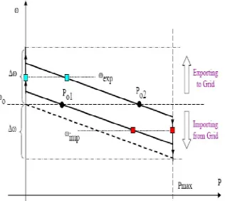
Fig. 4. Steady-state power versus frequency droop.
This process system consists of twelve 7650 ION meters which provide wide voltage and current waves for each stage conductor including neutral. When the microgrid is connected to the utility, its power grows stronger than both the grid and local DER units. If the grid power is lost due to IEEE 1547 events, voltage sags, defects, blackouts etc., then microgrid autonomy will be transferred to the island operation. Figure 4 shows power versus frequency drops for two of the three sources. The slope for AEP is chosen by allowing it to fall to 0.5 Hz because the power extends from zero to maximum output. Figure 4 also shows the Power Set Point Po1 and Po2 for two units. It represents the power transmitted by each unit when connected to the grid. If the system is transferred to the island while importing from the grid, then the generation needs to increase the power generation to replace the lost power from the utility. The new operating point will be at a lower frequency than the nominal value. In this case both sources have increased their power output to their maximum power point with Unit 2. If the system is transferred to the island while exporting the power to the grid then the new frequency will be higher as compared to the low power generation from the sources. These concepts are displayed in the three major tests shown in Fig. 5-7 The first case sees two sources on the same feeder during the island [14]. The effectiveness of sharing this case loading load and the power of maximum limit are displayed. The second test shows smooth reactions to three sources during the island. The final test demonstrates the high level of power quality achieved by using autonomic micrograph concepts. The features shown in Figure 4 are stable-state specifications. They have a certain slope in the area where the unit is operating within its power range. As soon as a limit reaches, the slope becomes vertical. The doop is the location of the stationary-station operating point, but during mobility, the projection will be distracted by these characteristics. Fig. 5. (a) Dynamic response of unit A-1. (b) Dynamic response of unit A-2.
measured on unit A-2. A-2is 55kWandthereactivepower (capacitive) power output of iscloseto5kVAR before the island. Imported grid-related microgrid import implements 32 kilowatts from the utility. After compensation for two units to lose the grid power independently after the island. A-2 overhauled its steady state
Maximum of 200 kilograms for less than 200 million. Control retreats from generation because the unit enhances its output to meet its share of A-1 load. The new stable state operational point for A1 is 29 KW and A2 is 60 KW. Note that the reactive output is greatly reduced. Voltage dimensions are stable through the archipelago phenomenon, which exhibit inertor voltage and stiffness of microgrid stability. Figure 6 shows microgrid islands with three sources working in unit control mode. There are three loads each drawing 37 kilowatt and 20 kVAR. According to the grid load, provides 22 kW with the source providing 89 KW of the required. The top plot in Figure 6 shows the imported power through the steady switch and the power provided by each source. This island event displays the mobility of sources because they lift the lost power from utility. In this figure three other plots are the streams provided by each of the phase-three streams. The voltage on each source is constant and has not been shown. The power sharing displayed in this test is contained in the CERTS concept. The answer to a Power
Fig. 6. Response of three sources to an islanding event.
VII. CONCLUSION
Using a variety of DER units with a sophisticated command and control system, one option of smart grid concepts is to build on micrograd concepts. The use of many microgrids in the delivery system looks simple. Many BSSMAR grids (functions like high reliability, high penetration of renewable sources, self-healing, active load control and better generation capacity through insufficient heat utilization can be implemented using coupled micrographs). Microgride technology is maturing at this point that it is possible to use the PV sources to form a full range of microgram functions with high power quality. To achieve the desired BSMART grid [Objectives], the need to act on the way to transmit many micrographs in the distribution system.
VIII. ACKNOWLDGEMENT
The author gratefully acknowledges the contributions of D. Klapp, S. Casto, H. Volkommer, and R. Hayes of American Electric Power; B. Schenkman and J. Stevens of Sandia National Laboratory; R. Panora and J. Roy of TeCogen, Inc.; J. Wen and P. Piagi of The Switch; E. Linton and H. Hurtado of Northern Power Systems; and C. Marnay and J. Eto of Lawrence Berkeley National Laboratory.
REFERENCES
[1] S. Horowitz, A. Phadke, and B. Renz, BThe future of power transmission,[ IEEE Power Energy, vol. 8, no. 2, pp. 34–40, Mar./Apr. 2010. [2] A. Nourai and D. Kearns, BBatteries included,[ IEEE Power Energy, vol. 8, no. 2, pp. 49–54, Mar./Apr. 2010.
[3] C. Williams, BCHP systems,[ Distrib. Energy, pp. 57–59, Mar./Apr. 2004.
[4] D. Nichols, BBuilding CHP systems,[ in Proc. Distrib. Resources Workshop, Calgrary, May 9–11, 2004, CEA. [5] C. Marnay and O. Bailey, The CERTS Microgrid and the Future of the Microgrid, LBNL-55281, Aug. 2004R
[6] B. Kroposki, R. Lasseter, T. Ise, S. Morozumi, S. Papatlianassiou, and N. Hatziargyriou, BMaking microgrids work,[ IEEE Power Energy Mag., pp. 40–53, May/Jun. 2008.
[7] R. H. Lasseter and P. Piagi, BMicrogrid: A conceptual solution,[ in Proc. PESC’04, Aachen, Germany, Jun. 20–25, 2004.
[8] L. Gyugyi, BDynamic compensation of ac transmission lines by solidstate synchronous voltage sources,[ IEEE Trans. PowerDelivery, vol. 9, no. 2, Apr. 1994. [9] R. A. Panora, J. B. Gehret, Jr., and P. Piagi, BDesign and testing of an inverter-based combined heat and power module for special application in a microgrid,[ in
Proc. IEEE Panel: Microgrid Research and Field Testing IEEE PES General Meeting, Tampa, FL, Jun. 24–28, 2007, 7 pages.
[10] H. Nikkhajoei and R. Lasseter, BDistributed generation interface to the CERTS microgrid,[ IEEE Trans. Power Delivery, vol. 24, no. 3, pp. 1598–1608, Jul. 200. [11] J. Eto, R. Lasseter, B. Schenkman, J. Stevens, H. Volkommer, D. Klapp, E. Linton, H. Hurtado, J. Roy, and N. J. Lewis, CERTS Microgrid Laboratory Test Bed
Report. [Online]. Available: http://certs.lbl.gov/ CERTS_P_DER.html
[12] S. Krishnamurthy, T. Jahns, and R. H. Lasseter, BThe operation of diesel genset in a CERTS microgrid,[ in PES 2008, Chicago [13] R. H. Lasseter and M. Erickson, Microgrid Dynamics With Storage. [Online]. Available: http://certs.lbl.gov/CERTS_P_DER.html