Development of RRR Type Anthropomorphic
Shoulder Joint Model and its Dynamics
Anil Kumar Gillawat1, Hemant J. Nagarsheth2, Mansi Nagarsheth3, H.D. Desai4
Abstract—The authors have developed a shoulder joint model considering RRR type serial manipulator. The servo motors are placed in such a way that they are dynamically balanced. For estimating the torques for each motor L-E method is employed. The joint architecture developed depicts circumduction, pronation and supination and abduction and adduction. Torque values are obtained both analytically and practically. Graphs are plotted and the results obtained are supportive to consider the joint for rehabilitation.
Index Terms—DOF, Revolute, Shoulder, Dynamics, Circumduction, Pronation, Supination, Abduction, Adduction
I. INTRODUCTION
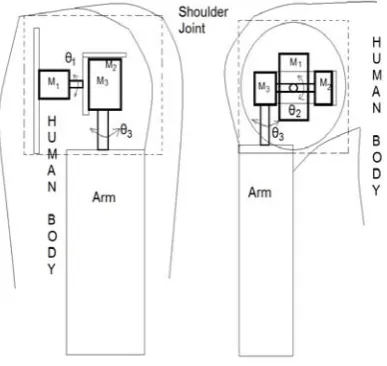
[image:1.595.79.273.410.593.2]This paper presents the work carried out by the authors in developing a model of an anthropomorphic shoulder joint by using three servo motors arranged as RRR-serial jointed arm. The 3 Dimensional, 3 DOF model with base motor as M1 driving a platform accommodating motors M2 and M3 is depicted in Fig. 1.
Fig 1 RRR-Serial Manipulator for Shoulder
Manuscript received 7th March 2012; revised 16th April 2012.
Anil Kumar Gillawat is pursuing his PhD in Mechanical Engineering Department, SVNIT, Surat, India (email: [email protected]).
Dr. Hemant J. Nagarsheth is Dean and Professor in Mechanical Engineering Department, SVNIT, Surat, India (Mb. +919824117447, email: [email protected]).
H. D. Desai is Professor in Mechanical Engineering Department, SVNIT, Surat, India (Mb. +919924900778, email: [email protected]).
Dr. Mansi Nagarsheth, MD (Physiology) is a tutor in Department of Physiology, Govt. Medical College, Surat, India (phone: +912612257571)
The rotation of the motors sequentially represents circumduction, pronation and supination and abduction and adduction of the human arm motion. Considering the above motions the motor positions have been decided and the dynamic equations are formulated and torques are estimated critically using L-E method. The model interface is developed for the shoulder movements and programmed.
Many researchers have carried out work related to kinematics and dynamics of human shoulder mechanism. Few of them are presented here.
patient’s shoulder treatment. S. J. Ball[9] designed and constructed a prototype for upper-limb of exoskeleton robot.
S. Staicu[10] developed dynamic problem for 3-RRR Spherical Parallel Mechanism using the principle of virtual powers. W. Chen et. al.[11] proposed a nine degree-of-freedom exoskeleton rehabilitation based on kinematic analysis of movement of shoulder complex, with six degree-of-freedom shoulder actuation mechanism. S. Sen et. al.[12] proposed a design of a computer model which simulates the movements of the shoulder joint for a specific subject and analysis the three-dimensional forces and torques produced at that joint during movement.
Presently, the authors have designed, developed and tested RRR-serial manipulator for anthropomorphic shoulder joint in a view to minimise the load and torque for the motors. Lagrange-Euler (L-E) approach is used to derive dynamic equations of motions estimating torque.
Steps of Equations of Motion:
1. To identify the generalized coordinates.
2. Computing the Kinetic Energy, KE, as a function of
θ s and θ ′s.
3. Computing the Potential Energy, PE, as a function of θ ′s.
4. Computing Lagrange Function, L KE PE, which is a function of θ ′s and θ ′s.
5. Computing
and
6. Computing generalized force/Torque
τ d
dt ∂L ∂θ
∂L ∂θ
d dt
∂KE ∂θ
∂KE ∂θ
∂PE ∂θ
Since,
0
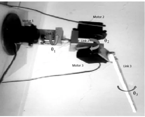
II. TORQUE EQUATIONS FORTHESETUP The torque equations are developed considering mass M attached at the end of link 3 of the model as shown in Fig. 2. The motors can be rotated at angles θ , θ and
θ respectively. The inertias are calculated as a function
f M, θ , θ , θ with fixed link lengths 60 mm, 50mm and 165 mm respectively and mass of each motor as 125 grams.
I 19.607 42.25M 272.25M cos θ sin θ 1.819 sin θ cos θ kgcm
I 4.121 1.82 cos θ
272.25 cos θ 25 M kgcm
[image:2.595.305.549.48.246.2]I 2.426 272.25M kgcm
Fig 2 Constructed RRR- serial manipulator model
Angular velocity and Kinetic Energy due to linear velocity is expressed as
KE 1 2Iω
1 2mV
Hence, KE for each motor is expressed as
KE 1
2I ω 1
2 19.607 42.25M 272.25M cos θ sin θ 1.819 sin θ cos θ ω 10 J
KE 4.121 1.82 cos θ
272.25 cos θ 25 M ω 10 J
KE 2.426 272.25M ω 10 J
Potential Energy is defined as the energy stored due to position and is given by
PE mgr
Hence, PE for each motor is expressed as
PE 216.33 16186.5M 1 cos θ 10
PE 216.33 16186.5M 1 cos θ 10
PE 216.33 16186.5M 1 cos θ 1 cos θ 10
Lagrange Function is defined as
L KE PE
τ d dt
∂L ∂θ
∂L ∂θ
d dt
∂KE ∂θ
∂KE ∂θ
∂PE ∂θ
τ I α I ω mgr
The final equations of torque for each motor are computed and given below
τ 19.607 42.25M 272.25M cos θ sin θ 1.819 sin θ cos θ θ 272.25M
θ sin 2θ sin θ θ sin 2θ cos θ θ 1.819 θ sin 2θ cos θ θ sin 2θ sin θ θ
216.33 16186.5M sin θ 10 N m
τ 4.121 1.82 cos θ 272.25 cos θ 25 M θ 1.82 272.25M sin 2θ θ θ 216.33 16186.5M sin θ
10 N m
τ 4.426 272.25M θ 216.33
16186.5M sin θ 1 cos θ sin θ 1 cos θ
10 N m
III. RESULTS
The model is tested by interfacing it with ‘Xinterface’ giving
sequential rotations to each motor as well as for rotation of three motors simultaneously. Graphs of torque versus time are plotted for each of the above rotation using MATLAB as tool.
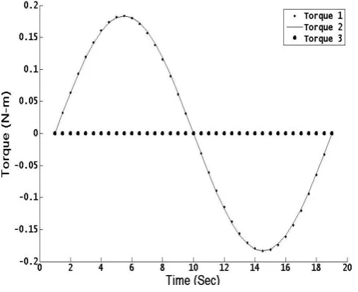
Case 1: Considering only motor 1 responsible for
circumduction (i.e. only motor 1 undergoes rotation and
motor 2 and motor 3 are disconnected), the torque developed by each motor w.r.t. time is shown in Fig. 3.
The motor 1 shows a steady torque rise with its peak value of torque 0.1836 N-m at time t = 5.5 seconds for quarter of the rotation due to load at the end of link 3 and in the next quarter, it drops to zero torque at time t = 10 seconds. The torque drops to maximum value with negative value at time t = 14.5 seconds and back to zero torque at time t = 19 seconds. It starts rising again at completion of one revolution following sinusoidal pattern. This means that the motor behaves in a normal manner related to servo motor architecture even when the mass is increased.
[image:3.595.303.549.49.258.2]The trend of torque for motor 2 is same to that of motor 1 whereas the motor 3 has zero torque.
Fig 3 Only motor 1 is rotating and motor 2 and motor 3 are disconnected
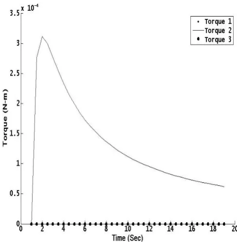
Case 2: Considering motor 2 responsible for pronation and
supination (i.e. only motor 2 undergoes rotation and the
remaining motors (motor 1 and motor 3) are disconnected, it is observed that the torque shoots sharply upto a value of 3.11x10⁻⁴ N-m at time t = 2 seconds (as shown in Fig. 4) and the drops to 6.5X10⁻⁵ N-m at t= 19 seconds. The result is same to that of R. Shadmehr and M. A. Arbib[1].
Fig 4 Only motor 2 is rotating and motor 1 and motor 3 are disconnected
But the torque for motor 1 and motor 3 remains almost zero, i.e. no torque is required to balance the torque for motor 2 as it is very small.
Case 3: Considering only motor 3 responsible for abduction
and adduction (i.e. only motor 3 undergoes rotation and
[image:3.595.303.547.391.645.2]Fig 5 Only motor 3 is rotating and motor 1 and motor 2 are disconnected
Case 4: When only motors 1 & 2 are rotating and motor 3 is disconnected, the trend for torques is same to that depicted
in case 1 as shown in Fig. 6. The effect of rotation of motor 2 (as shown in case 2), is negligible as compared to torque of motor 1. Hence, the resultant torque of each motor has no effect of rotation of motor 2.
Fig 6 When only motors 1 & 2 are rotating and motor 3 is disconnected
Case 5: When only motors 1 & 3 are rotating and motor 2 is disconnected, motor 1 and motor 2 has same trend for torque
[image:4.595.47.290.50.258.2]as depicted in case 1, as shown in Fig. 7, with maximum value of torque at time t = 5.5 seconds and t = 14.5 seconds with a value 0.1836 N-m and zero torque at time t = 10 seconds. Rotation of motor 3 has to balance the generated torques of motor 1 & motor 2. The trend of graphs for torque of motor 3 is maximum at time t = 7.0 seconds and 13.0 seconds with a maximum value 0.4766 N-m (which is almost equal to sum of torque of motor 1 and motor 2) and zero torque at time t= 10 seconds.
Fig 7 When only motors 1 & 3 are rotating and motor 2 is disconnected
Case 6: When only motors 2 & 3 are rotating and motor 1 is
disconnected, the trend for motor 2 has double frequency
with increasing peak values for torques (i.e. 2.56X10⁻⁴ N-m, 3.57X10⁻⁴ N-m, 3.54X10⁻⁴ N-m) at time t= 1.5 seconds, 8.0 seconds and 17.0 seconds and minimum values (i.e. 8.2X10⁻⁵ N-m and 2.47X10⁻⁴ N-m at time t= 4.0 seconds and 14.5 seconds), as shown in Fig. 8. The torque for motor 2 has the same trend as that depicted in case 2 with maximum value of torque (i.e. 2.59X10⁻⁴ N-m) at time t = 2.0 seconds. The motor 1 has zero torque as it is not rotating. The rotation of both motors motor 2 and motor 3 has negligible effect on motor 1.
Fig 8 When only motors 2 & 3 are rotating and motor 1 is disconnected
Case 7: When all motors 1, 2 & 3 are rotating, the trend for
[image:4.595.46.300.376.583.2] [image:4.595.307.548.460.658.2]Fig 9 When all motors 1, 2 & 3 are rotating
IV. CONCLUSION
From the graphs of the torque obtained for each motor separately and the combinations possible, it is observed that the maximum torque is encountered by motor 3, whereas, motor 2 and motor 1, which make the base of the arrangement, encounters minimum torque (discussed at length in the results). The arrangement of the motors is suitable for the working of the shoulder joint and can be thought of using it for rehabilitation.
ABBREVIATIONS DOF : Degree of freedom
R : Revolute
Ii : Moment of Inertia at ith motor M : Mass attached at the end of link 3 KEi : Kinetic Energy of ith link
PEi : Potential Energy of ith link θi : Angle of rotation of ith link T : Time of rotation
i : Time derivative of angle θi i : Double time derivative of angle θi τi : Torque of ith motor
REFERENCES
[1] R. Shadmehr and M.A. Arbib, “A mathematical analysis of the force-stiffness characteristics of muscles in control of a single joint system”,
Biological Cybemetics, vol. 66, pp. 463-477, 1992.
[2] K. T. Mohamed, S. S. Asfour, M. A. Moustafa and H. A. Elgamal, “A Computerized Dynamic Biomechanical Model of the Human Shoulder Complex”, Computers and Industrial Engineering, Elsevier, vol 31, No. 1/2, pp. 503 - 506,1996.
[3] B. Hannaford, J. M. Winters, C-P. Chou and P-H. Marbot, 1995, “The Anthroform Biorobotic Arm: A system for the study of spinal circuits”, Annals of Biomedical Engineering, vol 23, pp. 399-408,
March 1995.
[4] M. E. Rosheim, “Robot Evolution: The Development of
Anthrobotics”, New York, Wiley, 1994.
[5] J. Lenarcic, M. Stanisic and V. Parenti-Castelli, “Kinematic design of a humanoid robotic shoulder complex”, in Proc. of the 2000, IEEE
International Conference on Robotics & Automation, San Francisco, CA, April 2000, pp. 27-32.
[6] J. Lenarcic and M. Stanisic, “A humanoid shoulder complex and the humeral pointing kinematics”, IEEE Transactions on Robotics and Automation, vol. 19, No. 3, pp. 499-506, June 2003.
[7] E. Shammas, A. Wolf and H. Choset, “Three degrees-of-freedom
joint for spatial hyper-redundant robots”, Mechanism and Machine Theory, vol. 41, pp. 170–190, 2006.
[8] N. Klopcar, M. Tomsic and J. Lenarcic,“A kinematic model of the shoulder complex to evaluate the arm-reachable workspace”, Journal of Biomechanics, vol. 40, pp. 86–91, 2007.
[9] S. J. Ball, I. E. Brown and S. H. Scott, “A planar 3DOF robotic exoskeleton for rehabilitation and assessment”, in Proc. of the 29th Annual International Conference of the IEEE EMBS, Cité
Internationale, Lyon, France, August 23-26, 2007, pp. 4024-4027.
[10] S. Staicu, “Dynamics of a 3-RRR Spherical Parallel Mechanism
Based on Principle of Virtual Powers”, in 12thIFToMM World Congress, Besançon (France), 2007.
[11] W. Chen, C. Xiong, R. Sun and Xiaolin Huang, “On the Design of Exoskeleton Rehabilitation Robot with Ergonomic Shoulder Actuation Mechanism”, in Second International Conference, ICIRA 2009, Intelligent Robotics and Applications, Singapore, December 16-18.
[12] S. Sen, R. Abboud, W. Wang, D. Ming, B. Wan, Y. Liao and Q.