MIMO System for Matrix Decomposition to Study
Behavior of Antenna Beam Formers
Deepika Rana1, Birinderjit Singh Kalyan2 1, 2
Chandigarh University, Mohali, Punjab, India
Abstract: In MIMO system applicable for Matrix decomposition specify for transformation of a matrix and convert to diagonal based canonical structure. The motivations behind matrix decomposition and dimensional reduction investigative straightforwardness and computational comfort. Matrix decomposition concludes as a essential presentations in scientific based method due to its scientific and designing note worthiness. Working with extensive size matrices and the redundant idea of the calculations restrict us from getting the genuine arrangements in a coveted measure for time. Now changing over a troublesome matrix calculation issue into a few simple calculation issues enormously encourages the count exertion. Due to matrix decomposition for pre-defined matrix, which find subsequent matrices, have lower-rank based and minimize central position form and support uncovering the intrinsic trademark and structure of the matrices and help deciphering for various meaning. Adaptive Recursive Least mean squares (ARLMS) algorithms are a class of adaptive filter used to mirror a coveted filter by finding the filter coefficients that identify with
delivering the LMS of the error signal. This thesis uses the QR decomposition method to decompose the covariance matrix of the RLS algorithm to improve the overall beamforming of the smart antenna array. The system has also been simulated using MATLAB 2014Ra tool
Keywords: ARLMS, QR, Smart antenna , ALS, matrix decomposition , RLS
I. INTRODUCTION
Closeness of meddling signals and clamor signals are the characteristics of spatially spreading signals. In the event that the coveted signal and the obstructers involve a resembling worldly recurrence band, at that point fleeting filtering cannot not employed to separate the signal from the obstructers. Nevertheless, the meddling and the coveted signals usually commence from various spatial areas. During the intervening time, in randomly fluctuating portable communication condition negative impacts such as Doppler Effect, multipath fading, co-channel and orthogonal interference can occur. A current plan innovation called smart antenna is there to offer the solutions for the formerly referenced issues.
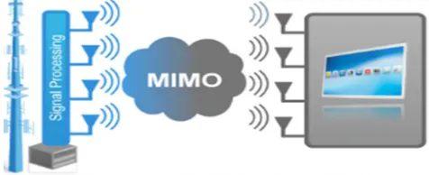
[image:1.612.185.423.521.618.2]In accord with the most fashionable idea, the use of remote strategies in different communication learning, and there is a never-ending demand for scaling down and thickness remote electronic devices and additionally increased data rate of selected devices.
Figure 1: Multi-Input Multi-Output (MIMO) Antenna
Figure 2: Concept of Smart Antenna
The general idea of smart antenna illustrated in Figure 2. The bar design created by a staged exhibit antenna able to controlled electronically to put the locale of most prominent affectability towards a wellspring of intrigue, and nulls in the headings of conceptual interferers.
II. PROBLEM STATEMENT
From extensive literature review, it has been concluded that smart antennas can be used to address various issues like multipath fading, co-channel interference and Doppler effects. Adaptation of filter weights can be realized by using various adaptive algorithms. But from literature study, the QR-RLS algorithm, due to its less numerical complexity, has been found to be most suitable for adaptation. The smart antennas can be used to address various issues like multipath fading, co-channel interference and Doppler effects. The RLS (recursive least square) algorithm apply only for fractional difference which is not appropriate for beam forming algorithms for smart antenna system that cannot be provides fastest convergence. Adaptation of filter weights can be realized by using various adaptive algorithms which due to its less numerical complexity, has been found to be most suitable for adaptation. [50]
III. VARIOUS ALGORITHMS TO STUDY ANTENNA BEAM FORMER
A. Adaptive Beam former Algorithms For Smart Antennas
Adaptation algorithms that change the adaptive filters coefficients keeping in mind the end goal to limit the related error standard. In this part, we have talked about the two fundamental adaption algorithms recursive least square (RLS) algorithms and least mean square (LMS). These two common algorithms that have discovered across the board application are least squares .LMS algorithm is a straight adaptive filtering algorithm which includes the programmed alteration of the Parameter of the filter as per estimation error. RLS algorithm has been utilized as a part of adaptive filters to discover the filter coefficients that identify with recursively creating the least squares of the error signal and gauge the coveted yield comes about .These algorithms to lessen the mean square between the information reference signal and signal. We have likewise talked about formulation of the LMS algorithm, convergence and dependability of the LMS algorithm and RLS algorithm.
B. The Approach For Least Mean Square Technique
The (LMS) calculation, exhibited by Widrow follow for in 1959 is a versatile calculation, which uses a slant based method for dimension not all that terrible. This calculation makes the use of the assessments of the slant vector from the accessible information. LMS fuses an iterative technique that makes dynamic redresses to the weight vector toward the negative of the point vector which definitely prompts the base mean square blunder [12].
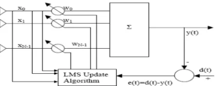
Uniform Linear Array (ULA) with N isotropic components that shapes indispensable piece of the versatile beamforming framework as appeared in the Fig.3 beneath.
[image:2.612.199.408.629.713.2]The output of the antenna array x(t) is given by:
(t) Indicates the coveted signal arriving at angle θ0and ui (t) signifies meddling signals arriving at angle of occurrences θi individually. a(θ0) and a(θi) speaks to the guiding vectors for the coveted signal and meddling signals individually in accordance to construct the coveted signal from the received signal in the midst of the meddling signal and extra clamor n(t), it is required. [13].
C. Recursive Least Squares
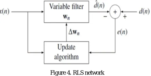
[image:3.612.174.433.268.399.2]RLS (figure 4) calculation is used as a piece of versatile channels to find the channel coefficients that identify with recursively flag (differentiate between the pined for and the bona fide flag) and gauge the pined for yield occurs. This is differentiation to various calculations that intend to lessen the mean square blunder. The refinement is that RLS channels are liable to the signs themselves, however MSE channels are data and needed signs. If these measurements are known, a MSE channel with settled co-successful (i.e., independent of the approaching information) can be built [16].
Figure 4. RLS network
IV. MATRIX DECOMPOSITION
Matrix decomposition, also known as matrix factorization alludes to the transformation of a matrix into a canonical form in the mathematical train of straight variable based math [21]. Matrix decomposition has essential applications in scientific computing in light of its scientific and designing criticalness. The motivations behind matrix decomposition are investigative straightforwardness and computational convenience. Working with expansive size matrices and the redundant nature of the computations deny us from getting the real arrangements in a coveted measure of time and inalienable trademark and structure of the matrices and help translating their meaning. There are a few distinctive decomposition procedures, which has arrangements in various techniques. The decision of best decomposition method is the method which uses Gram-Schmidt orthonormalization technique and decomposes a matrix into an and a triangular matrix and orthogonal matrix. In the application of signal handling and decomposition, QR decomposition is broadly utilized. The most vital applications of QR decomposition are adaptive pillar forming, filtering applications and OFDM, particularly OFDM-MIMO, applications.
V. PROPOSED ARLS ALGORITHM
A. Introduction
Versatile weight figuring utilizing the arls calculation is an entrenched strategy for flag handling applications, for example, beam forming ,evening out ,advanced predistortion .In this part we have talked about QRD-RLS calculation and CORDIC based QR disintegration .we utilize CORDIC to diminish the execution cost.
B. Algorithm Details
transmitter and the recipient. Every reception apparatus all the while transmits a little bit of information utilizing a similar recurrence band to the recipient. By exploiting the spatial assorted variety coming about because of spatially isolated reception apparatuses, the recipient can process the information streams and set up them back together. This system uses the transfer speed productively MIMO channels progress toward becoming recurrence particular amid high information rate transmission due to the multipath attributes of the earth. By joining OFDM and MIMO, these recurrence particular channels can be changed to a sef of recurrence level MIMO channels. Subsequently diminishing the beneficiary intricacy. Consequently, MIMO-OFDM frameworks are extremely encouraging in broadband remote systems[26].Each beneficiary in MIMO-OFDM frameworks ought to even out the got signal to evacuate the impact of channel on the signal.
Framework disintegration based slightest squares plans, for example, LU, SVD and QR-deteriorations stay away from unequivocal grid reversals and are more powerful and appropriate for equipment execution.
[image:4.612.184.433.276.362.2]FPGAs are the favored equipment stage for such applications as a result of their capacity to convey tremendous flag preparing data transmission. As of late, FPGAs have turned out to be accessible with progressively intense implanted delicate processor centers that give creators the adaptability and conveyability of abnormal state programming outline, while keeping up the execution advantages of parallel equipment activities in FPGAs [27] .
Figure 5. QR Decomposition Based Least Square
As described in figure 5 QR decomposition I used to transform X matrix into upper triangular matrix R(N x N) and vector Y to another vector U such that RC=U. Thereafter coefficient C is calculated by back substitution method which involves solving equations.
VI. DIFFERENT BEHAVIOR OF SMART ANTENNA BEAM FORMER USING MATLAB.
The adaptive beam former has been implemented for four antennas and Virtex 2Pxc2vp30-7ff896 and FPGA device has been used for its implementation.
MATLAB 2014 Ra and Virtex 2Pxc2vp30-7ff896 FPGA device has been specifically used to compare the performance of our implementation with implementation of the same adaptive beamformer by [11], used to implement. For the proposed design input signal frequency has been taken as 6 GHz and has been sampled at a rate of 100 GHz.[47]
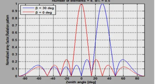
In Proposed algorithm space between the element play an important role in beam forming and it is taken as 0.9 lemda. Where number of array element -20, 0 and 20, desired user is arriving at 0 degree, interference angle of -20 degree by keeping spacing distance “d” constant and forgetting factor 0.95.
[image:4.612.182.432.581.718.2]In figure 6 ,space between the array element play an important role in beam forming technique and it is taken as 0 to -70 radiation pattern Where number of array element 0, 20 and 40, desired user is arriving at 0 degree, interference angle of -30 degree by keeping spacing distance “d” constant and forgetting factor 0.95.
Figure 7 Radiation pattern in dB at beta=0 and 30 degree.
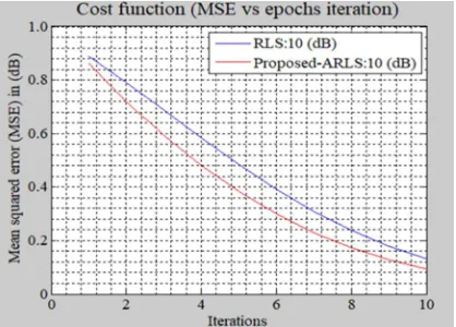
Figure 8. Mean square error plot for proposed ARLS approach at 10 dB variance and existing approach RLS
Fig 8 shows the desired signal corrupted with the mean square error.
Comparing Fig 6 and 7, it has been concluded that the interfering signal has resulted in an undesired peak in the spectrum, which should be removed by using adaptive beamformer.
Fig 7 shows the output spectrum of broadside array antenna consisting of four antennas without applying beamforming.
VII. CONCLUSION
In this research paper, there are different methods which can be used to Given rotation is preferred because its stability and accuracy are good for other methods.
QR decomposition using given rotations increase robustness, reduced complexity, reduce resource utilization in FPGA implementation and a possible VLSI implementation is modular structure. It was verified how adaptive algorithms are employed to adjust the coefficients of a digital filter. In particular the rate of convergence of RLS algorithm is faster than that of LMS algorithm, because the RLS algorithm utilizes all the information contained in the input data from the start of the adaptation up to the present. RLS algorithm is preferred for its faster convergence. The main disadvantage of RLS algorithm is that, the implementation of RLS algorithm requires large number of FPGA resources, so to reduce the large no FPGA resources, we use QR decomposition.
REFERENCES
[1] S. Applebaum, “Adaptive arrays,” Technical Report SPL TR-66-001, Syracuse Univ. Rec., Corp. Report, 1965 [2] J. Litva, T. K. Lo, “Digital Beamforming in Wireless Communications,” Artech House, Norwood, 1996
[3] A. J. Goldsmith, S. G. Chua, “ Variable-Rate Variable-Power MQAM for Fading Channels,” IEEE Trans. Commun., vol. 45, pp. 1218-1230, October 1997 [4] A. Goldsmith and P. Varaiya, “Capacity of fading channels with channel side information,” IEEE Trans. Inform. Theory, vol. 43, pp. 1986-1992, 1997 [5] Y. Ko and C. Tepedelenlioglu, ”Comparison of Adaptive Beamforming and Adaptive OSTBC with Outdated Channel Feedback,” IEEE Conference Record of
the Thirty-Eighth Asilomar Conference on Signals, Systems and Computers, vol. 1, 7-10, pp.1232 – 1236, Nov. 2004
[image:5.612.203.412.270.420.2]Commun., vol. 3, pp. 2097-2107, Nov. 2004
[7] B.D. Van, K. M. Buckley, “Beamforming: A Versatile Approach to Spatial Filtering,”, IEEE ASP Magazine, pp. 4- 24, April 1988
[8] L. C. Godara, “Applications of Antenna Arrays to Mobile Communications, PartI: Performance Improvement, Feasibility, and System Considerations,” in Proc. IEEE , vol. 85, pp. 1031-1060, July 1997
[9] L. C. Godara, “Applications of Antenna Arrays to Mobile Communications, PartII: Beam-Forming and Direction-of-Arrival Considerations,” in Proc. IEEE, vol. 85, pp. 1195-1245, August 1997
[10] W.J. Krzysztofik, M. Fafara, ”Comparison & Examination the Mtehods of Direction-of-Arrival Estimation,” IEEE Antennas & Propagation Society International Symposium, vol. 4a, pp. 154-157, 3-8 July 2005
[11] S. il Kwak, Kihun Chang, and Y. J. Yoon, 2005, Ultra-wide band Spiral Shaped Small Antenna for the Biomedical Telemetry, Asia Pacific Microwave Conference, 2005, Vol 1.
[12] C. M. Lee, Tzong-Chee Yo, and Ching-Hsing Luo, 2006, Compact Broadband Stacked Implantable Antenna for Biotelemetry with Medical Devices, IEEE Annual Wireless and Microwave Technology Conference, pp. 1-5.
[13] J. Wang, Osamu Fujiwara and Soichi Watanabe, 2006, Approximation of Aging Effect on Dielectric Tissue Properties for SAR Assessment of Mobile Telephones, IEEE Transactions on Electromagnetic Compatibility, Vol. 48, No. 2, pp 408-413.
[14] Z. N. Chen, Ailian Cai, Terence S. P. See, Xianming Qing and Michael Yan Wah Chia, 2006, Small Planar UWB Antennas in Proximity of the Human Head, IEEE Transactions on Microwave Theory And Techniques, Vol. 54, No. 4, pp 1846-1857.
[15] M. Klemm and G. Troester, 2006, EM energy absorption in the human body tissues due to UWB antennas, Progress in Electromagnetic Research, Vol. 62, pp. 261–280.
[16] N. Gopalswami, I. Osorio, S. Kulikov, S. Buyko, A. Martynov, and A. C. Raptis, 2007, SAW microsensor brain implant for prediction and monitoring of seizures, IEEE Sens. J., Vol. 7, No. 7, pp. 977–982.
[17] H. Yu, G. S. Irby, D. M. Peterson, M. T. Nguyen, G. Flores, N. Euliano, and R. Bashirullah, 2007, Printed Capsule Antenna for Medication Compliance Monitoring, Electronics Letters, Vol. 43, No. 22.
[18] K. Jiao, G. Zhao, F. S. Zhang, H. W. Yuan, and Y. C. Jiao, 2007, A broadband CPW-fed T-shape slot antenna, Progress In Electromagnetics Research, Vol. 76, pp. 237-242.
[19] M. R. Yuce , Wentai Liu, Moo Sung Chae, and Jung Suk Kim, 2007, A Wideband Telemetry Unit for Multi-Channel Neural Recording Systems, IEEE International Conference on Ultra-Wideband, pp. 612-617.
[20] K. Wang, 2008, SA/SAR analysis for multiple UWB pulse exposure, in Asia–Pacific Electromagnetic. Compat. Symp./19th Int. Electromagnetic. Compat. Symp., Zurich, Switzerland, pp. 212–215.
[21] D. D. Krishna, M. Gopikrishna, and C. K. Aanandan, 2008, CPW-fed Koch Fractal Slot Antenna for WLAN/WiMAX Applications, IEEE Antennas and Wireless Propagation Letters, Vol.7, pp. 389- 392.
[22] Y. K. Choukiker, S. K. Behera, and R. Jyoti, 2012, Sectoral Sierpinski Gasket Fractal Antenna for Wireless LAN Applications, International Journal of RF and Microwave Computer-Aided Engineering, Vol. 22, No. 1, pp. 68-74.
[23] F. Viani, 2013, Dual-band Sierpinski Pre-Fractal Antenna for 2.4 GHz- References 117 WLAN and 800 MHz-LTE Wireless Devices, Progress In Electromagnetics Research C, PIERS, Vol. 35, pp. 63-71.
[24] D. Alptekin and R.W. Lau, 2014, Design and the Numerical Analysis of a Dual Band (MICS (Medical Implant Communications Service; 402-405MHz) and ISM (Industrial, Scientific and Medical; 2.4-2.48GHz)) implantable antenna which is planned to be inserted in the header of the medical device, Proc. IEEE, Vol. 89, pp. 93–102.
[25] Kiourti, K. Yami. And K. Kityoi, 2014, Design of a New Miniature Broadband Implantable Antenna and a Dual-Band on-Body Antenna are Presented Along with the Transmission Performance, in IEEE Antennas and Propagation Society International Symposium (APS/URSI), pp. 1-9.
[26] Dr K.R.Santha, Bharani Chakravarthy Chava , K.Bragadishwaran and K.Chandru, “FPGA Implementation and Resource Utilization for QRD-RLS Systolic Array for Signal Processing Applications,” in Proc. IEEE TENCON, pp. 1 – 5, 2009.
[27] Gholkar, V.A.;” Mean square convergence analysis of LMS algorithm (adaptive filters)” Electronics Letters, Vol. 26,pp. 1705-1706,27 Sept. 1990.
[28] Byung Goo Choi; Yong Wan Park; Jeong Hee Choi” The adaptive least mean square algorithm using several step size for multiuser detection”Vehicular Technology Conference,2000. Vol.6,pp. 2822-2825,24-28 Sept. 2000
[29] Das,D.P.;Mohapatra,S.R.;Routray,A.;Basu,T.K.;” Filtered-s LMS algorithm for multichannel active control of nonlinear noise processes”Audio Speech and Language Processing,IEEE Transactions, Vol. 14. pp. 1875-1880, 5 Sept. 2006
[30] S. Haykin, Adaptive Filter Theory. Prentice Hall, third ed. 2003
[31] Wen-Chun Yu; Neng-Yih Shih;” Bi-loop recursive least squares algorithm with forgetting factors” signal processing letters,IEEE Vol. 13,pp. 505-508, Aug. 2006
[32] Lin, J.; Ling, F.; Proakis, J.G.;” An optimal windowed recursive least squares algorithm for fading channel estimation” Circuits and System,1993.,ISCAS ’93 1993 IEEE international sysmposium.Vol.1,pp.734-737,May-1993.
[33] Yu Xingxing; Zhang Dali; Yan Pingfan;” Adaptive recursive least squares algorithm for joint FIR filtering and post-delay tracking in the process identification” Proceeding on Intelligent Processing Systems, 1997. ICIPS '97. 1997 IEEE International Conference, Vol. 1,pp.783-786,Oct.1997.
[34] MCWHIRTER. J.G.: ‘Algorithmic engineering in adaptive signal processing‘. IEEE Proc. F, pp. 226-232, 1992.
[35] Wang Wenhua; Wang Hongyu;” Recursive least squares algorithm for nonstationary random signal” Proceeding on Signal Processing, 1996., 3rd International Conference ,Vol.1,197-200,Oct.1996
[36] G.H.GOLUB, C. F. V. LOAN. “Matrix Computations”. The Johns Hopkins University Press, (1983). [37] GOLUB. G.H., and VAN LOAN, C.F.: “Matrix computations” (Johns Hopkins University Press, 2nd edn.)
[38] Harteneck, M.; Stewart, R.W.;” Adaptive IIR filtering using QR matrix decomposition” proceeding on Signal Processing,IEEE Transactions,Vol. 46pp.2562-2565,Sept 1998
[41] Lu, B.; Guosen Yue; Xiaodong Wang;” Performance analysis and design optimization of LDPC-coded MIMO OFDM systems” proceeding on Signal Processing, IEEE Transactions,Vol.52,pp.348-361,Feb.2004.
[42] A. Sergyienko, O. Maslennikov. “Implementation of Givens QRDecomposition in FPGA”. Springer Berlin / Heidelberg, (2002).
[43] Y. Guo. “Efficient VLSI architectures for recursive Vandermonde QR decomposition in broadband OFDM pre-distortion”. IEEE Wireless Communications and Networking Conference, (2005).
[44] D. Cescato, M. Borgmann, H. Bolcskei, J. Hansen, and A. Burg. “Interpolation-Based QR Decomposition in MIMO-OFDM Systems”. White Paper (2005). [45] Shepherd, T.J., and Mcwhirter, J.G.: ‘A systolic array for linearly constrained least squares optimisation’, in Moore, W.. Mccabe. A. Urquhart, R., (Eds):
‘Systolic Arrays’pp. 151-159,1987
[46] D. Bopanna, K. Dhanoa, J. Kempa. “FPGA based embedded processing architecture for the QRD-RLS algorithm”. 12th Annual IEEE Symposium on Field-Programmable Custom Computing Machines (2004).
[47] T. J. Shepherd and J. G. McWhirter, “Systolic adaptive beamforming,” in Radar Array Processing, S. Haykin, J. Litva, and T. J. Shepherd, Eds. Berlin, Heidelberg, Germany: Springer-Verlag, pp.153–247, 1993.
[48] C.M.Rader, “VLSI systolic arrays for adaptive nulling”, IEEE Sig.Proc.Mag, Vol.13, pp.29-49, 1996
[49] G.Lightbody, R.L.Walke, R.Woods,J.McCanny, “Novel mapping of a linear QR architecture”, Proc. ICASSP, vol IV, pp.1933-6, 1999
[50] Jonathan Rose Ian Kuon, Russel Tessier. FPGA architecture: Survey and challenges. Foundations and Trends in Electronic Design Automation, 2007.