Improving the Management Process of Work
Instruction Documents
Bachelor
thesis
Olivier Berghuis
Bachelor IEM, faculty BMS
3
Final Bachelor Thesis
Improving the management process of work instruction documents
A case study at the manufacturing company Aeronamic
October 29, 2018
Author
Olivier Berghuis
Bachelor Industrial Engineering and Management
University of Twente
Educational Institution
Hosting Company
University of Twente
Aeronamic BV.
Drienerlolaan 5
Planthofsweg 79
7522 NB, Enschede
7601 PJ, Almelo
The Netherlands
The Netherlands
Supervisor University of Twente
Supervisor Aeronamic
Prof.dr. M.E. Iacob
Ir. R. Blaauwgeers
Faculty BMS
Director Manufacturing
Engineering
Second examiner University of Twente
Dr. A.I. Aldea
Preface
This report that lays in front of you is the result of a very enjoyable and interesting time I had at Aeronamic, the host company where I did my research after the management process of work instruction documents. The approach of this research and the solutions found to improve the document management process, are all explained in this thesis. Aeronamic offered me a workspace where I carried out my research from May until August 2018.
I had a great time at Aeronamic, where I was warmly welcomed by the manufacturing engineering department. Aeronamic is a very well-organized organization that spends much care on waste elimination and other improvement projects. The products they make are of very high quality and very interesting to see. I was given the possibility to have a close look at the company’s business
processes and I felt that my opinion was valued.
During my research period I was supported actively by people from Aeronamic and the University of Twente, which I would like to thank for their support. To start, I would like to thank Ronny Blaauwgeers who was my supervisor during my research time at Aeronamic. Ronny was vey concerned with my progress and we shared thoughts daily, which significantly improved the outcome of this research. Ronny was not only a devoted manager that had great knowledge about the manufacturing and preparation process, but he was also a great mentor whit whom I was able to share experiences and have a laugh with during lunch breaks.
The second person I would like to thank is Tom Hofsté, who was a great help in finding my way in the company and especially with the system Aras. Tom was always available to answer my questions even though he was loaded with challenges himself.
On behalf of the University of Twente I was supervised by Maria Iacob and Adina Aldea. I really appreciate the support they gave me to turn this research, that was mostly practical at first, into a well-structured academic research with this thesis as the result. Therefore, I would like to give special thanks to Maria and Adina.
Finally, I would like to thank all the colleagues of the manufacturing engineering department and my fellow students that did an assignment for Aeronamic at the same time. It is a list of too many names to mention personally, but I learned form the experience of each one of them and they made my time at Aeronamic very enjoyable.
I hope you enjoy reading this thesis as much as I enjoyed my time at Aeronamic and writing it.
Olivier Berghuis
7
Management summary
Aeronamic manufactures high speed rotating parts and sub systems for the Aerospace industry. To meet the high-quality requirements of the aerospace authorities it is important to have a good work preparation process and a system that proves that products are created according to the aerospace regulations. At the Manufacturing Engineering department of Aeronamic, certified engineers create, review and release the work instructions documents, used by the operators on the shop floor. The goal of this research was to improve the document management process by making it more structured, more controllable and fully digital. The full digital document management process fits the ambition of Aeronamic to realize a paperless factory. This research shows that a better document management process can realize a paperless production process on the shop floor.
Aeronamic started working with a combination of two IT systems a couple of years ago. The ERP (Enterprise Resource Planning) system called Isah and the PLM (Product Lifecycle Management) system called Aras. The ambition of Aeronamic is to arrange Aras as the leading system for all manufacturing information including the management of work instruction documents. Therefore, the main research question is:
‘How can we improve the document management process at Aeronamic?’
To gain a good insight in the current process (IST) and the effect of paper files in the process, we decided to use Business Process Modelling and Notation (BPMN) to create workflows of the current process. By creating a workflow of the desired situation (SOLL) as well, we were able to perform a gap analysis (IST vs. SOLL). We made a distinction between the document preparation process within the Manufacturing Engineering department and the use of the documents on the shop floor. The document preparation process is explained in three phases, the creation, review and release phase.
In the theoretical framework we first reflect on the use of BPMN and learn how to correctly model business processes according to the BPMN method. We reflected on the use of PLM for the management of production documents as well before we decided to look for improvements in the document management process using Aras.
With the use of BPMN we started to analyze the current document creation, review and release process of two document types, the ATS (Aeronamic Technique Sheet) and the BV
(“Bewerkingsvoorschrift”). Both documents are linked to the process plan(s) of a product and needed for a specific production step or operation. Analyzing the processes of both documents showed us that there was no uniform way of creating, reviewing and releasing work instruction documents and documents were reviewed on paper. It was hard to measure the problem in clear figures like long lead times or high production cost, but the lack of uniformity and the use of paper resulted in some clear inefficiencies:
- Documents were stored in different locations and in different formats (ATS documents are stored after release in Aras. BV documents are stored in a map on the Aeronamic server)
- The uses of printed files in the review loop made the progress hard to trace.
- ATS documents are signed on paper for release and printed as frozen PDF for use by the operators
8 - Documents are created manually including the generation of document IDs and linking the
document to the related items, which is error sensitive.
- The storage of ATS documents in Aras involved the interference of the CMO (Configurations Management Officer) and an extra review loop
The use of paper, the number of manual tasks and the lack of support by a digital system, makes the entire process difficult to trace and sensitive for mistakes. Difficulties to trace documents and big chances of mistakes in the documents and therefore the need to improve the documents, can be time consuming and frustrating. Times needed to create documents and get them reviewed varies a lot, but it has no negative effect on the production lead times, because getting the product approved for production by the authorities takes even more time. Therefore, it was not needed to evaluate on lead times of documents in more detail to measure the process in time units.
We determined to evaluate the process on the use of paper and lack of support by a digital system that together are the cause for inefficiencies, sensitivity for mistakes and lack of traceability. Also, the registration of made chances and other historic records is very difficult with the use of paper files.
With the use of BPMN we were able to get a clear overview of the differences in the creation, review and release process of the ATS and BV documents. Comparing the workflows of the IST and SOLL situations helped us to find the focus points for improvement. Knowing these focus points, we started looking for possible ways to use Aras to improve the process.
We found possible solutions to improve the document management process at Aeronamic with a big role for three functionalities of Aras. Saving documents to Aras, distribute the documents digitally in Aras for review, digitally review the documents in Aras and release the documents automatically without the interference of the CMO can be made possible with the use of three tools.
Aras Office Connector
The Aras Office Connector makes it possible to create documents using the familiar interface of Microsoft Office Word, but controlled by Aras and directly saving the file to Aras. This tool supports automatic number generation and the use of templates.
Workflow in Aras
The use of digital workflows in Aras makes it possible to distribute documents digitally in Aras and assign review tasks to specific users. The workflow starts automatically when a document is saved to Aras.
Visual Collaboration
The Visual Collaboration tool offers the opportunity to digitally review the documents without the reviewers changing the content.
9 Just like in the work preparation process, the use of paper causes inefficiencies on the shop floor as well.
The information needed by the operators for production is presented using a shop traveler. The shop traveler is a ring binder containing the printed production order, including the linked documents. All the information in this shop traveler is presented using paper files which means that there is no direct link with the database. Operators must manually search for the documents that are referred to in the shop traveler. The ATS documents are retrieved directly from Aras by the operator. Since Aras is a management system it is not meant to be used as an user interface on the shop floor.
Electronic Shelve Labels
One of the running pilots at the assembly department at Aeronamic showed us an alternative way of presenting document to the operator using a barcode and a scanner. Combining this solution with the use of Electronic Shelve Labels (ESL) could be a good solution to improve the way information is distributed on the shop floor and make the process completely paperless. The ESL system is not used before on a production floor but could be very suitable.
Recommendations
The research showed big advantages of the implementation of the three tools within Aras to improve the document creation, review and release process. We could find any big disadvantages and therefore we would recommend Aeronamic to start working with Aras as their document management system for each document type using the tools as explained in this thesis.
After the implementation of this solution Aeronamic should focus on arranging the process plans within Aras. Managing the process plans in Aras is needed to make use of the barcodes for the digital distribution of information on the shop floor as explained in chapter 4 of this thesis.
After arranging the process plans in Aras, Aeronamic can start with further testing the possibilities of the use of Electronic Shelve Labels to present the needed production information to operators, in combination with the use of barcodes as explained in section 4.2 of this thesis. This recommendation is focused on the realization of a paperless manufacturing process. To be sure the use of ESL is suitable for the production process, Aeronamic is recommended to consult with a company called Pricer, that developed a system for retail businesses, like supermarkets, that uses ESL to present product information to customers.
10
Table of contents
Management summary ... 7
Terms and definitions ... 12
1. Introduction ... 14
Aeronamic ... 15
1.2 Problem statement... 16
1.2 Research goal ... 18
1.3 Norm versus Reality ... 18
1.4 Scope of the research ... 19
1.5 Stakeholders ... 19
1.6 Deliverables ... 20
1.7 Research approach ... 21
1.8 Research questions... 24
2. Theoretical framework ... 26
2.1 Enterprise Architecture ... 26
2.2 Business Process Modeling ... 26
2.3 Use of PLM ... 29
2.4 UML ... 29
3 Problem analysis ... 31
3.4 Current situation (IST) ... 31
3.2 Desired situation (SOLL) ... 46
3.3 Document distribution Process ... 51
4 Solution design ... 55
4.1 Suggested improvements for the creation, review and release process ... 56
4.1.1 Aras software structure ... 56
4.2 Suggested improvement for the document distribution process ... 70
5 Evaluation of suggested solution ... 75
6. Conclusion ... 78
6.1 Evaluation of research questions ... 78
6.2 Contribution to Aeronamic... 79
6.3 Contribution to science ... 79
6.4 Limitations and future work ... 80
11
References ... 83
Appendices ... 85
Appendix 1: Document types and authorized creators/reviewers ... 85
Appendix 2: Overview of BPMN symbols and notations... 86
Appendix 3: All workflow models including collapsed views of subprocesses ... 89
12 Terms and definitions
Table 1.1: Terms and definitions
Term Abbreviation Definition
Aeronamic AEC Name of the host company
Aeronamic Technique
Sheet ATS
The ATS is a work instruction document type that explains the operators how a technical process, within a production step, needs to be executed. The ATS is a very specific instruction for the execution of the process for a specific part.
Bewerkingsvoorschrift BV
The BV work instruction document explains operators how a certain production step needs to be prepared or the after treatment after a machining step. The
difference between the ATS and BV is that the BV are more general instructions with less risk, for example how to deburr the products that come out of the machine.
Configurations
Management officer CMO
The CMO is responsible for the Engineering configuration of the ICT systems at Aeronamic. The use of
configurations is explained in section 1.2
Engineering Change
Notice ECN
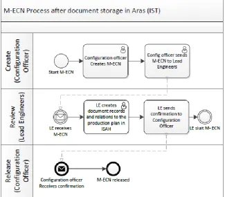
An ECN is created when the design of a product changes. The ECN is a notification that the impact of the change in the design to the configuration of data in the system, need to be evaluated and when needed changes need to be made.
Ist vs. Soll analyses
Ist vs. Soll are German terms that are commonly used to identify the evaluation of a change process. Ist vs. Soll means that the current situation (IST) is compared with a desired future situation (SOLL).
Lead Engineer LE
Lead Engineers are the certified engineers that prepare the manufacturing process for the products that are designed by the client.
Manufacturing Engineering Change Notice
M-ECN
The M-ECN is the notification that a change in the design of a product can possibly have an impact on the
manufacturing process and therefore the manufacturing configuration needs to be reviewed and changed.
Process Plan
Process Plan is the term used by Aras to name the list of all production steps needed to produce a certain product with the linked documents attached.
Product owner
The product owner is the Lead Engineer responsible for the successful creation of the product. This product owner has the most knowledge about the product and request of the client. The product owner is responsible for gathering all materials needed to create the process plan / routing to produce the product.
Production Order
13 Production Step
A production step is a station in the production process were a certain operation is executed before the product is send to the next production step.
Routing
Routing is the term used by Isah to name a possible sequence of production steps to produce certain products. Aeronamic for example produces rotors and turbine wheels which we call part groups. Within these part groups, individual parts have different characteristics but follow the same sequence of production steps. The details of the operations vary. The routing is a possible order of production steps that can be used as the base to create a production order that is part specific.
Shop traveler
The shop traveler is a ring binder filled with the production order and measuring data list. The shop traveler carries all the needed information or references to information files needed by the operators to produce a part. The shop traveler travels over the shop floor, along with the production batch that is linked to the production order. In section 3.3.1 more explanation about the essence of the shop traveler is given.
Special Process Specialist SPS
The SPS are certified engineers that are specialist in certain special production processes. The SPS is the only engineer that is certified to create ATS documents for the special technical production process he or she is certified for.
Werkkaartnummer A number that represents the relation between a production step for a certain production order. Bill of Materials BOM List with materials needed to create a product
Engineering Bill of Materials
E-BOM
The design is created by the client and the E-BOM shows which materials are needed according to this design. An example is the raw material needed for the part.
Manufacturing Bill of
Materials M-BOM
The M-BOM is the list of materials needed after the design of the client is translated to a production process at Aeronamic. Work instruction documents are an example of an item that can be present on the M-BOM but not on the E-BOM
14
1.
Introduction
This document is the final thesis of my bachelor study Industrial Engineering and Management at the University of Twente. For this thesis I had to find a bachelor assignment to graduate as a Bachelor of Science. After a short search I encountered Aeronamic. They were very happy to offer me an assignment focused on improving the document management process for work instruction documents created at the manufacturing engineering department of Aeronamic.
I got introduced to the problems around the current way of creating, reviewing and releasing the work instruction document used in production. During my problem analysis I realized that changing this process on the front hand, can also have an impact on the way these documents are distributed to and used on the shop floor. Aeronamic started a long-term project of continuous improvement five years ago. A lot of engineers followed courses to become black belt LEAN engineers. In the spirit of this continues improvement I found it important to not only limit my research to improving the document creation, review and release process but also understand how the possible improvements in this process can form a base for improvements in the way these instruction documents are used on the shop floor.
15 Aeronamic
Aeronamic develops, manufactures, test and maintains high-speed rotating systems for the aerospace industry. Aeronamic is a Dutch company located in Almelo with one extra facility in Sibiu Romania.
Aeronamic manufactures subsystems with highly accurate rotating parts for nearly three decades as this originally tied in well with the nature of the ultra-centrifuge manufacturing of Urenco Nederland B.V., its former parent company.
16
1.2
Problem
statement
The problem that I got introduced with at the Manufacturing Engineering department of Aeronamic, was that the current way of creating and reviewing work instruction documents for production was inefficient. The current way of preparing the work instruction document does not fit the ambition of Aeronamic and is therefore an improvement project that I was assigned to do for Aeronamic.
The Lead Engineers and Special Process Specialists, who create and review the documents, show their dissatisfaction with the current way of working. The creation and review process requires a lot of actions and the progress is difficult to track.
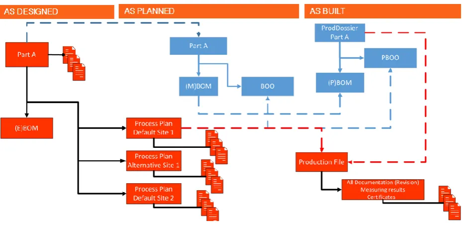
Aeronamic produces for the aerospace industry, so they must meet the Aerospace quality norm. To prove that the products are produced conform the aerospace quality norms, the entire production process is prepared, documented and tracked. The production process at Aeronamic is divided in three separate configurations, the As Designed, As Planned and As Built configuration. Figure 1.1 shows the configurations structure at Aeronamic
As Designed
The As Designed configuration is based on the design of the product that is created by the engineers of the client. Aeronamic processes the design and assignment from its clients in Aras. The product is stored in Aras as a part and all the materials needed according to the design are linked to the part. We call this list of needed materials the E-BOM, Engineering Bill of Materials. The Configurations Management Officer (CMO) at Aeronamic is responsible for the As Designed configuration.
As Planned
The As Planned configuration is the configuration in which the way Aeronamic addresses its resources to produce the by the customer designed part. In the As Planned phase the production routing is determined. The routing is a road map of the product through the shop floor from raw materials to product. Each production step including the related machine, tools, materials and time needed are planned before production. The resources needed to produce a product are listed in the Manufacturing Bill of Materials, or in short M-BOM. For each product a product specific routing is created by a certified engineer. At each production step certain activities need to be performed by the operators. These steps are explained in the different work instruction documents, for example the ATS (Aeronamic Technique Sheets) and the BV (‘Bewerkingsvoorschrift’ operation instructions). The package of documents, related to a production step, give the operator all the needed information to perform his task.
The As Planned configuration is most relevant for my research since I focused on the management of the documents that should be managed in the As Planned configuration.
As Built
17 production times, measurement data and other test data. Figure 1.1 shows the configurations structure at Aeronamic
Figure 1.1: Configurations structure
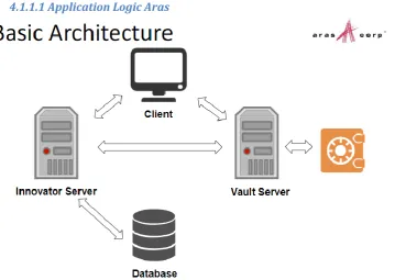
A good document management system is important to assure high quality production. Aeronamic has different information management systems that they use to manage all the manufacturing data, but the systems are not utilized by their full potential. Aeronamic has a Product Lifecycle Management system (PLM) called Aras, meant to manage all the manufacturing engineering and quality management data. Next to the PLM system Aeronamic uses an Enterprise Resource Planning systems (ERP) called ISAH, to manage all transactional data, production orders and ‘As Built’
production data. In the problem analysis chapter of this thesis I reflect more on the unused potential of mainly the PLM system.
In the current situation, work instruction documents are created manually by Lead Engineers or Special Process Specialists and printed for review by other Lead Engineers or the Quality and Development department. The use of paper documents is the reason for some of the problems that are time consuming and frustrating for the employees involved in the process. I listed some of the problems caused using paper in the preparation process below:
- Distributing and localizing the documents is difficult and time consuming - Many actions needed to print, sign and scan the documents
- Version control is difficult with paper documents
- Documents are frozen by scanning the documents as images. By doing so it is not possible to use any digital search functionality in the documents.
- No active link with database records of linked items.
Not only the use of paper, but also the process of manually creating the documents and its content creates room for errors. The engineers have freedom in their way of working because of the manual creation process. This is the cause for some of the problems. Problems that can occur because of the manual creation process are:
- Mistake with typing document numbers - Engineers create their own document types
- Documents are saved and stored in different forms and locations - Different formats of content
The problems all together make the process, both in the creation of documents as the use in production, time consuming and difficult to guarantee good quality.
Figure 1.2 shows the problem cluster of the document management process.
18 Figure 1.2: Problem cluster of the document management process
1.2 Research goal
The wishes at Aeronamic are to have a clear structured process of creating, reviewing and releasing production documents, managed digitally in the Product Lifecycle Management (PLM) system with active links to database records of linked items. Not only the creation, review and release of new documents must be a structured process, the change process of existing documents that need to be adjusted because of internal changes in the manufacturing process or external changes in the design of the product or international standards must be a clear structured process as well. My goal was to find a structured method for the entire document management process that suits the way of working at Aeronamic and adheres to Aeronamic’s translation of the aerospace regulations.
1.3 Norm versus Reality
The problem of the inefficient document management process is hard to translate to one measurable concept like long lead times or high production costs. A problem does not always have to be a difference in digits.
Aeronamic experiences a problem because they identified a gap in the wished and actual performance. Prostacos et al (2002) introduced us to the concept of performance imperatives. The performance imperatives are concepts that are valued by a company as essential elements to be competitive. Prostacos et al. stated that the two performance imperatives acknowledged by most production companies in 2002 were flexibility and innovations. This comes very close to the theory of
Charles Darwin that ‘the ones that are most adaptable to change are most likely to survive’. This
maybe is a little philosophic and off topic, but I believe that this nowadays is still applicable for most companies. Aeronamic understand that they must be flexible and already invest in experiments with innovative production methods. Aeronamic presented some desired outcomes to me as the norm, which is in line with the imperatives flexibility, productivity and innovation. The innovative goal for Aeronamic is to create a full digital factory.
Table 1.1 shows these wishes set against the current situation. I will reflect on the gap in performance between the desired situation (SOLL) and current situation (IST) in detail in chapter 3.
Many actions needed to print,
scan and sign
19 Table 1.1 Norm versus reality variables
Reality Norm
Every document is printed for review - Signatures set on paper with pen - Document brought on paper to reviewer by creator - Version control is difficult (is the paper copy the correct version?)
- Documents are frozen as images
No more use of paper copies to review documents - Digital signatures or alternative digital solutions for
prove of approval. - Digital distribution of documents for review
- At all time know the status of a document - Document revision numbers change automatically - Active link to related database records
Work instructions manually created in Word - Manually generating document number
- Very limited templates in Word for different documents - Creator scans document to freeze it and the
configuration officer stores the scanned pdf file in ARAS - Documents saved locally and at different locations
Work instructions directly generated in ARAS
- Automatically document number generating in ARAS - Templates in ARAS for different document types
- Creator creates, freezes and saves document in ARAS directly - Documents are all stored and managed within ARAS 1.4 Scope of the research
The future goal for Aeronamic is to have a content driven system instead of a document driven system. At the current situation documents are saved digitally but the content is not digital. Documents are saved as an image by scanning the paper file to a PDF format. The text is not recognized as text in the file and therefore the content is not digital. We agreed that investigating the possibilities to create a content driven system exceeded the scope of my research and therefore I did not focus on creating digital content. I focused on improving the way documents are created, reviewed and stored digitally, without the focus on digitalizing the actual content. I decided to include the reflection on the impact of the use of documents on the shop floor.
Aeronamic recently started working with Aras as their PLM system that communicates with their ERP system called ISAH. Aeronamic is still improving the way these systems are used and their wish is to continue working with these systems. During my research period I therefore did not investigate using possible other systems but focused on investigating whether these systems suit the needs of Aeronamic. My research is focused on how to design a new and more efficient way of creating, reviewing and releasing work instruction documents, using Aras as the data management system for the production documents.
I will limit the designed method to two of the documents, the ATS and the BV. An Overview of all document types is given in appendix 1. The ATS and the BV are both work instruction documents that are used in the routing of a part. After consulting with Ronny, we concluded that the differences between these two document types give a good insight in the problem. Finding a uniform method for these two types will give Aeronamic enough insight in the possible improvements for all documents.
1.5 Stakeholders
I will do my assignment for the manufacturing engineering department of Aeronamic. The assignment is focused on improving an internal process. To find a good solution for the improvement of the process it is important to understand who the stakeholders are and who will potentially benefit from the generated solution.
20 Different departments are involved in the different stages of the work preparation process. Table 1.2 shows the different departments involved related to the four stages.
Table 1.2: Stakeholders
Department
/Team Cycle stage Role and connection with work preparation
Lead
Engineers Creation, review and release
The Lead Engineers create the work instruction documents and are responsible that the right people review the instructions. After the review of for example the quality department, the Lead Engineer signs for final release and sends the document to the configuration officer or saves the document on the local server. Figure 3.1 shows the workflow of this process.
Quality Development Engineer
Review
QDE is responsible for the quality control loops within the manufacturing department of Aeronamic. They can review documents and judge whether all requirements are met.
Configurations Management Officer (CMO)
Release
For some documents the CMO is responsible for the storage of the document in the PLM system ARAS in the current situation. I will come back to this in chapter 3.
Operators Use
The operators are the target group for the work instructions. They are the ones who need to work with the documents and therefore need to have access to the right information at the right time. The right information needs to be presented in an understandable way.
As shown in table 1.2 multiple departments and employees relate to the work instruction documents lifecycle. The goal is that they will all benefit from a better and more efficient way of creating, reviewing and releasing the work instruction documents and the way the documents are presented to the operators.
Evidently one of the individual stakeholders, not mentioned in table 1.2, is de Director Manufacturing Engineering, Ronny Blaauwgeers who is responsible for the progress of the entire department. As my internal supervisor at Aeronamic he closely monitored my progress to make sure my proposed solution fits the norms and standards of Aeronamic.
1.6 Deliverables
The goal of my research is to find one uniform and digital way to create, review and release all work instruction documents, needed for production, and managed by the PLM system Aras. To show that the method I found is indeed a solution to the problem, I did a proof of concept for the digital distribution and review loop using Aras within the manufacturing engineering department for text documents. This report is written to explain and support my findings.
I also evaluated possible improvements of the distribution of the document on the shop floor because of the improvements of the digital management of the documents. I visualized a possible solution in this thesis.
21 analysis I made workflows of the document creation, review and release process, using the Business Process Modelling Notation, v2.0 of the Object Management Group (2011). I will provide Aeronamic with these models in presentation form to explain and enforce my findings.
1.7 Research approach
My research involves the use of Information Systems for the improvement of the document management process. I decided to use the Design Science Research Process (DSRP) method of Peffer (2006). Peffer concluded that little models exist concerning the use of design science for research after Information Systems. Peffer designed the DSRP model which supports researchers to carry out a design science research in a structured way and forms a model to present the research to readers and reviewers. Figure 1.3 shows the schematic view of the DSRP of Peffer (2006). The process model consists of six activities in a nominal sequence:
1. Problem identification and motivation
‘Define the specific research problem and justify the value of a solution. Since the problem definition will be used to develop an effective artifactual solution, it may be useful to atomize the problem conceptually so that the solution can capture the problem’s complexity. Justifying the value of a
solution accomplishes two things: it motivates the researcher and the audience of the research to pursue the solution and to accept the results and it helps to understand the reasoning associated
with the researcher’s understanding of the problem. Resources required for this activity include knowledge of the state of the problem and the importance of its solution.’
The use of paper causes a lot of inefficiencies in the document management process of Aeronamic. Figure 1.2 shows the problem cluster of the problem. The inefficient way of working does not fit the progressive vision of Aeronamic. The problem identification is all based on empirical data gathered by conducting interviews and observing the process.
2. Objectives of a solution
‘Infer the objectives of a solution from the problem definition. The objectives can be quantitative, e.g., terms in which a desirable solution would be better than current ones, or qualitative, e.g., where a new artifact is expected to support solutions to problems not hitherto addressed. The objectives should be inferred rationally from the problem specification. Resources required for this include knowledge of the state of problems and current solutions and their efficacy, if any.’
The objectives of a solution are given in section 1.2 and 1.3. The document management process must be fully supported within Aras and the use of paper most be excluded from the process. Table 1.1 shows the norm of the desired solution.
3. Design and development
‘Create the artifactual solution. Such artifacts are potentially, with each defined broadly, constructs, models, methods, or instantiations’, Hevner et al. (2004). This activity includes determining the
artifact’s desired functionality and its architecture and then creating the actual artifact. Resources
required moving from objectives to design and development include knowledge of theory that can be brought to bear as a solution.’
22 4. Demonstration
‘Demonstrate the efficacy of the artifact to solve the problem. This could involve its use in experimentation, simulation, a case study, proof, or other appropriate activity. Resources required for the demonstration include effective knowledge of how to use the artifact to solve the problem.’
For the demonstration of the suggested solution we did a proof of concept. The proof of concept is presented in chapter 4 of this thesis.
5. Evaluation.
‘Observe and measure how well the artifact supports a solution to the problem. This activity involves comparing the objectives of a solution to actual observed results from use of the artifact in the demonstration. It requires knowledge of relevant metrics and analysis techniques. Depending on the nature of the problem venue and the artifact, evaluation could include such items as a comparison of
the artifact’s functionality with the solution objectives from activity 2 above, objective quantitative performance measures, such as budgets or items produced satisfaction surveys, client feedback, or simulations. At the end of this activity, the researchers can decide whether to iterate back to step 3 to try to improve the effectiveness of the artifact or to continue to communication and leave further improvement to subsequent projects. The nature of the research venue may dictate whether such iteration is feasible or not.’
For the evaluation of our solution we used Business Process Modelling to compare the model of the suggested solution with the current situation. We use the selected norm in section 1.3 to reflect on the suggested solution.
6. Communication.
‘Communicate the problem and its importance, the artifact, its utility and novelty, the rigor of its design, and its effectiveness to researchers and other relevant audiences, such as practicing professionals, when appropriate. In scholarly research publications researchers might use the structure of this process to structure the paper, just as the nominal structure of an empirical research process (problem definition, literature review, hypothesis development, data collection, analysis, results, discussion, and conclusion) is a common structure for empirical research papers. Communication requires knowledge of the disciplinary culture.’
23
Figure 1.3: Design Science Research Design model by Peffer (2006)
Peffers design science research model can be used with different centers of approach. The process is structured in a nominal order, but it is not expected that every researcher follows the process in sequential order from activity 1 to 6. Researchers can start at almost every activity and move outward.
Objective centered Approach
24 1.7.1 Interviews
Part of the research approach to gather all the needed information, is conducting interviews with everybody participating, or otherwise involved, in the document management process. We will look critically at the empirical data that we gather with these interviews to lower the risk of bias. We will interview Lead Engineers, Special Process Specialists, Quality and development Engineers, Director Manufacturing Engineering and Operators. The different perspectives of these people should provide a good understanding of the process.
1.7.2 Literature Review
The focus of this research is to improve a business process. We will use Business Process models to do a performance analysis of the process. Literature about BPM and BPR (Business Process Re-engineering) will help us to understand how to create business process models and compare the current with the desired situation.
1.7.3 Desk Research
Next to the papers used to understand BPM we can use a lot of materials and information about the document management process at Aeronamic that are available within the company. Examples of research activities we can do at our desk at Aeronamic are: evaluate the work instruction documents, consult manuals of Aras, navigating through the systems Aras and walk the process of creating, reviewing and releasing a document.
1.8 Research questions
The research approach is meant to help me find the answers to the research questions in a structured way. The answers to these questions give me the needed information to find a solution for the core problem. In this section the research question and sub-questions that are prepared because of the problem identification are presented.
1.8.1 Main research question
In section 1.1 I explained the problem around the work preparation at the Manufacturing Engineering department. The most important action problem that was noticed by Ronny Blaauwgeers, Director Manufacturing Engineering, is that the current document creation, review and release process is inefficient. The core problem that we found is that documents are not managed with the support of a digital system. So, the main research question is:
‘How can we improve the document management process at Aeronamic?’
25 1.8.2 Sub-questions
1. How is the current document management process at Aeronamic arranged?
The answer to this question must tell us how documents are created, reviewed and released in the current situation and by whom. By investigating how the process works we evaluate which systems are used to support the process and what are the limitations. We need to understand the process of the current situation to find reasons for the problems and formulate possible solutions.
2. How can we model the current situation?
Modelling the business process can help us to evaluate the problem by presenting the process in an understandable and clear manner. Theory about business Process Modelling can help us in creating the models.
3. What elements are causing inefficiencies in the process?
The evaluation of the process must tell us what parts and elements of the process are the cause of the inefficiencies. Understanding the causes for the inefficiencies may help us to find solutions that realize the objectives set for this research.
4. What examples of solutions exist to improve document management?
After identifying the problems and reasons for inefficiencies we can focus on finding solutions to the problems. Theory about document management can help us find ways to improve the process. Given the large number of reports about the data management and the elimination of paper in production processes, Aeronamic is not the only company that is concerned with the improvement of document management. Consulting with other companies may help us in creating possible solutions.
5. How can we design a possible solution to realize the desired solution?
26
2.
Theoretical framework
To find answers to the research questions, especially 2 and 4, and evaluate the IST and SOLL situation, I used theory found by doing literature research.
2.1 Enterprise Architecture
The goal of the research is to improve a business process with the intention of using IT systems to make the process paperless. We will evaluate the use of an IT system as a structured element of the business. The concept of evaluating how a company is structured to perform its operations and reach its goals is called Enterprise Architecture. Enterprise Architecture’s focus is to set clear guidelines and principles how a business should operate and implement change. The structure of the company, its business processes, the information flow and the contribution of IT systems to the operations can be modelled using business process modeling techniques. Enterprise Architecture helps us to understand the coherence between the business operations and IT. Jelle (Value Blue). (2017). Wat is enterprise architectuur? and HORA. (2016). De rol van enterprise-architectuur. We did not make big changes in the IT structure of Aeronamic during our research, we focused on restructuring the current IT systems used by Aeronamic as we explain in chapter 4. Therefore, it is enough to understand the basic principle of Enterprise Architecture, but we will not dig any deeper into this concept. For the evaluation of business processes, including the support of IT systems we will, use theory about Business Process Modelling.
2.2 Business Process Modeling
Using business process models to get a better understanding of a certain process is an element of the Business Process Management discipline. Business processes are part of the operations needed to keep the company running and reach the company goals. ‘A business process is the combination of a set of activities within an enterprise with a structure describing their logical order and dependence whose objective is to produce a desired result.’(Aguilar-Savén R. S. (2003). Business process modelling).
Business Process models are used to generate a better understanding of the process and support the evaluation of its performance. Business Process Models are often used in a change process to compare models of the current situation with the desired situation. The creation and evaluation of these models with the intention of improving the process is called Business process re-engineering.
2.2.1 Business Process Re-engineering
Business process re-engineering (BPR) is a concept that came forth out of the need for companies to obtain drastic improvements to meet constantly increasing customer requirements.
‘The reengineering of business processes is concerned with fundamentally rethinking and redesigning business processes to obtain dramatic and sustaining improvements in quality, cost, service, lead times, outcomes, flexibility and innovation’ (Al-Mashari M., Irani Z., Zairi M. (2001). Business Process Reengineering: a survey of international experience)
Business process re-engineering or redesign is a well-known concept since the 1990’s and a lot of
27 despite the many examples of successful use of BPR, no uniform and clear approach exists. Their paper is meant to offer a heuristic approach for finding the best practice that suits our organizations by evaluating empirical data from a big set of companies.
2.2.2 BPMN
The use of Business Process Management was mostly based on heuristic rather than clear methodologies. In the last decade BPM developed into a mature discipline, with a well-established set of principles methods and tools that can be used to improve business processes (Van der Aalst M.P., La Rosa M., Santoro F. M. (2016). Business Process Management).
One of the tools for modelling business processes is the modelling languages, Business Process Model and Notation, in short BPMN. This is the latest developed modelling notation which is used by many bigger companies to model their business processes. The BPMN languages helps us to model business process following clear guidelines. This makes BPMN models understandable for more people than just the ones who created the models. The latest version of BPMN is BPMN 2.0.2 which was launched in December 2013. Figure 2.1 shows an example of a business process modeled using BPMN.
Figure 2.1: Business process modeled in BPMN 2.0
28 Workflow technique is one of the methods to model a business process. ‘A Workflow is a flow of
tasks between computer applications or people in an organization.’ (Aguilar-Savén. (2003)). Workflows are not only very useful to model business processes, workflows can be used to analyze and improve a business process by modelling the process. Software systems are developed to create, manage and execute workflows as a computer driven representation of the business process. Workflows support the analysis of a process by visualizing a business process in separate parts to get a quick overview of the process and the sequence of tasks. Workflow management is a very suitable way to model business processes that have both human as computer automated tasks.
For my research it was important to model the flow, order and amount of activities to find out if we can make the process more efficient and improve the quality by eliminating error sensitive activities. The control-flow perspective fits best with this goal but the research was not only about the order and quality of activities. During the process, data items are generated. We also evaluated the data process methods and the support of IT systems in this process. Therefore, it was important to use some principles of the data perspective in combination with the flow-control. The workflow models of the current and desired situation for the data management at Aras are presented in chapter 3.
The reason for the development of new and better modeling languages was the belief that better process and flow models result in better processes. The models were created to get a better insight in the business process and show this to relevant people within the company. Business process models are used, as mentioned before, to create and compare models of the current and desired situation. The idea behind the use of BPM changed in the last years. Important critique about the use of BPM is that the models were not connected to the actual process and. This causes two important shortages in the way BPM is used.
The models that are created for performance analysis may not resemble reality. The models can mainly be based on information of those who participate actively in the process because the creator is one of the participants in the process or all information is gathered by doing interviews. The result is that the models are influenced by knowledge bias, personal preferences or organizational norms (Van der Aalst. (2001))
Second, the models are rarely used in the implementation process of an automation solution. New conceptual processes are created using BPM, but little companies use BPM technology to run or support their processes. (Van der Aalst M. P., La Rosa M., Santoro F.M. (2016). Business Process Management). Most companies use standard systems or custom-made systems were processes are hard coded or not supported at all. BPM systems are experienced as too restrictive and very expensive; therefore, we do not expect that the little use of BPM technology will change soon.
29 2.3 Use of PLM
PLM is often used as a product information system. PLM systems are designed to manage all product information through its entire lifecycle, including the work instruction documents needed for production. Many companies use PLM in combination with ERP when they started with the digitalization of data management. Aeronamic uses this formula as well with Aras as their PLM system and ISAH as their ERP system. The study of the Aberdeen Group, Integrating PLM & ERP (2008) tells us that the integration of PLM with ERP is likely to be a good base for improvement of the business performance.
For a company like Aeronamic that work according to high quality standards, proper data management is very important. Not only to get the right documents with the correct revisions to the right operator at the right time, but also to manage the production data is very important to control the production process.
Some of the possible problems with the use of paper in production are mentioned in section 1.1. Aeronamic is not the first company that faces problems caused using paper in production. The goal for a lot of companies now and for the past few years is to realize a paperless factory. The use of PLM and ERP give Aeronamic the possibility to make their production a paperless process.
Documents are not distributed as paper copies for review and on the shop floor, but the use of PLM makes it possible to digitalize this workflow. All documents can be shown on screen by authorized users. Also, data like measuring result do not have to be filled in with pen on a paper sheet. PLM has the functionality to present the same sheet on screen, so the operator can fill in the data digitally. This way of working with digital files instead of paper documents is called paper on glass.
2.4 UML
The way the systems are used in the document management process is presented in the BPMN models, but the way these systems are arranged and operate is not shown in these models. For the modelling of the functionalities and structure of a software systems we can use a different modeling language that is called UML (Unified Modeling Language). UML is created to make the functionality of difficult software systems more understandable for everybody.
The goal of UML is to have a common and visual modeling language for the construction, the design and implementation of complex software systems, for the structure as well as the behavior of the software system (Lucid Software Inc, 2018). UML is no programming language, but it is used to analyze and design systems in an object-oriented way. UML describes the structure and the behavior of a system and the related objects.
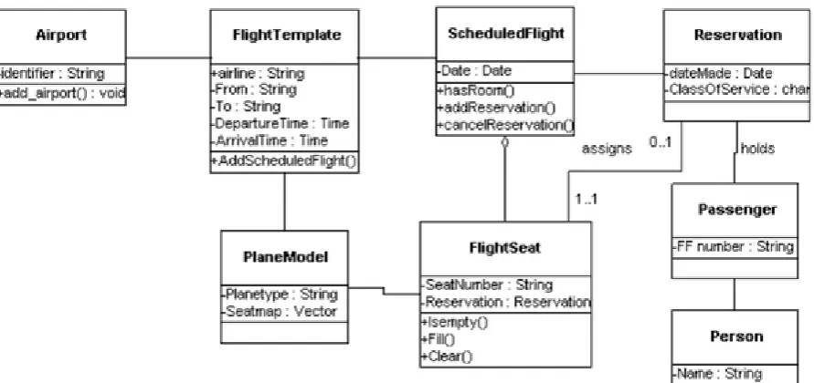
30 2.4.1 Class diagram
Class diagrams are a way to visualize the structure of classes and attributes within an information system using UML. For example, take a passenger that books a flight ticket at a certain airline. The passenger is an example of a class. Because the passenger is a general item. In a flight there can be more passengers that all have different characteristics. So, the passengers have attributes like a name, date of birth, age and address. When the passenger books a ticket for a flight he also gets the
attribute ‘flight number’ allocated. For every passenger the attributes can be different. A second
Class in this example can be ‘flights’. The airline has different flights to different locations at different
times. So, the class flight is filled with attributes like; flight number, plane type, departure time and arrival time.
[image:30.595.75.521.308.518.2]This example shows us how to organize data and information in a structured way. Figure 4.39 in chapter 4 shows the class diagram that shows how the documents and information can be managed at Aeronamic using the suggested solution. Figure 2.2 below shows the class diagram of the example of the ticket booking system.
31
3
Problem analysis
Now that we have presented the problem statement, formulated research questions and studied relevant literature, we can start with mapping the current situation to analyze the problem in more detail. In this chapter we will analyze the stated problem further by comparing business process models of the desired situation (SOLL) with models of the current situation (IST). The purpose for the evaluation of the workflows is to get a clear view of the steps that need to be taken and the way the documents are distributed and managed along the process. This IST vs. SOLL analysis helps us to identify the steps needed to improve the process. Next to the business process model of the desired situation we will also show a model of the process with a possible solution (figure 4.27) in chapter 4.
I gathered the information needed to understand the current situation by conducting interviews, look through the management system and Quality Management System of Aeronamic and my own observations.
The purpose for the evaluation of the workflows is to get a clear view of the steps that need to be taken and the way the documents are distributed and managed along the process. I did not use workflow creating software that support functionalities to simulate lead times and other
performance measures. After the interviews with multiple Lead Engineers I found out that the time to finish this process is not an important measure. The process to get the approval to start the actual production for a part takes a lot longer.
3.4 Current situation (IST)
As mentioned in the problem statement, Aeronamic produces with support of many instruction documents. These documents are created by Lead Engineers and Special Process Specialists. The creation of these documents is done manually using Microsoft Office Word and templates that are stored in the Aeronamic Management system. During the analysis of the problem I found out that different document types are created in different ways and stored in different places. This means that there is not one uniform method for creating reviewing and releasing of the different work instruction documents. In this chapter I will use the process of two document types as the base for my research. These are the Aeronamic Technique Sheet (ATS) and the ‘Bewerkingsvoorschrift (BV)’
(translated from Dutch: operations instruction). The difference in language for the names of document types is a very simple example of an inconsistency. Next to that the BV’s are stored as
Word files on the Aeronamic server under Manufacturing Engineering Data and the PDF file is stored in a different folder on the server. The ATS documents are saved as adjustable Word file and one PDF on the Aeronamic server, in a different folder structure than the BV, and the PDF file is stored in Aras.
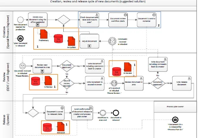
32 Figure 3.1: Main creation, review and release flow for each document
The type of document that must be created determines which engineer is authorized to create the document, who must review the document and if the document needs a second review loop. The creation and review rules for the documents are set up by the Quality Department of Aeronamic. Appendix 1 shows the authorized creators and reviewers per document type.
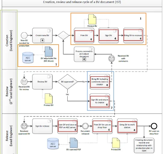
3.1.1 IST ‘Bewerkingsvoorschrift’
The BV document is an instruction for the operator how to use the tools and machines at the workstation to correctly perform the operation. Examples of BVs are an assembly instruction or deburr instruction. The BV is created by a Lead Engineer with the input of the operators, because they are the people with experience in practice. A second Lead Engineer reviews the BV. The released document is presented to the operator as a printed document and as a PDF file on the server. The printed document is stored in a drawer cabinet close to the work station.
The Word file is saved on the server. Everyone at the Manufacturing Engineering department of Aeronamic has access to the respective map on this server. The world files are not protected so if one of the Manufacturing Engineers wants to they could adjust it or accidentally delete the file. A frozen and signed PDF file of the BV is stored in another map on the server that is accessible for operators. This is because operators only use released files that are signed for approval. A second
reason that the PDF’s are stored in another folder is to prevent that the operators accidentally change the document while using them in production.
33
34 The main process model in figure 3.1 showed three main stages of the process: creation, review and release. These three stages determine the structure of all the business process models in this chapter. This structure is added to the model with the use of swimming lanes. Explanation about the symbols in the models can be found in appendix 1.
To keep the main models as short and clear as possible I used sub processes in the main model. When relevant we will take a closer look at the sub processes.
When evaluating the models, we look at four important elements:
1 The document format and storage location 2 The task types
3 The roles involved in the process
4 The amount of actions needed in the process
The moment in the process where we can see the impact of these four elements are highlighted with numbered and colored rectangles in figure 3.3.
3.1.1.1 Identified problems IST model BV
1. Document format and storage location
The IST model for the BV shows documents with two colors, blue and yellow. The blue documents represent a document that has a digital format but is not managed by Aras. The yellow documents represent paper files.
The model shows that a BV is printed for release, scanned to save the signed BV on the server and printed again for use on the shop floor. From the moment the document is printed it is impossible to track the document and the progress with live data. The document can get lost as well and you can never be shore that the paper document is the latest version. The printed BV is Work in Progress (WIP) that is very hard to register. The Word file is saved on the server. Everyone at the Manufacturing Engineering department of Aeronamic has access to the respective map on this server. The world files are not protected so if one of the Manufacturing Engineers wants to they could adjust it or accidentally delete the file. A frozen and signed PDF file of the BV is stored in another map on the server that is accessible for operators. A negative effect of scanning the document to freeze it as a PDF is that a scanned document is an image. In an image text is not recognized as text anymore. This makes it impossible for operators to use digital search tools like ‘ctrl+f’.
The document is not linked to an IT system and has a format that is not uniform and free to adjust. This gives the creator a lot of freedom to make changes and a mistake is easily made. Everyone could create a file with the name BV because there is a lack of a system that can correct this by recognizing the creator. When analyzing existing documents, I even found a few documents that were released by the same person that was the creator. That is the result of the freedom the engineers get using paper because it is hard to monitor changes that are made.
35 2. The task types
The model shows that every task in the process is a manual task. This is a result of the fact that the document is not managed by a digital system and causes the same problems as mentioned above.
One of the biggest mentioned problems of the manual tasks, is that it cost the engineer more time to create the document and control his own actions. For example, to determine the document number that must be unique, the engineer must look up the last created document. The document number of the new BV must be the number of the latest BV plus 1. This is a lot of work just to give the document a number.
Manual tasks are not supported by any digital system. Therefore, there is no link with database records and no system will correct mistakes made during the task.
3. The roles involved in the process
The creation of the BV is simple if you look at the roles involved. A Lead Engineer creates the BV and a second Lead Engineers reviews the BV. If the second Lead Engineer approves the document the first Lead Engineer signs for release. The BV is seen as a low risk document, because it is not an instruction document for a special process that is determined by the customer and needs to be executed by a certified operator. Therefore, a single reviewer is considered sufficient.
4. The number of tasks needed in the process
The main process shows a lot of actions needed to print, sign and distribute documents before and after release. Although good prepared documents are very important for Aeronamic, these actions do not add any value to the product. All these time-consuming actions are non-value-added actions (NVA). The tasks to create review and release documents are all NVA so it is important to make this process as efficient as possible.
3.1.1.2 Important findings
The most important reasons for inefficiency in this process are:
- The creation process is error sensitive
- The use of paper documents in the review loop causes time consuming actions - The WIP is difficult to trace
36
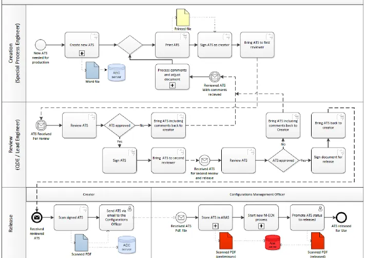
37 3.1.2 IST Aeronamic Technique Sheet
The Aeronamic technique sheets are instructions for a certain production step. ATS is the classification of a work instruction document for a technical operation that is part of the production process planned to meet the customers design standards. The ATS documents can be classified per operation using sub types. Appendix 2 shows an overview of the documents with type ATS and the subtypes.
ATS documents are written for every technical production process including the special processes. The Technical Process Specialists are responsible for the special processes. They are the only engineers that are allowed to create ATS documents for the special processes. The ATS documents are reviewed by a Lead Engineer and the Quality Development department. The reason for the double review loop is the importance of the documents. As mentioned in section 1.2 the documents used in production are not only an instruction for the operators, they are the proof that Aeronamic produces following the aerospace norm. The Quality and Development department of Aeronamic is responsible that production adheres to the aerospace norm. Quality and Development therefore reviews the ATS documents on clarity, structure and correct referencing. The Lead Engineers review the documents on content and terminology.
In contradiction to the BV the ATS documents are not used on the shop floor as printed documents. The ATS documents are saved as Word files and a nonadjustable PDF with revision number at the same server domain as the BV word files. This PDF file is, unlike the PDF file of the BV on the server, not signed yet. The signed and scanned PDF files of the ATS documents are not stored on the server. These documents are stored as a document item in Aras by the Configurations Management Officer (CMO). The operators retrieve the required ATS from Aras. The way the documents are retrieved form Aras is evaluated in more detail at the end of this chapter. First let us have a look at the current creation, review and release process of ATS documents.
38