warwick.ac.uk/lib-publications
Original citation:
Trushkevych, Oksana, Collings, Neil, Crossland, William A. and Wilkinson, Timothy D.. (2006) Resolution in optically addressed spatial light modulators based on dye-doped liquid crystals. Applied Optics, 45 (35). pp. 8889-8892.
Permanent WRAP URL:
http://wrap.warwick.ac.uk/92167
Copyright and reuse:
The Warwick Research Archive Portal (WRAP) makes this work by researchers of the University of Warwick available open access under the following conditions. Copyright © and all moral rights to the version of the paper presented here belong to the individual author(s) and/or other copyright owners. To the extent reasonable and practicable the material made available in WRAP has been checked for eligibility before being made available.
Copies of full items can be used for personal research or study, educational, or not-for-profit purposes without prior permission or charge. Provided that the authors, title and full
bibliographic details are credited, a hyperlink and/or URL is given for the original metadata page and the content is not changed in any way.
Publisher’s statement:
© 2006 Optical Society of America]. Users may use, reuse, and build upon the article, or use the article for text or data mining, so long as such uses are for non-commercial purposes and appropriate attribution is maintained. All other rights are reserved.
A note on versions:
The version presented here may differ from the published version or, version of record, if you wish to cite this item you are advised to consult the publisher’s version. Please see the ‘permanent WRAP URL’ above for details on accessing the published version and note that access may require a subscription.
Resolution in Optically Addressed Spatial Light Modulators
based on dye-doped liquid crystals
Oksana Trushkevych, Neil Collings, William A. Crossland, Timothy D. Wilkinson,
Photonics and Sensors Group, Electrical Engineering Division, Engineering Dept.,
University of Cambridge, 9 J.J. Thomson Ave. Cambridge, CB3 0FA, UK
Dye-doped nematic liquid crystals (LC) are studied as materials for single layer Optically
Addressed Spatial Light Modulators (OASLMs). The dopant is 2,5 azo-substituted
anthraquinone (ASAQ) dye. The resolution in the ASAQ doped LC systems does not
depend on the device thickness (in 5m to 125m range). The efficiency increases with the
increase of the thickness and begins to saturate in devices thicker than 40m. The limiting
resolution in the thick devices is 400 line pairs per mm (lp/mm). The limitations of
performance (efficiency and resolution) in the studied systems are discussed.
Copyright
OCIS codes 230.1150, 230.4320, 230.6120.
Introduction
Optically addressed SLMs (OASLMs) are becoming increasingly important in many applications
including projection displays, optical correlation and real-time holography. Dye-doped LC
effects. 1,2,3,4,5,6 Such devices would transfer images onto high power beams without the need for
special layers or circuitry. They could be used in transmission and we shall show that the
resolution of 1-layer dye-doped-LC device competes with that of currently available 2-layer
amorphous silicon OASLMs. 7
Resolution is one of the critical parameters for many applications of OASLMs.
Resolution is defined as the spatial frequency (lp/mm) at which the modulation transfer function
(MTF) of the device is 50% (efficiency decreases by the factor of two). The limiting resolution is
the spatial frequency at which the signal from the device is still detectable.
Resolution can be limited by many physical phenomena. In two-layer optically
addressed spatial light modulators the three main limiting factors of the resolution are the
fringing field effect, the diffusion of charges in the photoconductor bulk, and the charge
spreading at the interface of the photoconductor and the liquid crystal layer. 8 The resolution of
two-layer devices has been reported to be usually around 50 line pairs per millimetre (lp/mm). 9,
10, 11, 12
In special cases when using carbon doped silicon layer, a limiting resolution of up to 360
lp/mm is possible 13 (from graphical data in reference 13, the resolution is 200 lp/mm).
Achievable phase retardation in these devices is 2. This corresponds to maximum possible
diffraction efficiency of 34% when recording sinusoidal grating in Raman-Nath regime.
The studies of single layer dye-doped liquid crystal films suggest that very high
resolution may be achieved. For example, in C60 doped nematic devices the limiting resolution of
100-200 lp/mm has been reported. 14 In these films resolution depends on the sample thickness,
and efficiency peaks when the spatial frequency is double the sample thickness 15 (henceforth
called optimal spatial frequency). The reported efficiency in these devices is up to 5% at optimal
shown to possess very high limiting resolution, up to 500 line pairs/mm. 16 Up to 20% efficiency
had been reported in these devices at 125 lp/mm (phase retardation up to /3). Also, limiting
resolution of up to 1000 lp/mm has been reported for photorefractive effects involving space
charge build up in NLCs doped with anthraquinone dyes. 17 Resolution in systems involving
space-charge depends on spatial frequency. The efficiency for such anthraquinone dye-doped
devices had been reported to be about 20% (phase retardation /3) at optimal spatial frequency of
50 lp/mm, and efficiency drops to 5% at 100 lp/mm.
In this paper we shall concentrate on the resolution of the 2,5 azo-substituted
anthraquinone (ASAQ) dye-doped nematic liquid crystal (LC) devices. This dopant is an
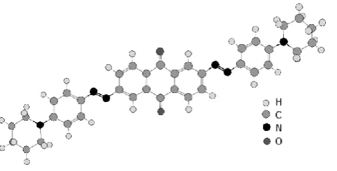
interesting alternative to MR doped systems. 18 The 2,5 azo-substituted anthraquinone (ASAQ)
dye DC161 is dichroic and has maximum absorption at 527 nm. The dye structure is shown on
Fig.1. The dye had been synthesised at Standard Telecommunications Labs, Harlow, UK by Dr.
Coates.
The mechanism of the optical nonlinearity has been shown to be due to the trans-cis
transition in dye molecules in the bulk. 19 We have reported efficiency for these devices to be up
to 1.5% (phase retardation /12) at 80 lp/mm. 20 Based on the trans-cis model, the only limiting
resolution factor is diffusion of cis dye species from illuminated regions into dark regions and a
corresponding diffusion of trans species from dark into illuminated regions.
Devices and measurement techniques
Samples
For the described studies we have chosen planar aligned devices filled with cyano-biphenyl
devices had thickness 5, 9 and 15 microns and used 5CB nematic liquid crystal from Merck as
host material and SiOx as alignment layer. Similar planar aligned devices with E7 host from
Merck (a mixture of cyano-biphenyls) and polyimide as alignment layer have been built to study
the resolution and efficiency behaviour in thick devices. The thicknesses of those are 10 m, 14 m, 20 m, 40 m, 60 m and 125 m. Although higher dye concentrations yield higher
efficiency, 5 we have chosen dye concentration of 0.5% wt in order to decrease absorption and
thus ensure better distribution of writing beam intensity in the highly absorbing media.
Experimental techniques
A holographic grating is recorded on the sample using two Ar+ laser beams (=514 nm). No
external electric field is applied. The beam from the laser is collimated and expanded to obtain a
uniform intensity profile. Then it is split by a non-polarising beam splitter. In order to make
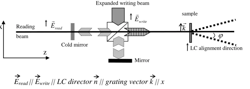
measurements at high spatial resolution, a Michelson interferometer setup is used (Fig.2).
The beams are directed to overlap on the sample. The interference pattern that is formed is a
sinusoidal grating. This setup allows large angles between the interfering beams without
increasing the path difference between them. Therefore the path difference stays within the
coherence length of the laser. The recorded spatial frequency in this setup can be varied from
2.5 m to 33.3 m (400 lp/mm to 30 lp/mm).
A weak He-Ne laser beam (=633 nm, 1 mW) is used to read the recorded grating. The
diffracted orders are symmetrical. The first diffracted order is measured using a photo-multiplier and oscilloscope during switch “on” and switch “off” of the writing beams. All the beams are
polarised along the director of the LC, i.e. along the alignment direction of the device. In order to
minimize the error due to fluctuations, the measurement was done by collecting and averaging a
Experimental results
Resolution
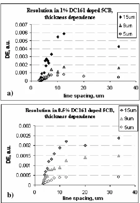
From the resolution studies in DC161 (Fig.3) we find that the efficiency remains the same when a
larger spatial frequency (10-33 m) is used, and starts to decrease when the spacing becomes
smaller than 8-10 m. It almost vanishes for grating periods smaller than 2.5 m (400 lp/mm).
Such uniform behavior of the efficiency for grating periods larger than 8-10 m is very
important for device applications. An arbitrary image will contain a range of spatial frequencies,
and the efficiency should remain the same for all these spatial frequencies in order to ensure a
faithful image transfer. Moreover, the limiting resolution is virtually independent of the dye
concentration and the sample thickness.
Thick devices
From previous research, we know that efficiency strongly increases with an increase in the
sample thickness. 20 Therefore, a simple way of improving efficiency of DC161 doped devices
could be to build thick devices. This should not lead to a loss in resolution. To test this hypothesis
experiments in thick 0.5% DC161 doped E7 devices (40, 60 and 125 m) have been conducted in
the Raman-Nath regime. In the following experiment low efficiency is due to the fact that we are
using low doping level, different host material and alignment agent; also, as confirmed by
microscope studies, the dispersion of the dye is not homogenous.
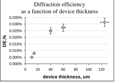
Measurements in thick devices show that:
the efficiency grows with device thickness but, due to the strong absorption making
only the front part of the device active, it starts to saturate if the thickness is increased
above 40m. (Fig. 4.);
diffraction efficiency in a 0.1% doped 125 m thick device showed low diffraction
efficiency, about 4 times lower than in 0.5% doped device of the same thickness and
material (the efficiency scales with the dye concentration at low doping levels).
Equally high resolution and almost unchanged temporal switching characteristics 21 compared
with thin (≤25m) devices make thick devices based on DC161 doped liquid crystals a good
option for improving the efficiency.
The diffraction regime defines the maximum possible diffraction efficiency obtained from
the grating. At small induced retardation (<1 rad) and consequently low diffraction efficiency
(<20%) Bragg matched and Raman-Nath diffraction regimes do not differ significantly (Fig. 5.).
Only when the induced retardation approaches at least /2, the difference in these two regimes
becomes significant. In order to achieve a uniform light intensity distribution throughout the
whole thickness of the device, low dye concentrations (0.1% wt) should also be used.
Conclusions
Diffraction efficiency is approximately independent of line spacing in all devices doped with an
azo-substituted anthraquinone dye for gratings with a period larger than 8-10 m. This resolution
threshold is independent of the device thickness, and dye concentration within the 0.5% wt - 1%
The diffraction efficiencies observed in 0.5% doped E7 devices are low, of the order of
0.02% - 0.03% and correspond to optical phase excursion of about /30. In 1% doped 5CB
devices diffraction efficiency reaches 1.5% (optical phase excursion /12). 20
Experiments on thick devices have confirmed that the resolution is independent of the
sample thickness. The dynamics in 125 m thick devices is almost the same as in thin ones (≤ 25 m). The efficiency of the thin devices increases when the thickness is increased. At a given
optical intensity of writing beams, in samples thicker than 40 m diffraction efficiency saturates,
probably due to the high absorption in the devices.
We had shown earlier 20, that diffraction efficiency of the discussed system is
proportional to dye concentration and increases quadratically with device thickness. Therefore for
device optimisation it is better to increase thickness and choose dye concentration accordingly.
Acknowledgements
The authors are grateful to Dr. D Coates for fabricating dyes. We would like to thank Gates
Cambridge Trust for financial support of Dr. O. Trushkevych and EPSRC Platform Grant GR/S12074/01 “Liquid crystal Photonics: Photonics of molecular Materials” for financial support
of Dr. N. Collings.
References
1. I. Jánossy and L. Szabados, “Optical reorientation of nematic liquid crystals in presence of photoisomerisation”, Phys. Rev. E. 58, 4, pp.4598-4604 (1994);
3. L. Marrucci, D. Paparo, M. R. Vetrano, M. Colicchio, and E. Santamato, G. Viscardi, “Role of dye structure in photoinduced reorientation of dye-doped liquid crystals” Journal of Chem. Phys., 113, 22, pp.10361-10366 (2000);
4. I. C. Khoo, “Dye-doped photorefractive liquid crystals for dynamic and storage
holographic grating formation and spatial light modulation”, Proc. Of the IEEE, 87, 11, pp. 1897-1911 (1999);
5. O.Ruzak, N.Collings, W.A. Crossland, T.D. Wilkinson, A.B. Davey and I.C. Khoo, “Dynamic holographic gratings in methyl red-doped nematic liquid crystals”, Journal of N. Opt. Phys. And Mat., 12, 4, pp. 441-447 (2003);
6. F. Simoni, L. Lucchetti, D. Lucchetta, and O.Francescangeli, “On the origin of the huge nonlinear response of dye-doped liquid crystals”, Opt. Express 9, pp. 85-90 (2001);
7. http://www.hamamatsu.com;
8. G. Moddel, L. Wang, “Resolution limits from charge transport in optically addressed spatial light modulators”, Journalof Applied Physics, 78, 12, pp. 6923-6935 (1995);
9. S. Mias, N. Collings, T.D. Wilkinson and W.A. Crossland, “Technology and performance of A-Si:H OASLMs”, Recent Res. Devel. Optics, 3, pp. 125-144 (2003);
10.N.A. Clark and S.T. Lagerwall, “Submicrosecond bistable electro-optic switching in liquid crystals”, Appl. Phys. Lett. 36, pp. 899-901 (1980)
11.D Williams, S G Latham, C M J Powles, M A Powell, R C Chittick, A P Sparks and N Collings, “An amorphous silicon/chiral spatial light modulator”, J. Phys. D: Appl. Phys. 21, pp. s156-s159 (1988).
12.F.A. Perennes, W.A. Crossland, “Optimization of ferroelectric liquid crystal optically addressed spatial light modulator performance”, Optical Engineering, 36, (8), pp. 2294-2301 (1997).
13.D.V. Wick, T. Martinez, M.V. Wood, J.M. Wilkes, M.T. Gruneisen, V.A. Berenberg, M.V. Vasil’ev, A.P. Onokhov and L.A. Beresnev, “Deformed-helix ferroelectric liquid-crystal spatial light modulator that demonstrates high diffraction efficiency and 370-line pairs/mm resolution”, Appl. Opt., 38, 17, pp. 3798-3803 (1999)
15.I.C. Khoo, A. Diaz, J. Ding, K. Chen & Y. Zhang, “Collective and Individual Molecular Nonlinear Photonics of Liquid Crystals”, Journal of N. Opt. Phys. And Mat., 12, 2, 277-289 (2003);
16.L. Lucchetti and F. Simoni, Y. Reznikov, “Fast optical recording in dye-doped liquid crystals” Optics Lett., 24, 15, pp.1062-1064 (1999)
17.J. Parka, “Photorefractivity of the dye-doped NLC layers and possibility of their application” Opto-electronics review 10, 1, pp.83-87 (2002)
18.O. Ruzak, N. Collings, W.A. Crossland, T.D. Wilkinson, A.B. Davey“New Highly Effective Dopant For Liquid Crystals As Materials For Optically Addressed Spatial Light Modulators.”, Proc. SPIE Int. Soc. Opt. Eng. 5518, pp.104-114 (2004).
19.O. Trushkevych, N.Collings, W.A. Crossland, T.D. Wilkinson, A.B. Davey “Optical studies of non-linear behaviour of dye-doped liquid crystal systems”, Mol. Cryst. Liq. Cryst,434, pp. 63/[391] - 77/[405] (2005);
20.O. Trushkevych, N.Collings, W.A. Crossland, T.D. Wilkinson “Optical Nonlinearity In Azo-Anthraquinone Dye Doped Liquid Crystals”, accepted for publication in Journal of
Nonlinear Optics Materials;
List of figures
Fig. 1. The structure of 2,5 azo-substituted anthraquinone (ASAQ) dye DC161.
Fig. 2. Experimental setup for holographic grating formation experiment.
: a), c)
dye concentration as parameter b), d) sample thickness as parameter.
Fig. 4. Efficiency in thick devices: saturation with thickness. The experiment is in the
Raman-Nath regime, spatial frequency 12.5 m, =514 nm, optical power 50 mW/cm2. The samples are
0.5% wt DC161 doped E7.
Fig. 2. Experimental setup for holographic grating formation experiment. Diffraction is in xz plane.
Eread || Ewrite || LC director n || grating vector k || x
x
z
k
write
E
Expanded writing beam
sample
LC alignment direction read
E
Reading
beam
Cold mirror
Mirror
Fig. 3. Diffraction efficiency (in arbitrary units) versus the period of the grating ( in m): for 1% wt (a) and 0.5% wt (b) dye concentrations; sample thickness as parameter.
a)
Fig. 4. Efficiency in thick devices: saturation with thickness. The experiment is in the Raman-Nath regime, spatial frequency 12.5 m, =514 nm, optical power 50 mW/cm2. The samples are 0.5% wt DC161 doped E7.
Efficiency as a function of device thickness
0.000% 0.005% 0.010% 0.015% 0.020% 0.025% 0.030% 0.035%
0 20 40 60 80 100 120
device thickness, um
D
E
,%
Fig. 5. Diffraction efficiency in Raman-Nath and Bragg regimes.