ISSN Online: 2327-4379 ISSN Print: 2327-4352
DOI: 10.4236/jamp.2017.59138 Sep. 15, 2017 1658 Journal of Applied Mathematics and Physics
Forging Optimization and Microstructural
Simulation of an Inconel 718 Alloy Used in
Turbine Discs
Seyyed Hashem Mousavi Anijdan
*, Mehrdad Aghaie-Khafri, Vahid Joshaghani
Faculty of Materials Science and Engineering, K. N. Toosi University of Technology, Tehran, IranAbstract
Simulating microstructure evolution during forging of superalloys is of great interest for manufacturer of critical components, particularly in aerospace ap-plications. In this research, a phenomenological approach using a mathemati-cal model was employed into a commercial finite element code, i.e. Abaqus, to study recrystallization and grain growth of IN718 supperalloys during forging. Model validation was performed by compression testing. Results show that the measured recrystallized volume fraction and the grain size were in good agreement with the model predictions. Subsequently, the model was used to simulate the evolution of microstructure in a turbine disc. Finally, a technique based on Tagushi method was used to determine the influence of forging pa-rameters such as forging temperature, ingot height to diameter ratio, and top die velocity on the resultant microstructure. Uniform and refined micro-structure of final forging was considered into the objective function. Opti-mum as well as the poorest parameters combination was attained through
S N analysis. As well the contribution of each parameter on microstructure development was determined through variance analysis.
Keywords
Forging, Turbine Disc, Inconel 718 Alloy. Tagushi, ANOVA Analysis, Microstructure
1. Introduction
A turbine extracts energy from a hot gas flow to drive the compressor and the accessory gearbox. As inlet gas temperature of the gas turbine engine increases, How to cite this paper: Anijdan, S.H.M.,
Aghaie-Khafri, M. and Joshaghani, V. (2017) Forging Optimization and Micro-structural Simulation of an Inconel 718 Alloy Used in Turbine Discs. Journal of Applied Mathematics and Physics, 5, 1658-1667.
https://doi.org/10.4236/jamp.2017.59138
DOI: 10.4236/jamp.2017.59138 1659 Journal of Applied Mathematics and Physics its efficiency gets better. Therefore, the parts used in the turbine require to be made from superalloys which can operate in high temperature and high pressure with superior efficiency.
The turbine disc, as the object of this study is the rotating part which supports the turbine blades. During operation, gas turbine discs operate under severe conditions, such as high stress combined with centrifugal force and thermal gra-dient. These severe working environments require a proper forging of the disc to be performed. Grain size control in the forging of the Inconel 718 superalloy is a very important issue because the grain size is closely related to the mechanical properties and the performance of the discs [1] [2]. Na et al. [3] studied the evo-lution of the microstructure in the process of two-step blade forging of 718 alloy using a 3D FE simulator that contained a microstructure module. Also, Medei-ros et al. [4] characterized the hot deformation behavior of IN718 alloy and ob-tained a relationship between the microstructure evolution and the processing map using compression testing. Zhang et al. [5] developed microstructure evolu-tion model and studied the effect of forging parameters on the microstructure based on the processing maps in disc forging of 718 alloy. As well, in terms of optimization efforts, He et al. [6] used Tagushi method to optimize the micro-structure in cylinder upsetting. In the present study a micromicro-structure evolution model was implemented into a commercial finite element, i.e. Abaqus. A robust technique based on Tagushi method was presented to determine the influence of forging parameters on the microstructure evolution and to obtain the optimum combination of forging parameters in turbine disc forging.
2. Method
The objective of this study was to investigate the influence of forging parameters on the microstructure uniformity and smallness in to improve mechanical properties of heavy forgings. To achieve these goals the following steps were taken into account. First, the microstructure objective function was defined and the forging parameters were defined. Then, an appropriate orthogonal array was constructed. After the above steps, proper constitutive equations and micro-structural models were implemented into Abaqus simulation software and finite element simulations were performed based on the arrangement of orthogonal array. Additionally, the results of the simulations were transferred into the Ta-gushi signal-to-noise (S/N) ratio. By doing this an optimum and poorest combi-nations of forging parameters were obtained. Finally, variance analysis (ANOVA) was performed to determine the significance of each parameter under investigation.
3. Constitutive Equation
DOI: 10.4236/jamp.2017.59138 1660 Journal of Applied Mathematics and Physics
( )
0
ˆ 1 ln( pl) (1 ) n
pl m
A B C
ε
σ
ε
θ
ε
= + + − (1)where σ is the yield stress, εpl is the equivalent plastic strain, εpl is the equivalent plastic strain rate, A B C n m, , , , ,ε0 are the material parameters measured at or below the transition temperature, and θˆ is nondimensional temperature defined as:
transition
transition transition transition
0 for
ˆ ( ) ( ) for
1 for
melt melt
melt θ θ
θ θ θ θ θ θ θ θ
θ θ < = − − ≤ ≤ >
(2)
where
θ
is the current temperature, θtransition is the transition temperature de-fined as the one at or below which there is no temperature dependence on the expression of the yield stress. θtransition was considered equal to room tempera-ture. The material parameters of the Johsnon-Cook plasticity model for Inconel 718 alloy are listed in Table 1.4. Microstructural Model
From the true stress vs. true strain curves, obtained under various strain rates and temperatures, one can deduce the variation of hardening rate with strain. Also, the critical strain
( )
εc for the onset of dynamic recrystallization can be [image:3.595.206.539.482.530.2]obtained from the inflection point in the curves. The detailed approach is ex-plained elsewhere [7]. The critical strain was about 0.8 times the peak strain, which corresponds to the peak stress in the plot of the true strain vs. true strain. The critical strain is expressed as a function of initial grain size
( )
d0 and Zen-er-Holloman parameter( )
Z in Table 2. Generally, dynamic recrystallizationTable 1. Johsnon-Cook plasticity model parameters of Inconel 718.
variable ε0 A B C n m
unit 1/s Mpa Mpa
value 0.001 450 1700 0.017 0.65 1.3
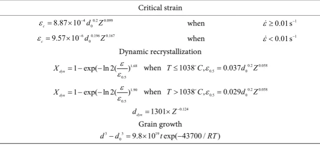
Table 2. Mathematical models for the microstructure evolution during forging of Inconel 718 alloy.
Critical strain
4 0.2 0.099 0
8.87 10
c d Z
ε = × −
when ε≥0.01s−1
6 0.196 0.167 0
9.57 10
c d Z
ε = × −
when ε<0.01s−1
Dynamic recrystallization
1.68 0.5
1 exp( ln 2( )
dyn
X = − − εε when 0.2 0.058
0.5 0
1038 , 0.037
T≤ Cε = d Z
1.90 0.5
1 exp( ln 2( )
dyn
X = − − εε when 0.2 0.058
0.5 0
1038 , 0.029
T> Cε = d Z
0.124
1301 dyn
d = ×Z−
Grain growth
3 3 19
0 9.8 10 exp( 43700 / )
[image:3.595.209.536.575.723.2]DOI: 10.4236/jamp.2017.59138 1661 Journal of Applied Mathematics and Physics occurs near grain boundaries forming a necklace microstructure. This is shown in Figure 1. The variation of the volume fraction of dynamically recrystallized grains
( )
Xdyn versus strain was fitted to an Avrami-type equation. Dynamically recrystallized grain size( )
ddyn was then expressed as a function of Zen-er-Holloman parameter as suggested by Shen et al. [8].Dynamic recrystallization results show different behavior below and above 1038˚C which is the dissolution temperature of
δ
phase. This phase acts as an obstacle against boundary movement.5. Verification of Microstructure Model
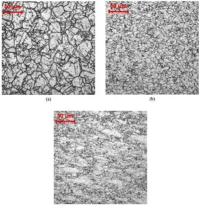
[image:4.595.242.505.371.476.2]To verify the above theoretical microstructure models, the simulation results using FEM, combined with microstructure models were compared with the ex-perimental results in the literature [3]. H. Zhang et al. [3] conducted a non-isothermal upsetting experiment on a cylindrical specimen of 718 alloy with a diameter of 8 mm and a height of 12 mm. 50 percent reduction in height was applied. The de-formation temperature of the workpiece was 1000˚C. The die temperature was 300˚C and the initial grain size was 32 µm. The grain size simulation results (Figure 2) were in good agreement with the measurements of the grain size in different zones of workpiece (Figure 3).
Figure 1. Dynamic recrystallization occurring near given boundary after compression tests at: (a) 954˚C, 5s−1 (b) 1066˚C, 5s−1 [1].
DOI: 10.4236/jamp.2017.59138 1662 Journal of Applied Mathematics and Physics To validate the microstructure models, upsetting of 718 alloy specimen was simulated with Abaqus using the same conditions as mentioned above. Figure 4 shows the result of the grain size simulations which is in good agreement with the results of H. Zhang et al. [5].
In both Figure 2 and Figure 4 three deformation zones can be identified. Dead zone A, easy deformation zone B and free deformation zone C. During deformation, because of the effect of heat exchange and the friction with the die, the top and the bottom of the workpiece are the dead zones. For the material lo-cated in these zones, dynamic recrystallization hardly takes place, as shown in Figure 3(a). As well, as dynamic recrystallization completes, a uniform and fine microstructure is obtained in the easy deformation zone B (Figure 3(b)). In the
Figure 3. Optical microstructure in different zones of the workpiece: (a) dead zone A; (b) easy deformation zone B; (c) free deformation zone C [5].
[image:5.595.233.516.250.538.2]DOI: 10.4236/jamp.2017.59138 1663 Journal of Applied Mathematics and Physics free deformation zone C, there is a duplex grain microstructure for the incom-plete dynamic recrystallization (Figure 3(c)).
The difference between the deformed shapes and the grain size in upsetting simulation and reference [5] could be due to the use of different constitutive eq-uations, friction factors and strain rate in these situations.
6. Objective Function Definition
Microstructure changes, specially grain size variations, are very important to the material behavior. Theoretically, the best situation is to obtain a fine, uniform grain size, and large recrystallized volume fraction in the microstructure. In this study, the mean grain size in each finite element was introduced in which not only the recrystallized grain size and recrystallization extent were considered, but also the grain size in no recrystallization part were evaluated as well. The objective was to minimize the variance of mean grain size in all elements and the average of mean grain size in the final product, which is expressed as [9]:
(
)
22 1 1 ( ) N i
m ave i
i
ave des NE
i i
D D dV
M D D
dV β = = − =
∑∫
+ −∑∫
(3)where
N
is the total number of elements, i mD is the calculated grain size for every element, β is the weight factor, Ddes is the desired mean grain size and
ave
D is the average of mean grain size in the final product, which is expressed
as: 1 1 N i m i i ave N i i D dV D dV = = =
∑ ∫
∑ ∫
(4)7. Design Variables Selection and Orthogonal Array
Construction
The volume of ingot was taken as a constant. Ingot height to diameter ratio
H D, forging temperature T and compression speed v where chosen as de-sign variables. Uniform and small microstructure of the final forging part was considered the objective function. Ingot height to diameter ratio was 2 - 3, the initial forging temperature was in the range of 400˚C - 600˚C, and the top die velocity was 3 - 9 m/s. As shown in Table 3, each parameter had three levels.
8. Simulations
DOI: 10.4236/jamp.2017.59138 1664 Journal of Applied Mathematics and Physics Table 3. Factors and different levels considered for the simulations.
Level H D/ ratio T (˚C) v (m/s)
1 2 3 2 2.5 3 400 500 600 3 6 9
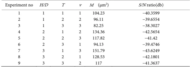
Table 4. Simulation results obtained from Abaqus.
Experiment no H/D T v M (µm2) S/N ratio(db)
1 2 3 4 5 6 7 8 9 1 1 1 2 2 2 3 3 3 1 2 3 1 2 3 1 2 3 1 2 3 2 3 1 3 1 2 104.23 96.11 82.25 134.36 117.82 94.13 151.79 128.53 117 −40.3599 −39.6554 −38.3027 −42.5654 −41.42 −39.4746 −43.6249 −42.1801 −41.3637
die and the workpiece was neglected. Moreover, inelastic heat fraction of 0.9 was selected to consider the effect of heat generation on the temperature rise during deformation.
Microstructure simulation was performed by implementing Table 2 equations into Abaqus. An initial grain size of 32 µm was assumed to be uniformly distri-buted in the workpiece.
9.
(
S N
)
Analysis
The signal-to-noise
(
S N)
ratio was adopted to analyze the test results in the Tagushi method. The S N function is defined as follows:10log( )
S N= − MSD (5)
where
MSD
is the mean square derivation for the quality characteristics under one trial condition. Usually, there are three categories for quality characteristic. They are: the lower-the-better, the-higher-the-better and the nominal-the better. Regardless of the category of the quality characteristic, a greater S N ratio corresponds to a better quality characteristic.The objective function in this work was M which shows grain size and their scattering from an average size. Ideally, both of them needed to be minimized, hence M was a the-lower-the-better quality characteristic. The mean square derivation for the-lower-the-better quality characteristic was given by:
2 1 1 n i i MSD y n =
=
∑
(6)Where yi is the value of the-lower-the-better quality characteristic and n is the number of the tests for a trial condition.
[image:7.595.204.539.173.291.2]DOI: 10.4236/jamp.2017.59138 1665 Journal of Applied Mathematics and Physics average S N ratio of the microstructure objective function value for each pa-rameter in levels 1 - 3 are shown in Table 5.
Considering average S N ratios and taking into account the fact that higher
S N ratio is better, the optimum and the poorest combination of forge para-meters are shown in Table 6.
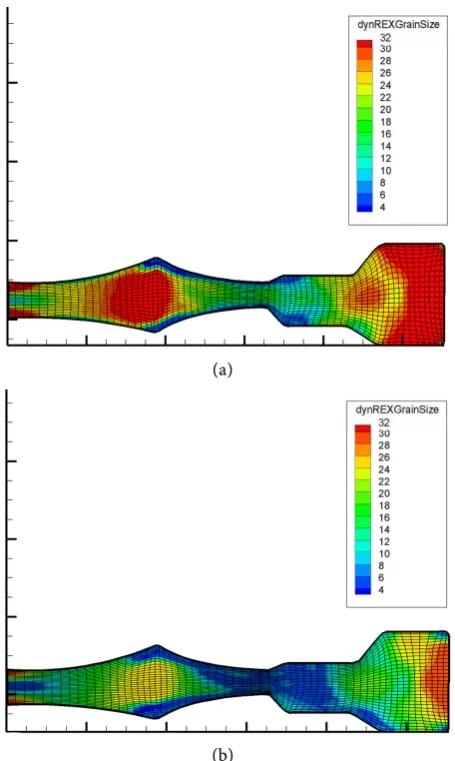
Final grain size simulation was run with the optimum and the poorest forge combinations. Results are shown in Figure 5(a) and Figure 5(b). As can be seen in these figures, the red areas in Figure 5(a), which represents unrecrystallized regions, are nearly gone in Figure 5(b). As a result the uniformity is better in Figure 5(b).
10. ANOVA Analysis
Variance analysis (ANOVA) was performed, to quantitatively investigate the ef-fect of the process parameters. The overall average S N ratio is expressed as:
(
)
(
)
1 1 k
i i
S N S N
k =
=
∑
(7)where k is the number of the tests in the orthogonal array, and
(
S N)
i is theS N ratio of the
i
th test. The sum of the squares due to the variation from theoverall average S N ratio is:
(
)
(
)
21
k
i i
SS S N S N
=
=
∑
− (8)And the sum of the squares due to the variation from the average S N ratio for the ith factor is:
(
)
(
)
21
l
i j ij
j
SS T S N S N
=
=
∑
× − (9)where l is the number of the factor levels (l = 3 in this study), Tj is the
num-ber of the tests of the ith factor at the jth level. The percentage contribution on the
[image:8.595.206.539.552.613.2]ith factor is given by
Table 5. Average S N ratio for each parameter in levels 1 - 3.
Level H D/ T v
1 2 3
−39.43 −41.15 −42.38
−42.18 −41.08 −39.71
[image:8.595.206.541.646.714.2]−40.67 −41.19 −41.11
Table 6. The optimum and the poorest forge parameters combinations.
Optimum level poorest level /
H D 1 3
T 3 1
DOI: 10.4236/jamp.2017.59138 1666 Journal of Applied Mathematics and Physics
( )
% i 100i SS
P
SS
= × (10)
ANOVA results are shown in Table 7. The results show a strong effect of the height to diameter ratio, and forging temperature, as well as a small effect of the die speed.
11. Conclusions
In this study, mathematical models were used to predict the microstructure evo-lution during forging of a superalloy used in turbine disc after the results were validated by compression testing. A robust process based on Tagushi method was used to determine the optimum combination of forging parameters (height
(a)
(b)
Figure 4. Grain size simulation for 718 alloy used in turbine disc (a) with the poorest forge parameters combination (b) with the optimum forge parameters combination.
Table 7. Variance Analysis for S N ratio.
/
H D T v
[image:9.595.261.489.244.625.2]DOI: 10.4236/jamp.2017.59138 1667 Journal of Applied Mathematics and Physics to diameter of the ingot, forging temperature and velocity of the top die) and the poorest combination of forging parameters. This was done to obtain a fine and uniform grain size. Two simulations were run based on the above combinations. Simulations results showed more uniform microstructure with more recrystal-lized volume fraction in forging with an optimum combination of parameters compared with the forging with the poorest combination of parameters. Also, ANOVA analysis was used to quantitatively investigate the effect of each forging parameter on the microstructure. These later results showed a strong effect of height to diameter of the ingot, and the forging temperature compared with the top die velocity.
References
[1] Azarbarmas, M., Aghaie-Khafri, M., Cabrera, J.M. and Calvo, J. (2016) Microstruc-tural Evolution and Constitutive Equations of Inconel 718 Alloy under Quasi-Static and Quasi-Dynamic Conditions. Materials & Design, 94, 28-38.
https://doi.org/10.1016/j.matdes.2015.12.157
[2] Azarbarmas, M., Aghaie-Khafri, M., Cabrera, J.M. and Calvo, J. (2016) Dynamic Recrystallization Mechanisms and Twining Evolution during Hotdeformation of Inconel 718. Materials Science and Engineering A, 678, 137-152.
https://doi.org/10.1016/j.msea.2016.09.100
[3] Na, Y.-S., et al. (2003) Simulation of Microstructures for Alloy 718 Blade Forging Using 3D FEM Simulator. Journal of Materials Processing Technology, 141, 337-342. https://doi.org/10.1016/S0924-0136(03)00285-1
[4] Medeiros, S., et al. (2000) Microstructural Modeling of Metadynamic Recrystalliza-tion in Hot Working of IN 718 Superalloy. Materials Science and Engineering: A, 293, 198-207. https://doi.org/10.1016/S0921-5093(00)01053-4
[5] Zhang, H., et al. (2010) Hot Die Forging Process Optimization of Superalloy IN718 Turbine Disc Using Processing Map and Finite Element Method. Proceedings of the Institution of Mechanical Engineers, Part B: Journal of Engineering Manufacture, 224, 103-110. https://doi.org/10.1243/09544054JEM1571
[6] He, X., Yu, Z. andLai, X. (2009) Robust Parameters Control Methodology of Micro-structure for Heavy Forgings Based on Taguchi Method. Materials & Design, 30, 2084-2089. https://doi.org/10.1016/j.matdes.2008.08.039
[7] Park, N., et al. (1997) Two Step Forging of Alloy 718. Superalloy, 718, 625-706. https://doi.org/10.7449/1997/Superalloys_1997_173_182
[8] Shen, G., Semiatin, S. and Shivpuri, R. (1995) Modeling Microstructural Develop-ment during the Forging of Waspaloy. Metallurgical and Materials Transactions A, 26, 1795-1803. https://doi.org/10.1007/BF02670767
Submit or recommend next manuscript to SCIRP and we will provide best service for you:
Accepting pre-submission inquiries through Email, Facebook, LinkedIn, Twitter, etc. A wide selection of journals (inclusive of 9 subjects, more than 200 journals)
Providing 24-hour high-quality service User-friendly online submission system Fair and swift peer-review system
Efficient typesetting and proofreading procedure
Display of the result of downloads and visits, as well as the number of cited articles Maximum dissemination of your research work
![Figure 1. Dynamic recrystallization occurring near given boundary after compression tests at: (a) 954˚C, 5s−1 (b) 1066˚C, 5s−1 [1]](https://thumb-us.123doks.com/thumbv2/123dok_us/174627.512003/4.595.242.505.371.476/figure-dynamic-recrystallization-occurring-given-boundary-compression-tests.webp)