Vibration Control of Flexible Base Mobile
Manipulators under Impedance Controller Using
New Control Element on the End Effector
M. Salehi , G. R. Vossoughi
Abstract — In this paper new method for vibration control of Flexible Base Mobile Manipulator (FBMM) under constrained motion control were proposed. When robotic manipulator with base flexibility contacts environment under impedance control, vibration occurs at transient and contact moments. Vibration causes position and force inaccuracy, instability and servicing requirements of equipment. Previous active vibration control is based on vibration control elements on the base of manipulator. As new method, control element on the manipulator’s End Effector was proposed for vibration control and vibration damping on the mechanism. This controller includes same or better response and lower control coefficients because of its performance on the End Effector instead of the base.
Active Vibration Controller on the End Effector (AVEE) was simulated for two models. First model is a simple FBMM composed of a 2 DOFs planar manipulator and a single DOF moving base with flexibility in between. Second model is an advanced 10 DOF’s FBMM. Combined Impedance/AVEE controller provides desired position/force control with satisfactory damped vibration especially at the point of contact. Results show that control coefficients of active vibration controller on the Base (AVCB) are so bigger than these coefficients for AVEE.
Index Terms — Mobile Manipulator, Vibration Control, Position/Force Control, Flexible base , End Effector
I. INTRODUCTION
xpanding the effective workspace is excellent specification of mobile manipulators. Moving base mobile manipulators such as macro/micro manipulators, space manipulators and underwater robotic vehicles can be used in finishing, repair and maintenance, inspection, welding, cleaning, and machining operations. Also, base of mobile robot is flexible and assumption of base rigidity is unreal. Flexibility and compliance of the base in most cases results in the loss of accuracy and limitations in achievable speeds. The source for base flexibility can be for example the suspension system and/or the internal structural flexibility of the base platform or joint/link flexibility associated with a supporting manipulator/crane in a macro/micro type manipulator arrangement.
As we know, all previous researches concentrated on the
vibration active control method on the manipulator’s base. Hootsmans and Dubowsky considered the macro/micro manipulator and large mobile manipulator for joint motion controlling and decreasing the structural vibration in 1992. [1] Torres and Dubowsky proposed a simple damping algorithm for flexible base manipulator in 1996, but active feedback control on the base wasn’t included. [2] Mavroidis and Dubowsky continued their researches and they proposed Inferred End-Point control for long reach manipulator with base vibration. [3]
Also, the pioneering work in stiffness /impedance control is by Salisbury and Hogen [4,5]. Kazerooni presented a frequency domain interpretation and design method, and proposed an implementation more suitable for use with industrial robots [6]. The problem of impedance control and dynamic stability of mobile manipulators (without flexibility) has been addressed by Inoue [7]. The concept of virtual / generalized impedance was proposed by Lao and Donath to avoid obstacles by redundant manipulators [8]. Modeling and impedance control of a two- manipulators system handling a flexible beam was addressed by Yan and Lin [9]. Multiple impedance control of cooperative manipulator in space was proposed by Mossavian, Papadaouplos and Poulakakis as an approach for handling large cargo in space [10]. To reduce contact forces in a mobile manipulators, simple damping-based posture control has been proposed by Kang and his colleagues [11]. Flexibility and active vibration control hasn’t been considered in above investigations.
Jaydeep used adaptive coefficients for force control law and he achieved better response using this control law [12]. A research group at DLR Aerospace Research Centre have studied impedance control of light link manipulators with fixed base and joint flexibility. They proposed a new approach based on decoupled dynamics of torque and position errors [13,16]. Impedance control of rigid mobile manipulator was studied by Tan and his colleagues [14] and experimental results were presented with a mobile PUMA 560. Hang proposed a fuzzy control law for impedance control and was able to achieve a better response when impedance parameters were selected based on fuzzy rule base [15]. Vossoughi and Karimzadeh addressed the general impedance control of a flexible link manipulator using singular perturbation method and they presented simulation results of impedance control for a 2 DOF manipulator with fixed base [17].
A simple and high performance active vibration control hasn’t been proposed under impedance control in all above researches for accurate position/force response. Of Course, Active vibration actuator on the manipulator’s base has been
E
__________
M. Salehi is a Ph.D. student at Sharif University of Technology in Iran. Research fields are Robotics, Control and Mechatronics., [email protected]
selected for vibration damping, but active vibration control element on the End Effector proposed as first time with smaller control coefficients and same or better response. In this paper, a general dynamic model is considered for mobile manipulators with base flexibility. A new formulation for the impedance control based on Sliding Mode control theory (SMIC) is then addressed for achieving the desired impedance. Also, new active vibration control element on the End Effector (AVEE) is proposed. Better specification of combined SMIC/AVEE is simulated for a simple Flexible Base Moving Manipulator (FBMM), composed of a 2 DOF's planar manipulator mounted on a flexible 1 DOF base. Also, this controller is simulated for an advanced 10DOF’s model. The better performance of the proposed controller during impact moments of manipulator’s end Effector and the environment is also simulated.
II. GENERAL DYNAMIC MODEL
Nonlinear dynamic model of flexible base mobile manipulator was considered here as;
( ) ( , ) ( ) ( )
( , )
M X X C X X X K X X G X H u ur r
τ = + + +
+
&& & & &
T x
x y
X =[ , 1, 2,...,θ1,θ2,...] T F
F1, 2,...,1, 2,...] ,
0
[ τ τ
τ = (1)
Where, y is base flexibility vector, x1 ,x2, … are base
movements in Cartesian coordinates, θ1,θ2,...are angular movements of manipulator links, F1 , F2, … are applied
force to base and τ1,τ2,... are applies torque to links. M, C, K, G, H represent inertial matrix, damping and centrifugal and Coriolis_terms matrix, stiffness matrix, gravity matrix and matrix of input road of base or so on.
If, we assume that mobile manipulator doesn’t include any base flexibility and input roads, the slow dynamics of mobile manipulator will be derived as following relation:
( ) ( , ) ( )
slow M X X C X X X G X
τ = &&+ & & +
(2)
III. IMPEDANCE CONTROL
Impedance relation indicates desired impedance by matrices Mm,Bm,Km,Kf :
( ) ( )
( ) ( )
M em B e K em m K ef f
e x t xd t
ef F t F td
+ + = − = − = − && & (3) f K m K m B m
M , , , are impedance positive definite
matrices and x d , Fd are desired position and force vectors. Now, we consider combined sliding surface as following form:
1 2 c
sc = +e F e F Z& + (4) So, following relation indicates compensating dynamics for combined sliding surface:
1 2 3
Z&c =AZc +K e K e K e+ &+ f (5)
, ,
1 2 3
K K K are compensating positive matrices.
It must be considereds=s&=0 for reaching to desired sliding mode:
1( )
2 1
1( )
2 1
Zc F e F e
Zc F e F e
−
= − +
−
= − +
& && &
&
(6)
We will have following relation by substituting equation (6) into equation (5);
1
( 1 2 2 2 2). ( 2 1
1 ).
2 2 1 2 3
e F F AF F K e F K
F AF F e F K ef
− + − + + − − − = − && & (7) 3 , 2 ,
1 K K
K are specified by comparison between two
relations (7) and (3) as desired impedance relations;
2
1 1 1
1 2 2 1
1 1 1
2 2 1 2
1 1
3 2
F
K F Mm Km AF F
K F Mm Bm F AF
K F Mm Kf
− − − = + − − − = − + − − = (8)
Sliding mode law was defined as following relation:
( ) . ( ) . 0t
s&c = −F sc = −k sat sc −αsc − ∫β s dtc (9) Where
α
,
β
,
k
are positive definite and diagonal matrices. Function sat is as below:( ) / 1
( )
/ / 1
sign sc sc
sat sc s s
c c φ φ φ > = ≤
⎧
⎨
⎩
(10)Chattering coefficient,φ, is a positive definite vector for decreasing the changes of sliding surface variable.
Now, we propose sliding mode impedance control. We specify tracking error and then we will calculate desired acceleration vector of FBMM.
( ). e x x d
e J x d
e J J x d
= −
⇒ = Θ Θ −
⇒ = Θ + Θ −
& & &
& && && &&
(11)
Using sliding mode control law, desired acceleration vector
is as following relation:
( ) . ( ) . 1 2
( ( ). ) ( )
1 2
1( )
( )
2 2 1 1 2 2 2 3
( )
s F s k sat s s e F e F Z
J J xd F J xd F Z F s
X J Ls J
Ls F AZ F K e F F K e F K ef xd F s
α
= − = − − = + +
⇒ Θ + Θ − + Θ Θ − + = −
−
⇒ Θ = = − + Θ
→ = + + + +
− +
& & && &
& && && & & & && && & &
& &&
(12)
J is corresponding Jacobian Matrix of FBMM. Control torque/force vector indicates as following relation by substituting equation (12) into motion equation (2):
1 ( 1 )
MJ Ls C MJ J G
τΘ = − − + − − & &Θ +
(13)
IV. ACTIVE VIBRATION CONTROL
ON THE BASE (AVCB)
vibration domain increases at the contact point and especially, vibration damping actuators is so necessary in these moments. Therefore, active combined vibration, position & force controllers are proposed for achieving to desired position and force accurately. Following relation is considered for Active Vibration Control of the manipulator’s base (AVCB). Control forces could be applied by Hydro-electrical or Electro-mechanical elements.
b y bP K b y bD K b y bI K b
F =− && − & − (14)
b F
,
b
y are control forces and vibration vector to the suspension points of the base. KbI,KbD,KbPare vectors of PID or PI coefficients.
V. ACTIVE VIBRATION CONTROL ON THE END EFFECTOR (AVEE)
Control law is as following relation, related to vibration vectors of End Effector point. As a new method for active vibration control of robot at the contact moments, we use control element on the manipulator’s End Effector.
Fe = −KeI ey&& −KeD ey& −KeP ey (15)
e F
,
e
y are control forces and vibration vector on the suspension points of the End Effector.
eP K eD K eI
K , , are
vectors of PID or PI coefficients of control element on the End Effector.
This control force is applied between End Effector and environment by AVEE. It is added to contact force at impact and contact moments by this feedback controller. We will show that the values of control coefficients for this control method are so smaller than the value of control coefficients of AVCB. Therefore, it is better and one point controller on the End Effector. Also, Simulation results show that AVEE provides better desired damping rate and stability guarantee at impact and contact moments.
Relations (8) show the solution existence of SMIC. So, combined position/force surface converge using these control coefficients and stability of proposed impedance sliding method guarantees. Also, proposed AVEE is a feedback PID controller and it is stable by using suitable control coefficients. Therefore, stability of whole dynamics guarantees under proposed SMIC/AVEE.
VI. SIMULATION RESULTSAND COMPARSION
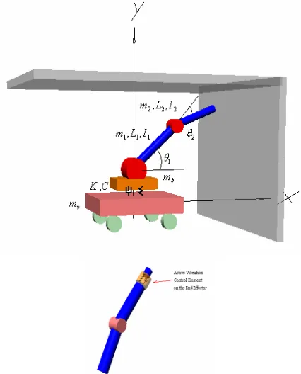
First, a FBMM model is considered with 2 DOF’s manipulator and single DOF base with flexibility in between. Model has been shown in Figure 1.
FBMM model specifications:
mv=5 kg ; mb=2.5 kg ; m1=1 kg ; m2=1 kg ; L1=0.5 m ;
L2=0.5 m ; I1=0.125 kg.m2 ; I2=0.125 kg.m2 ; k=2000 N/m ;
c=100 N.sec/m , g=9.81 m/sec2
Desired path is the motion of FBMM in direction x. End Effector of manipulator contacts the wall with stiffness coefficient K=1000 N/m in direction y. Then, End Effector
moves on the wall surface. Desired position and force on the wall are yd =x2d = 0.8 m and Fd = 2.25 N. This is same
application as painting, cleaning or welding.
Two cases were simulated by AVCB (Case 1) and AVEE (Case 2). Left column of following figures shows simulation results of case 1. Case 2 is indicated in right column. These simulation results indicate that desired position/contact force (Figures 2, 3 and 4, 5) were provided completely. Contact force on the wall surface is 2.5 N and y coordinate of the base was provided by both tow controllers. Active control forces of the base and End Effector are shown in Figures 8, 10. Maximum value and time of control force for case 2 is less than these values for Case 1. Maximum active force is about 1.71 N and control time is about 1.6 to 2.5 sec for AVCB. But these parameters are 1.52 N and 1.6 to 1.75 sec for better vibration response by AVEE.
New proposed impedance control model, SMIC provides desired position and force for two cases. But, combined SMIC/AVEE causes better response and damping effects using composed active vibration controller on the End Effector (Figure 6, 7, vibration for two cases). Figures 5 and 9 shows that vibration of the base and contact force were damped before 1.8 sec with same domain by AVEE. But, they were damped before 2.3 sec by AVCB (Figures 4 , 6).
[image:3.595.320.533.432.696.2]Accurate study proves that all dynamic and control parameters including state variables and control torques/forces have same or better response by new impedance/vibration control method, SMIC/ AVEE especially at contact points. Therefore, new combined controller causes better response for achieving to desired path and force. Other interesting result is lower value for feedback control coefficients of AVEE. It is simple and will be provided chipper, with lower effect of noise.
Case 1: SMIC/AVCB; Active Vibration Control of Mobile Manipulator on the base
( =8, =80, =8
bP K bD
K bI
K )
Case 2: SMIC/AVEE; Electro-mechanical Element as
Active Vibration Control of Mobile Manipulator on the End Effector ( =0.6, =7, =1
eP K eD K eI
K )
Fig. 2. y coordinate of End Effector Fig 3: y coordinate of End Effector
Fig 4: Contact Force between End Effector and roof Fig 5: Contact Force between End Effector and roof
Fig 6: Vibration of Central mass of the base Fig 7: Vibration of Central mass of the base
Fig 8: Control Force on the Central Mass of Base Fig 9: Control Force of Actuator on the End Effector
Fig 10: Control Torque of Link 1 Fig 11: Control Torque of Link 1
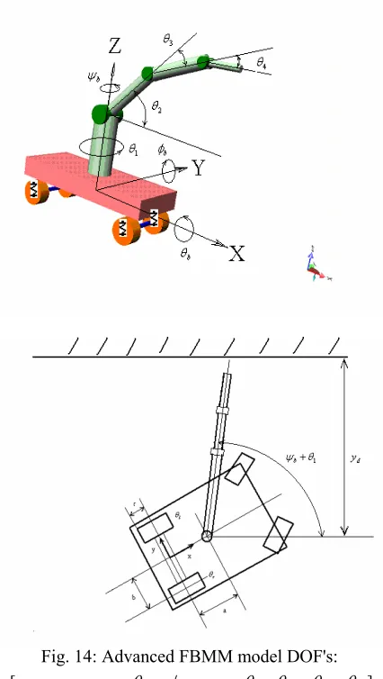
Fig. 14: Advanced FBMM model DOF's:
[xb yb zb θb φb ψb θ1 θ2 θ3 θ4]
A) Advanced FBMM specifications:
20
b
m = kg,a=1 m,b=0.5 m
5 , 5 , 3 , 2
1 2 3 4
m = kg m = kg m = kg m = kg
2 , 2 , 1.5 , 1
1 2 3 4
L = m L = m L = m L = m
2 2 2
1.67 . , 6.67 . , 8.3 .
Ibx = kg m Iby = kg m Ibz = kg m
2 2 2
1 2 3
2 4
1.67 . , 1.67 . , 0.56 . ,
0.17 .
L L L
L
I kg m I kg m I kg m
I kg m
= = =
=
(16)
B) Initial conditions
[ 1 2 3 4 ( 0)]
0 0 0 0 0 0 0
3 9 9
xb yb zb θb ϕb ψb θ θ θ θ t
π π π
= =
=⎡⎢ ⎤⎥
⎣ ⎦
(17)
C) Equivalent Stiffness of suspension system or tyres
( ) 1 2
K zb =K zb +K
K1=1000 N m/ 2, K2 =10000 N m/
(18)
D ) Desired Position and Force
Desired path is the motion of FBMM for contact process. Then End Effecter of manipulator included AVEE will contact the wall. Desired End Effecter trajectory on the wall is a circular path (R=0.5 m) as rapid finishing process. Desired y position and force on the wall were selected as yd
=2 m and Fdy = 2.5 N. In this simulation, friction force was
[image:5.595.56.269.63.440.2]considered, because the process is a medium contact.
This friction was simulated by friction coefficient on the tangential direction on the circular path.
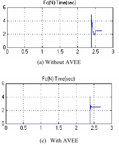
Figure 15 shows vibration of central mass with and without AVEE and Figure 16 shows contact force. Figure 17 shows 3D motion of End Effector. We see accurately that vibration and contact force damped better with lower time and domain by AVEE under constrained motion control.(after contact) In other word, structural mass of base and robotic manipulator was deleted by AVEE and vibration damped accurately in the point of its source, impact to the wall. Therefore, control coefficients of this new control element on the End Effector are must be lower clearly. Also ,damping coefficients for vibration control on the base must be selected greater values.
(a) Without AVEE
(b) With AVEE
[image:5.595.317.530.378.675.2](a) Without AVEE
[image:6.595.43.275.23.512.2](c) With AVEE
Fig. 16: Contact Force
Fig. 17: 3D motion of End Effector By SMIC/AVEE
VII. CONCLUSION
Mobile manipulator applications are many and varied and will be expanded more and more. Of course, manipulator’s base is flexible for this kind of manipulator and it isn’t negligible. Flexibility and suspension effect cause vibration. Compliance of the base in most cases results in the loss of accuracy and limitations in achievable speeds. New active vibration control method on the End Effector (AVEE) was proposed under sliding mode impedance control for Flexible Base Mobile Manipulator (FBMM).
This proposed controller was simulated for two models First model is a simple flexible base mobile manipulator composed of 2 DOFs planar manipulator and a single DOF moving base with flexibility in between. Second model is an advanced 10 DOF’s FBMM. Simulation results show better damping response for desired position and force by
combined AVEE and new Sliding Mode Impedance Control (SMIC) comparing with Active Vibration Control on the manipulator’s base (AVCB). Interesting result is lower value for feedback control coefficients of AVEE. Therefore combined SMIC/AVEE will be provided same or better desired impedance (position and force) and better damping effect at the contact point. Also, it is small controller with damping effect accurately in contact point. It is chipper with lowest effect of noise. This is the first time that this new impedance/vibration control method is proposed for FBMM.
REFERENCES
[1] N. Hootsmans , S. Dubowsky , "Large Motion Control of an Experimental Mobile Manipulator with limited sensing", Proceedings of the 31st SICE Annual Conference ,1992, pp. 983-986.
[2] M.A. Torres, S. Dubowsky and A. Pisoni, "Path planning for elastically-mounted space manipulators", IEEE Int. conf. Robotics and Automation, San Diego, CA, May 1994.
[3] Mavroidis, Dubowsky and Raju , " End point control of Long reach manipulator systems", The International Journal of Robotics , 1991, pp. 1836-1842
[4] Salisbury, J. Kenneth (Stanford Univ.), "Active Stiffness Control of a Manipulator in Cartesian Coordinates", Proceedings of the IEEE Conference on Decision and Control, v 1, 1980,pp. 95-100
[5] Hogen. N, "Impedance Control An Approach to Manipulation: Part I,Part II, Part III", ASME J.Dynamic Syst. Measurement. Contr. Vol. 107, No. 3, 1987, pp.1-24
[6] Kazerooni. H. Sheridan. T. B. and Houpt P. K., "Robust compliant motion for manipulators, Part 1: Fundamental concept of compliant motion: Part II: Design method", IEEE. Journal. Robotics and Automation, Vol 2, No. 2 , 1986, pp 83-105.
[7] K. Inoue, T. Miyamoto, Y. Okawa, " Impedance Control of Mobile Manipulator with the stability to Extended force", Pro. IROS , IEEE, 1996 , pp. 721-728.
[8] Ch. Lao, M. Donath , " Generalized Impedance Control of a redundant Manipulator for handling tasks with position uncertainty while avoiding obstacles", Proc. of the 1997 IEEE, Int Conf. on Robotics and Automation, New Mexico, 1997, pp. 575-579.
[9] D. Yan, Y. Lin , " Modeling and Impedance Control of a Two- manipulator system Handling a Flexible Beam" , Proc. of the IEEE, Int. Conf. on Robotics and Automation , New Mexico, 1997.
[10] Mossavian, Papadaouplos , "On the control of space free–flyers using multiple impedance control", Proc. of IEEE on Robotics and Automation , April 21-27, 1997.
[11] Kang, Komoriya, koutoku and Tanie," Reduced internal effect in damping-based posture control on mobile manipulator", Proc. of the 2001 IEEE/RSJ in Intelligent Robots and systems, Hawaii, USA, 2001. [12] Jaydeep Roy, L. Whitcomb , " Adaptive Force Control of position/velocity controlled robots, Theory and Experiment", IEEE Transactions on Robotics and Automation, Vol. 18, No 2, April 2002, [13] A. Schaffer, C. Ott, U. Frese, G. Hirzinger , " Cartesian impedance control techniques for torque controlled light-weight robots ", Proc. IEEE Int. Conf. on Robotics and Automation ,2002. pp 657-663
[14] J. Tan, N. Xi and Y. Wang, "Integrated Task Planning and Control for Mobile Manipulator", Int. Journal of Robotics Research, Vol. 22, No 5, May 2003, pp. 337-354,
[15] L. Hang, S.S. Ge, Th. Lee , " Fuzzy unidirectional force control of constrained robotic manipulators", Journal of Fuzzy Set and Systems, No 134, 2003, pp. 135-146
[16] Ch. Ott, A. Shaffer, A. Kugi , "Decoupling Based Cartesian Impedance Control of flexible joint robots", Proc. 2003, IEEE Int. Conf. on Robotics and Automation, DLR, German Aerospace Center, 2003. , pp. 2666-2672
[17] G. R. Vossoughi and A. Karimzadeh ," Impedance control of a two degree-of-freedom planar flexible link manipulator using singular perturbation theory", Journal of Robotica, Cambridge University Press, April 29, No 24, 2005, pp. 221-228
[image:6.595.56.263.52.304.2]