MR Image Reconstruction from Pseudo-Hex
Lattice Sampling Patterns Using Separable FFT
Jae-Ho Kim, Fred L. Fontaine
Abstract— Common MRI sampling patterns in k -space, such as spiral trajectories, have nonuniform density and do not lie on a rectangular grid. We propose mapping the sampled data to a pseudo-hex lattice, taking advantage of its approximate isotropic nature in k-space and square nature in the recon-structed image space. The group structure of the lat-tice is exploited to implement the Fourier transform computations on the data using a separable FFT al-gorithm, which provides signi…cant computational ef-…ciency. We suggest this method can be generalized to multiresolution lattices, in which the signal is rep-resented in di¤erent regions in k-space with varying sampling densities. The operations on index sets and mapping to separable FFT can be implemented e¢ -ciently in software or custom hardware (e.g., FPGA).
Keywords: magnetic resonance imaging, multidimen-sional signal processing, discrete Fourier transforms
1
Introduction
In magnetic resonance imaging (MRI), data is measured on a …nite set of points ink-space (the spatial frequency domain), usually in two or three dimensions. Normally, the reconstructed image needs to be recovered on a …nite set of points on a uniformly sampled square grid within a prescribed …eld of view (FOV). However, the mea-surements in k-space are usually in a nonuniform pat-tern, with varying sampling densities in di¤erent regions of k-space. The sampling pattern in k-space is usually determined by physical constraints such as the ability to change the excitation magnetic …eld precisely and quickly, as well as by the desire to have a higher sampling density near the origin ofk-space, which generally contains more signi…cant information. In fact, relative to standard re-sults of sampling theory, the region near the origin of
k-space is typically oversampled while the outer regions ofk-space are undersampled.
The image reconstruction process usually involves re-gridding in k-space to a square lattice, and applying standard fast Fourier transform (FFT) techniques [1].
Thanks to Weill Medical College of Cornell University. Manu-script submitted April 16, 2007. The authors are with The Cooper Union for the Advancement of Science and Art, Department of Electrical Engineering, New York, NY 10003 Tel/Fax: 1-212-353-4331/4341 Email: [email protected]
Sometimes these steps are combined, as in the case of the non-uniform FFT (NUFFT) algorithm [2]. Regrid-ding is essentially an interpolation process that can in-volve approximating “ideal” interpolation functions, or can be achieved by solving a constrained (weighted) least-squares problem. The simplest form of regridding is mapping the data at an acquired point ~ki to the
near-est point in a square lattice of a prescribed density; this is called nearest-neighbor regridding. In order to use a square grid that is not excessively dense, more precise interpolation techniques are generally required.
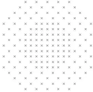
We propose, instead, to resample the data onto what we call a multi-resolution lattice (MRL): points that lie on a base lattice of maximal density, or sublattices (or cosets of sublattices) of the base lattice, for example, as shown in Figure 1. The local sampling density of the MRL re‡ects that of the original measurement process. Once an MRL sampling structure is obtained, a variety of techniques of multirate signal processing can be applied, including optimized decimation and interpolation …lter banks and generalized Cooley-Tukey FFT computations. A key feature of a lattice is that, like a square grid, it has a group structure, which permits a Fourier transform to be de…ned on it. Speci…cally, ifV is a nonsingular ma-trix, the lattice generated by V, denotedLV, is the set
of all points of the form V ~n where ~n is an integer vec-tor. If U is a generator of a sublattice (i.e.,LU LV),
then the elements of the quotient group LV=LU can be
associated with points in LV that lie within a unit cell
for LU, and the “periodicity” that gives rise to a
classi-cal DFT here takes the form of periodicity with respect to the sublattice LU. A …nite Fourier transform can
be de…ned on this group, resulting in points in the tar-get image space on the lattice LU^, where U^ = U 1
T
, within a unit cell for LV^, where V^ = V 1
T
. Note that the sampling density in k-space, jdetVj, and the area (or volume) of the FOV in the target image space,
det ^V , are inversely proportional, as expected; similarly,
By analogy, the ordinary DFT computes the Fourier transform on the quotient group Z=NZ, i.e., the cyclic group with N elements. The DFT is normally applied to the index set f0;1; ; N 1g. Now, identi…cation of subgroups of Z=NZ leads to decimation-in-time and decimation-in-frequency type operations, which are the basis for FFT. In the multidimensional case, when the sampling pattern is square (or, more generally, rectangu-lar), the DFT operation is separable and separable FFT can be applied. The separability leads to computational advantages in addition to the Cooley-Tukey decomposi-tions of the FFT. In the case of the DFT over a lattice quotient group, LV=LU, identi…cation of subgroups also
can give rise to decompositions similar to decimation-in-time and decimation-in-frequency operations. It turns out that the DFT over LV=LU can also be decomposed
in such a way as to be computed, at its core, by a sep-arable FFT operation (this follows from the Smith form decomposition [3] of integer matrices).
When these more general sampling patterns are employed in k-space, many standard signal processing algorithms, such as multirate …ltering (e.g., decimation and interpo-lation) can be applied. One sampling pattern that can provide certain advantages is a hexagonal lattice, which has a more isotropic nature than a rectangular lattice. Consider the task of nearest-neighbor regridding. For the same sampling density, the maximum distance from any point ink-space to a lattice point is about13%less in a hexagonal lattice than in a square lattice, because of the more circular nature of the pattern. However, use of a hexagonal lattice ink-space leads to a hexagonal lattice in the target image space; this in turn would require regrid-ding after image reconstruction to a square lattice, which is normally required for display and other post-processing operations. A pseudo-hex lattice, on the other hand, is a rational lattice that approximates a hexagonal one, and can lead to a rectangular lattice in the target image space.[4] That is,LV, the lattice of support in k-space,
is pseudo-hexagonal, whileLU^, the lattice of support in
the target image space is square.
Our basic proposed image reconstruction process is as follows:
Perform nearest-neighbor regridding from the origi-nal points ink-space to points on a pseudo-hex lat-ticeLV, bounded within a Voronoi cell of a sublattice
LU, which is chosen so that LU^ is square.
[image:2.612.383.477.91.184.2]Perform multirate operations, as necessary, to ac-quire data in a …nal form prepared for Fourier trans-formation. For example, the original lattice can have a high density so that the errors associated with nearest-neighbor regridding are negligible, and then the signal can be downsampled using optimized …l-ters which can be determined in a more systematic way than optimized interpolation functions that are
Figure 1: Points on a multi-resolution pseudo-hex lattice.
designed for original, nonuniform sampling patterns.
Implement the computation of the generalized DFT forLV=LUdata set with a core separable FFT
opera-tion. This requires a remapping of the data, possibly both before and after the separable FFT operation, analogous to bit-reversed addressing that occurs in the one-dimensional case.
In this paper, we present e¢ cient nearest-neighbor algo-rithms, which require minimal computational e¤ort, and demonstrate the mapping of the general form of the DFT considered here to a separable FFT. A sample recon-structed image is shown.
2
Discrete Fourier Transform on
Multi-Resolution Lattices
Although the pseudo-hex lattice described later in this paper is two-dimensional, in this section we will be more general. We associate vectors inRD with D 1 column
matrices;h~x; ~yidenotes the inner product of vectors~x; ~y
in RD; for an invertible matrix A, A^ = A 1 T; and
e( ) = exp ( j2 ). For~x2RD,j~xjdenotes its Euclid-ean length, and for a …nite set S, jSj denotes its cardi-nality. Our signals, corresponding to baseband represen-tations of voltages detected by receiver coils, are complex scalar or vector valued (as arises in the case of multichan-nel MRI).
Given an invertible real matrix V, thelattice generated byV is LV = ~x:x~=V ~n,~n2ZD . We denote an
as-sociated unit cell as UV. The reciprocal lattice isLV^,
and a reciprocal unit cell isUV^. In general,LU LV i¤
U =V M where M is an invertible integer matrix, and LU =LV i¤U=V E whereE is unimodular (an integer
com-prised of the cosets ofLU inLV;jLV=LUj= detV 1U ,
does not depend on choice of generators. From V^ = ^
U MT, we haveL
^
V LU^, and LU^=LV^ =jLV=LUj. An
index set I(U; V)(orI(LU;LV)) is a minimal complete
set of coset representatives of LU in LV (i.e., contains
exactly one point from each coset). Every unit cell UU
of U generates an index set viaI(U; V) =UU\ LV. A
signal gisLV-periodic (orV-periodic) if, for all~kin the
domain of g, g ~k+~ = g ~k for all~ 2 LV. The
set ofLU-periodic signals with support onLV is denoted
P(LU;LV), orP(U; V); every such signal is uniquely
de-termined by its values on any index setI(LU;LV).
If g : LV ! CL is a complex vector valued signal with
support onLV, we de…ne thelexicographic form of g as
gV :ZD !CL given by gV [~n] = g(V ~n). Note that the
lexicographic form depends on the choice of generator matrix. Here, square brackets[ ]denote lexicographic in-dex vectors inZD, and parentheses( )denote “physical”
coordinates inRD. With this structure, we can express
the …nite Fourier transform and inverse transform formu-las associated with the quotient groupLV=LU as:
G(~r) = X
~
k2I(U;V)g ~k e
D
~k; ~rE (1)
g ~k = 1
jI(U; V)j X
~
r2I(V ;^U^)G(~r)e
D
~k; ~rE
Forg2 P(U; V), we haveG2 P V ;^ U^ . We denote the formulas (1) as themultiresolution lattice discrete Fourier transform (MRL-DFT) and inverse transform formulas, respectively. Notice that these formulas do not depend on the choice of generators or index sets (by virtue of the signals’periodicity). The MRL-DFT can be expressed in lexicographic form, with the result that GU^ and gV are
related via the conventional multidimensional DFT [3] with respect to periodicity matrixM =V 1U, as shown
in equation (2) below. Note that the lexicographic for-mulation of the Fourier transform depends on the choice of generator matrices, and in fact the physical structure of the lattice is lost because it forces the base lattices of support in both domains to beZD.
The MRL-DFT equations (1) can be rewritten in lex-icographic form as follows. From U = V M, we have
^
V = ^U MT. With I the identity matrix, we denote I(M; I) = I(M); that is, this is a complete set of in-teger vectors that are distinct modulo M. I MT is
de…ned similarly. Then:
GU^[m~] =
X
~ n2I(M)
gV [~n]e m; M~ 1~n (2)
gV [~n] =
1
jdetMj
X
~ m2I(MT)
GU^[m~]e m; M~ 1~n
Now, every invertible integer matrixM can be expressed
in Smith form as:
M =E1M0E2 (3)
where E1; E2 are unimodular and M0 = diagf 1; ; Dg where i are positive integers. From U =V M, if we takeU0 =U E21 andV0 =V E1, then we have U0 = V0M0. Note that LU0 = LU and
LV0=LV, andM0=M
T
0 Also:
~
m; M01~n =
D
X
i=1 1
i mini (4)
wherefmigDi=1,fnigDi=1, are the components ofm~,~n,
re-spectively. If we take a “natural” choice for I(M0) =
I M0T as I0 = p~2ZD: 0 pi i 1 , then, in
light of (4), the DFT formulas (2) reduce to those of a D-dimensional separable DFT, with respective radixes
1; ; D in each dimension. Thus, a separable FFT
can be applied.
Then what is the di¤erence between the original equation (1) and the ordinary separable multidimensional DFT? We could select as generators U0; V0 at the outset,
al-though as will be discussed later that may not always be possible. The problem is that the choice ofI0 for both
I(M)andI MT corresponds to the index setV0I
0 in k-space, andU0I0in the target image space, and neither
may be the desired set. Speci…cally, they will not be, in general, con…ned to the Voronoi regions for LU andLV^,
respectively. For example, in the 1-D case, the natural index set for an N = 8 point DFT is f0;1; ;7g, but in many cases the centered setf 4; 3; ;2;3gis more desirable. In the multidimensional case, this requires a mapping between each desired index set,I(U; V)and I V ;^ U^ , and I0. It may be di¢ cult to characterize
this mapping in a concise form (i.e., other than a look-up table). However, the procedure we outline in this paper does provide guidance for determining e¢ cient represen-tations of this mapping in many situations.
3
Nearest
Neighbor
Regridding
for
Pseudo-Hex Lattices
We consider MRI data originally sampled on an irregu-lar pattern, speci…cally points that do not lie on a lat-tice and with a sampling density that varies through k -space. There is often a signi…cantly higher density near the origin, and the sampling density in many cases is somewhat isotropic (i.e., does not vary signi…cantly with direction). The …rst step is a nearest neighbor regrid-ding onto a base lattice LV of maximal density. This
on the measure data, with maximum phase error given by max 2 R ~k
max, whereRis the maximum
dis-tance of any point in the FOV in image space from the origin, and ~k
max is the radius of the circumscribing
circle for the Voronoi cell ofLV. Since there are other
distortion e¤ects, such as undersampling and bandlim-ited sampling in k-space (since the object of interest in image space has …nite extent, its actual spectrum in k -space has in…nite extent), and necessarily imperfect in-terpolation and noise, the value max does not have to be prohibitively small. For example, in standard regrid-ding methods, to reconstruct a256 256image,k-space grid sizes from256 256up to1024 1024ares typically used. Here, we employ pseudo-hex grids of comparable sizes.
A generator for a hex lattice is Vhex =
2=p3 1=p3
0 1 . The Voronoi cell is a regular
hexagon, but there is no square sublattice. A pseudo-hex lattice is obtained by using a rational approximation
to Vhex, for example V =
8=7 4=7
0 1 [4]. In this
case, M = p 7 4
0 8 , for p 2 Z
+, yields a generator
U = V M for a square lattice, so that the MRL-DFT generates an image that has support on a square grid. For identical sampling density, ~k
max is about 12.3%
less in the pseudo-hex lattice than in a square lattice.
For an arbitrary point ~k, we want to …nd a nearest lattice point onto which the data can be mapped. In other words, we must …nd an integer vector~n such that
~
e = ~k V ~n has minimum length, j~ej. In general, a search among several indices is necessary. In particu-lar,n^=round V 1~k , where every component ofV 1~k
is rounded to the nearest integer, may not be the cor-rect choice. This is because distance is measured in the physical coordinate space,~k, not the lexicographic space,
~
n. In fact, depending on the choice ofV, the best choice for^nmay not even be rounding each coordinate ofV 1~k
either up or down. The goal is to develop an algorithm that requires searching through a minimal possible set of
^
nvectors, since each test requires computing a distance.
In our approach, by expressing the column vectors inV
in an appropriate orthogonal basis, we can express j~ej2
as:
j~ej2= 64
65( 1 n1)
2
+65 49
1008
65 ( 1 n1) + ( 2 n2)
2
(5) where ~n = n1 n2 T and~ = 1 2
T
=V 1~k. Givenn1, thenn2must be chosen to minimize the second term. We should pick n1 by rounding 1 either up or
down. However, for the pseudo-hex lattice we consider
here, the circumscribing radius of the Voronoi cell, which provides a bound on the maximum value of j~ej, is65=98; therefore, we can reject one of these choices outright if it would cause the …rst term to exceed (the square of) this bound. Thus, we obtain the following simpli…ed nearest neighbor algorithm:
1. Compute~ = 1 2 T =V 1~k.
2. Compute"=j 1 round( 1)j.
3. If" 1 65p65
8 98 0:3316, thenn1=round( 1)and n2 is given by:
n2=round 2 1008
65 ( 1 n1) (6)
4. Otherwise, compute the total error associated with the following two choices: n1 = b 1c, and n2 as above, or n1 = d 1e, and n2 as above. Select the
(n1; n2)pair that minimizesj~ej2.
Note that, since j 1 round( 1)j 0:5, on average we need to perform a comparison between two choices only about 33% of the time; otherwise, the nearest neighbor is computed directly without the need for trial-and-error comparisons.
4
Lexicographic Mapping
Here we discuss the algorithm for mapping the MRL-DFT over the pseudo-hex lattice to a form suitable for application of a separable FFT. The Smith form of the
M matrix given above isM =E1M0E2 where:
E1= 1 0
16 1 , E2= 7 4
2 1 , M0=
1 0 0 56 p
(7) withpis a positive integer determining the overall size of the data set. In standard MRI applications, the target is a 256 256square grid, but sometimes a higher density lattice is used for pre-processing, say1024 1024. With the pseudo-hex lattice, the total number of points needs to be a multiple of56 (as indicated byjdetMj= 56p2). This suggests using 256 224 grid, with p = 32, or
1024 896, withp= 64. Thek-space indices inI(U; V)
are typically scaled so that the coordinates lie in the range
128 ki < 128. Thus, the appropriate U0 matrix
(whose Voronoi cell lies in that region ofk-space) is:
U0= 256 1024
512 1792 (8)
For a256 224 grid, we use:
V0= 8 4=7
and for a higher density1024 896grid we use:
V0= 2 1=7
4 1=4 (10)
The previous section described an e¢ cient nearest neigh-bor regridding algorithm for the …rstV0matrix; a similar
algorithm can be derived for the secondV0 choice. Here we similarly describe a method for generating an index set I(U; V)comprised of points in LV inside a Voronoi
cell of LU, and associating these points with the indices
for the separable DFT associated with M0. Again, for illustration purposes, we consider the casep= 32only.
SinceM0=diagf32;1792g, the core DFT operation is a
32-point DFT in one dimension and 1792-point DFT in the other dimension. The association betweenI(M0), as
required by the separable FFT operation, andI(U; V)is given as follows:
1. I(M0) =f0 p1 31g f0 p2 1791g.
2. ComputeJ =V0I(M0).
3. Ifamodbmeans the integer a0, 0 a0 b 1 such
thatb dividesa a0, then:
a0 = ((a+b=2) modb) b=2 (11)
produces an index in the range b=2 a < b=2. We apply this formula componentwise to the points inJ as follows:
I(U; V) = ((J + 128) mod 256) 128 (12)
The resulting points are in the range 128 ki <
128.
4. The points in I(U; V) lie in LV. The
correspond-ing lexicographic index vectors~n, such that V0~n 2
I(U; V), are computed via:
I0(M0) =V 1I(U; V) (13)
Thus, I0(M
0) is the set of integer vectors that produce
points in the Voronoi cell of U0 when multiplied by V0,
and I(M0) is the set of integer vectors that are used
as indices for the separable FFT operation. A similar process can be used in reverse.
Once the FFT operation is applied, the indices I(M0)
associated with the standard DFT operation must be mapped to an index setI0(M0)such thatU^I0(M0)
cor-responds to an index set ofLU^=LV^ inside a Voronoi cell
of LV^. This Voronoi cell has an approximately
hexago-nal shape. Because V is a rational matrix, this region can be described by a set of linear inequalities with ra-tional coe¢ cients, and thus the mapping of an arbitrary
point ~r 2 LU^ to a point in the Voronoi cell can be
ob-tained by a sequence of integer modulo operations similar to (12). The formulation is a bit more complex because these operations cannot be applied componentwise, and the details are omitted here for brevity. However, it is important to note that a precise formulation can be developed, and it can be realized using …xed-point (i.e., integer) arithmetic. Thus it can be implemented in an ef-…cient manner, both in software and in custom hardware (e.g., FPGA) implementations.
We consider one other situation where we must associate di¤erent sets of lexicographic indices. When we compute the LV=LU MRL-DFT, the set of lexicographic indices
representing points in k-space depends on the choice of generator V, and the lexicographic indices representing points in target image space depends on the choice of generatorU. The physical coordinates in the two spaces do not change, since the Voronoi cells in each domain do not depend on the choice of generator. However, since any two choices for generators are related via a unimod-ular matrix, for example V0 =V E, we can map the
as-sociated lexicographic indices readily through an integer arithmetic operation, namely ifV0~n0 =V ~n, then:
~n0=E~n (14)
5
Results
With the methods described above, an image is recon-structed from a set of 57344 lattice points via separa-ble 32 1792 FFT. The computational complexity of the core FFT operation is32 1792 (log 32 + log 1792), compared with(32 1792)2without a separable FFT ap-proach. The nearest neighbor regridding operation re-quires computing and comparing the results of two pos-sible choices for only about 33% of the points; in other cases, the nearest neighbor lattice point can be computed directly. We also have presented a systematic map-ping between the lexicographic indices corresponding to the standard index set for the lattice (i.e., located in a Voronoi cell) and the indices used by the separable FFT.
In the case of the nearest neighbor regridding, when mul-tiple points map to the same lattice point, their value is averaged. Where the sampling density is more sparse, typically for large ~k, there are lattice points which are not the nearest neighbors to any of the original sample points, in which case the data at these lattice points is taken to be zero.
This result, when applied to data obtained from a phan-tom by a GE Signa 1.5T scanner, is shown in Figure 2.
Figure 2: Reconstructed image.
around a non-rectangular grid. In the next section we discuss how these results can be utilized as the basis for more sophisticated image reconstruction operations to be developed.
6
The Multiresolution Lattice
Frame-work
The proposed strategy is to …rst employ a nearest neigh-bor regridding to a lattice of su¢ cient density that the errors associated with the regridding are negligible com-pared to other e¤ects, such as imprecision in the measure-ment process. In general, the original data is sampled at spatially varying densities. Thus, by applying ap-propriate multirate operations on the dense lattice (e.g., decimation …lters), the signal can be represented in a mul-tiresolution framework.
Suppose the base lattice of maximal sampling density is LV, and the data points are con…ned to the Voronoi cell
associated with a coarse lattice LU LV. The signal,
in general, would be sampled on various sublattices (or their cosets) that lie betweenLU andLV. Thus, a
multi-resolution signal is associated with a structure similar to wavelet packets [5]. This structure allows optimized and ‡exible procedures, such as multirate …ltering and deci-mation and interpolation to alternative lattice structures, as well as generalized Cooley-Tukey FFT computations, to be developed. For example, the passband of a decima-tion or interpoladecima-tion …lter is associated with a certain re-gion in the FOV of the image space, and thus suppression of aliasing and imaging distortions, as well as amplitude and phase distortions, can be achieved in a prescribed region of the FOV [3]. In the regions of k-space that are undersampled, regridding to a lattice with uniform density creates a large number of samples that actually represent the same measurement. By contrast, in our ap-proach, a sparser lattice is employed locally. Alternative methods, for example those which avoid regridding and
instead perform “direct”reconstruction, say from a least-squares approach or based on sophisticated interpolation kernels, are signi…cantly more analytically di¢ cult and therefore are harder to adapt or …ne-tune to particular needs [1], [2].
A key process in reconstructing images from such a multiresolution structure is the ability to compute the DFT for an arbitrary quotient group LV0=LU0, where
LU LU0 LV0 LV. We have outlined a procedure
for e¢ cient mapping of such DFT operations to separa-ble FFTs, speci…cally for the case of a pseudo-hex lattice. In particular, the process of index mapping can be ex-pressed compactly using …xed-point arithmetic, and can be implemented e¢ ciently in software or custom hard-ware (e.g., FPGA) when a look-up table implementation is not practical. Suppose we start with LV=LU where
the generator matrices are chosen so thatU =V M with
M diagonal. If, say, we change the base lattice LV to a
sublatticeLV0 LV (corresponding to decimation), then
the matrix M0 relatingU andV0 viaU =V0M0 may no
longer be diagonal. Thus, working with the MRL frame-work may require changing the generator matrix associ-ated with a particular sublattice, but as indicassoci-ated above, this change of generator can be achieved by integer arith-metic (i.e., multiplication by a unimodular matrix) on the lexicographic index set.
Our particular choice of a pseudo-hex lattice in k-space o¤ers the advantages of direct reconstruction to a rectan-gular grid (avoiding the need for postprocessing regrid-ding), with a hexagonal FOV (avoiding computation of points in the corners of image space, which are often un-necessary in MRI), and with smaller phase errors (caused by the distance ink-space from original measurements to lattice points) than those associated with square grids in
k-space.
References
[1] Sedarat, H., Nishimura, D. G., “On the Optimal-ity of the Gridding Reconstruction Algorithm,”IEEE Trans. Medical Imaging,V19, N2, pp. 306-317, 4/00.
[2] Sha, L., Guo, H. Song, A. W., “An Improved Grid-ding Method for Sprial MRI Using Nonuniform Fast Foruier Transform,”J. Magnetic Resonance, V162, pp. 250-258, 3/03.
[3] Vaidyanathan, P. P., Multirate Systems and Filter Banks, Prentice-Hall, 1993.
[4] Ehrhardt, J. C., “Hexagonal Fast Foruier Transform with Rectangular Output,”IEEE Trans. Sig. Proc.,
V41, N3, pp. 1469-1472, 3/93.