Abstract— The increase of productivity is the major bottleneck in the automotive industries, as well as the constant demand for innovations and new technologies in order to perpetuate its business. In this way, the engineers are always seeking for alternatives to improve their manufacturing processes making them more competitive. However, the increase in productivity must be related not only to the quality of the products but also to the social and environmental issues. The machining area is always launching new cutting tools with new geometries and better tool coatings. This research focus on the investigation of new cutting tools applied on the manufacturing process of safety systems for the automotive industry. The sleeve machining sector of pinion & valve assembly for steering system was investigated to compare the old tools with the new ones with Penta geometry considering the lean manufacturing concept. In 2009 the data showed a percentage increase of 185% for the valve sector productivity. It was verified that the sleeve machining time were reduced providing a 100% of productivity demanded. In addition, despite of the investments in new tools, there was a cost reduction for each sleeve, consequently increasing the annual gain for the installed capacity.
Index Terms — Sleeve, Pinion, Valve, Productivity Increase.
I. INTRODUCTION
The International Institute of Production Research (CIRP) has carried out for a long time researches aiming the understanding of technological performance of machining operations such as tool-life, forces, power, and surface finishing [1]. These researches have a great effect on the industry due to the information related to the selection and design of machine tools, cutting tools, and the optimization of cutting conditions for the machining process, making them more efficient [2]. According to Shaw [3], primary attention has been focused on the modelling of simple geometry orthogonal cutting process involving bi-dimensional plastic deformation.
The orthogonal cutting is the basis of complex mechanisms during the machining process, however when complex cutting tools geometries are used, the basic material
1 Silva, S.P. Federal Universtiy of São João del Rei, Praça Frei Orlando,
170 – Centro – 36.307-352
2 Pereira, R. F. P. Federal Universtiy of São João del Rei, Praça Frei
Orlando, 170 – Centro – 36.307-352
3 Abreu, G. A. Federal Universtiy of São João del Rei, Praça Frei
Orlando, 170 – Centro – 36.307-352
4 Panzera, T. H. Federal Universtiy of São João del Rei, Praça Frei
Orlando, 170 – Centro – 36.307-352
5Brandão, L. C. Federal Universtiy of São João del Rei,Praça Frei
Orlando, 170 – centro – 36.307-352, Brazil (corresponding author phone +55 32 3379 2606, e-mail: [email protected])
removal process is always the same [4].Thus, using specific cutting analysis, the orthogonal cutting process can be easily related to the oblique cutting process. Moreover, the orthogonal cutting is presented in several machining practical situations such as the groove tools used to manufacture specific areas, for example for the assembling of seal rings or elastic rings which are considered difficult to be controlled by cutting operations.
Generally, the machining process optimization for tool-wear/tool-life is associated with economic analysis and process planning [5]. Jawahir et al. [6] affirms that the tool-wear pattern in a worn grooved tool insert is influenced by the three dimensional chip-flow and the complex chip-groove configurations. As showed in a previously experimental study by Fang [7], the progression of tool-wear has a strong correlation with other machining performance measures such as the main cutting force, the consumed power and the chip shape.
Optimization has a strictly relationship with the chip breakability which is affected by the wear tool during the machining process. The tool wear can also be significantly affected by the material flow, mainly when a stable built up edge on the tool is formed [8]. According to Lorentzon and Järvstrat [9] the high stress at the tool–chip interface and the high temperature involved in the machining of steel are considered by several mathematical models to predict the tool wear. Thus, crater wear, as an example, can be the responsible to change the chip shape. In this case, a segmented morphology occurs, generating lower volume of chips which are desired in machining.
Indexes of production are linked to these two-output parameters mentioned before, being important in lean manufacturing philosophy. Nowadays, several concepts of geometry to groove tools with different tribology coatings have been developed to avoid the abrasive wear. The decrease of wear tool is reached by the change of tool geometry providing the increase of the productivity index without increasing costs.
Nowadays, the lean manufacturing exhibits several definitions. According to Womack et al. [10] the best concept is an approach that seeks a better way to organize and manage the relationships of a company and its customers, supply chain, product development and production operations based on the assumption of do more with less (less equipment, less human effort, less time, etc). In addition, according toShah and Ward [11] lean manufacturing approach includes a wide variety of management practices, as just in time, quality systems, cellular manufacturing, among others. Also according to this reference, the basic point of lean manufacturing is that these practices must work
Machining Optimization of Sleeve and Valves
of Hydraulic Steering System
synergistically to create a system that produces high quality products at the pace that the customer wants, without waste.
[image:2.595.377.476.61.151.2]This study was developed in shop floor at TRW company, which is situated in Minas Gerais State in Brazil. Experimental tests were carried out in sleeve flexible manufacturing cell (pinion & valve assembly). The sleeve is responsible to direct the hydraulic oil providing translation movement of the chambers into the hydraulic system Fig. 1. This work investigated a new cutting tool, namely as groove tool, which was developed exclusively to machine multiple grooves.
Figure 1 – Valve (pinion & valve assembly). II. METHODOLOGY
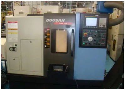
[image:2.595.50.288.196.245.2]This research was focused on Lean Manufacturing philosophy as a support to increase the productivity rate in TRW Steering Systems Company. Thus, a new concept of cutting tools was proposed with the Penta tool Fig. 2. The equipment used was a CNC Lathe Doosan Lynx 220 Fig. 3 with maximum spindle speed of 6,000 rpm and maximum power of 15 kW.
Figure 2 – Penta tool combined
The Penta combined tool was studied to have a better performance considering the values of dimensional and geometric tolerance of the sleeve groove machining. The grooves represent the most critical part of this machining process.
[image:2.595.50.284.391.486.2]It was evaluated new cutting parameters in order to compare with the original parameters of Triangular tool Fig. 4, making it possible to reduce the machining cycle time of sleeve groove increasing the productivity.
Figure 4 – Triangular tool.
The CNC Lathe Doosan was positioned in parallel with another CNC Lathe Doosan Lynx 220 in order to perform the experimental tests. Firstly, it was verified the equipment capability to demonstrate the dimensional stability of the product based on a Gaussian normal distribution, ensuring the quality of machined groove through the MINITAB software. The sample sizes of twenty sleeves were considered significant to carry out the experiments based on the study of capability, according to NBR 5426 and NBR 5429.
Finally, it was evaluated the gains of the sleeve machining in two different conditions. The first condition considered the gains from the average production of 2009 and the second condition was set based on the installed production capacity which was an estimative of the production from March 2010.
III. ANALYSIS OF RESULTS
The first stage of the work aimed optimizing the sleeve machining process modifying the tooling. Table 1 shows the cutting parameters of Triangular tool and Penta tool.
Table 1 – Cutting parameters of Triangular and Penta tool.
Tool Vc1 Feed2 NP3 NE4 Life5 Pr6
Triangular 244 f1 = 0.10 f2 = 0.55 4 3 100 46
Penta 100 0.08 2 5 653 59
1Vc = cutting speed [m/min]; 2feed = feed [mm/rot.]; 3NP = Number of Passes [adm]; 4NE = Number of Edges [adm]; 5
Life = [ Sleeve/edge]; 6Pr = Productivity [sleeves/hours]. The cutting speed (Vc) decreased 59%, see Table 1. The initial feed (f) was set as 0.08 mm/rot. In order to enhance the productivity the machining feed level for the Triangular tool were increased to 0.10 mm/rot to the first and second grooves and 0.55 mm/rot to the third and fourth grooves (see Fig. 5).
According to the manufacture process planning, the Triangular tool machines each groove at a time.
[image:2.595.359.498.626.760.2] [image:2.595.75.275.632.774.2]The machining time of sleeve grooves using the Penta combined tool was 22% lesser than Triangular tool which can be attributed to the step number reduction for two. The Penta combined tool provided simultaneously the machining of the first and third grooves and then the second and forth grooves (see Fig. 6).
Figure 6 - Design concept of simultaneous grooves machining.
According to Table 1 an increase of 1088% in tool life was observed and the increase of productivity rate was overcome due to the use of two CNC lathe. The life end of two cutting tools was defined based on the results of a worn grooved tool pattern, considering that this wear value provides the discard of sleeves. Thus, the groove machining no more attended the dimensional and geometric tolerances specified in the process planning.
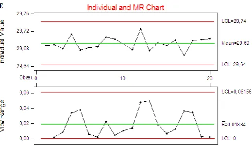
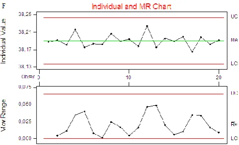
[image:3.595.51.289.134.295.2]In other hand, capability study was carried out using CNC Lathe Doosan, the results can be seen in Fig. 7 (A-F) and Fig. 8 (A-F).
[image:3.595.310.542.223.368.2]Figure 7A – Capability control card of CNC Lathe Doosan – width of first and second grooves
[image:3.595.313.542.418.546.2]Figure 7B – Capability control card of CNC Lathe Doosan – width of third and forth grooves
Figure 7C – Capability control card of CNC Lathe Doosan - Distance from the face of first groove
Figure 7D – Capability control card of CNC Lathe Doosan - Distance from the face of second groove
[image:3.595.49.285.481.630.2] [image:3.595.310.570.591.742.2]Figure 7F – Capability control card of CNC Lathe Doosan - Distance from the face of forth groove.
Figures 8 (A-F) shows the results from the capability control card demonstrating that the variation of measurements during the process was not significant, and it stands into the upper and lower limit controls. According to normal probability plot of Fig. 8 (B-C) it was observed points distributed out of the straight line, which represents the lower limit control to B and the upper limit control to C.
These points demonstrate that a small dispersion among the samples occurred; however the tolerance range specified to the sleeve turning process must be small to maintain the accurate level demanded.
Considering all cases presented in Fig. 8 (A-F), The histograms presented in Fig. 8 (A-F) can be classified as symmetrical, the average value is located into the middle data range with gradual decreasing when set to the extreme sides. In this way, the process can be considered stable, indicating that the characteristic of quality is continuous and there is no restriction on the measured values.
The W Test (Normal Probability Plot) shows that the plotted data approached of a straight line, then the process can be considered normal due to the individual values of dimensional tolerance of sleeve grooves followed a normal distribution.
[image:4.595.63.531.355.489.2]The process dispersion rate (Cp) and the process adjustment and dispersion rate (Cpk) presented superior values than 1.33, which means that the process is statistically under control. Thus, after the implementation of the new machining setup, there was a significant decreasing of 65% in the each sleeve cost, representing an annual real gain of 59% based on the first condition and 62% on the second condition.
[image:4.595.64.529.539.663.2]Figure 8A – Normal distribution of CNC Lathe Doosan capability - A) Width of first and second grooves.
Figure 8C – Normal distribution of CNC Lathe Doosan capability - C) Distance from the face of first groove.
Figure 8D – Normal distribution of CNC Lathe Doosan capability - D) Distance from the face of second groove.
Figure 8E – Normal distribution of CNC Lathe Doosan capability - E) Distance from the face of third groove.
[image:5.595.55.536.416.544.2] [image:5.595.61.536.589.719.2]IV. CONCLUSION
Based on the experimental results the following conclusions can be drawn:
The Penta combined tool allowed to work with small values of cutting parameter, enhancing the tool life; The Penta combined tool contributed to the reduction of machining time, contributing to the increase of productivity capacity;
The cycle time is reduced due to the Penta geometry, which contributes to the fast changing of tooling; The Penta geometry helps to reduce the vibration and cutting forces, resulting in longer tool life;
The two sides of the insert fixing provided not only the higher stiffness, but also the dimensional accuracy in the grooves finishing;
Despite of the large investment in new tooling and equipment, it was possible to reach a cost reduction by the adequate sleeve machining setup, consequently, increasing the annual real gain for the installed capacity.
ACKNOWLEDGMENT
The authors would like to thank FAPEMIG – Fundação de Amparo a Pesquisa do Estado de Minas Gerais and also TRW Steering system company (Lavras – Brazil) for the financial support.
REFERENCES
[1] Wang, J.; Huang, C.Z.; Song, W.G. The effect of tool flank wear on the orthogonal cutting process and its practical implications. Journal of Materials Processing Technology, v. 142, (2003), pp. 338–346.
[2] Kahles; J.F., Machining data requirements for advanced machining systems: CIRP technical report, Ann. CIRP, v. 36, n. (2), (1987). [3] Shaw, M.C., Metal Cutting Principals, 3rd ed., MIT Press,
Cambridge, MA, 2004.
[4] Trent, E.M. Metal Cutting, Butterworths, London, 1977.
[5] Wanigarathne, P.C.; Kardekar; A.D.; Dillon, O.W.; Poulachon, G.; Jawahir, I.S. Progressive tool-wear in machining with coated grooved tools and its correlation with cutting temperature, Wear, v. 259, (2005), pp. 1215–1224.
[6] Jawahir, I.S.; Li, P.X.;Ghosh. R.; Exner, E.L. A new approach for the assessment of comprehensive tool-wear in coated grooved tools, Ann. CIRP, v. 45, n. (1), (1995), pp. 49–54.
[7] Fang, X.D. Experimental investigation of overall machining performance with overall progressive tool-wear at different tool faces, Wear, v. 173, n. (1–2), (1994), pp. 171–178.
[8] Arrazola, P.J.; Arriola, I.; Davies, M.A.; Cooke, A.L.; Dutterer, B.S. The effect of machinability on thermal fields in orthogonal cutting of AISI 4140 steel, CIRP Annals - Manufacturing Technology, v. 57, (2008), pp. 65–68.
[9] Lorentzon, J.; Järvstrat, N. Modelling tool wear in cemented-carbide machining alloy 718, International Journal of Machine Tools & Manufacture, v.48, (2008), pp. 1072– 1080. [10] Womack, J. P.; Jones, D. T.; Roos, D. A máquina que mudou o
mundo. 14. ed. Rio de Janeiro: Campus, 1992, [in portuguese]. [11] Shah, R.; Ward, P. T. Lean manufacturing context, practice
bundles, and performance. Journal of Operations Management, v. 335, p. 1-21, 2002.2, Aug. 1987, pp. 740–741 [Dig. 9th Annu. Conf.