Abstract— The sheet metal formability is a measure of its ability to deform plastically during a forming process. In this paper, the forming limit diagrams of sheet metals are obtained experimentally at both quasi-static (conventional forming) and high strain rate (explosive forming) condition. The selected materials are AISI 1045 steel and an AA6061-T6 aluminum alloy.
The calculation of rate-dependent forming limit diagrams is performed by using the method proposed by authors. The effect of strain rate changes on the forming limits is analyzed. Several yield criteria such as Von Mises isotropic yield function, quadratic and non-quadratic criterion of Hill are used to show the influence of the constitutive law incorporated in the analysis on the rate-dependent forming limits. The effect of the hardening model on the FLD is analyzed by using two hardening laws, namely power law and Johnson-Cook (J-C) law. The comparison between analytical and experimental FLDs shows that J-C model and non-quadratic Hill criteria can be used to obtain the accurate prediction of FLDs at high strain rate condition, rather than power law and other yield criterion.
Index Terms— forming limit diagram (FLD), explosive forming, constitutive equation, yield criteria
I. INTRODUCTION
The prediction of sheet metals formability has become very important in order to decrease the cost of process design. Biaxial stretch-formability is often discussed using the forming limit diagram (FLD). The experimental determination of FLDs is time-consuming and tedious, so that accurate and efficient predictions would be of considerable use.
Over the past several years it has been shown that the formability of metals improves dramatically at high velocities. It led to renewed interest in High Velocity Forming (HVF) techniques, such as explosive forming, electromagnetic forming and electrohydraulic forming.
Perhaps, the earliest report showing that ductility of the dynamically loaded tensile specimens generally increases was published by Wood [1]. This increase in formability observed in high speed forming has been attributed to constitutive behavior, inertial effect and die impact effect. Following this discovery, a systematic experimental and theoretical investigation of velocity effects on ductility has
Manuscript received March 17, 2009.
M. Gerdooei, (PhD Student, Mechanical Engineering Department, Amirkabir University of Technology, Tehran, Iran; [email protected]) B. M. Dariani, (Corresponding author, Associate Professor, Department of Mechanical Engineering, Amirkabir University Of Technology, 424 Hafez Ave., PO Box: 15875-4413, Tehran, Iran; [email protected])
G. H. Liaghat, (Professor, Mechanical Engineering Department ,Tarbiat Modarres University, Tehran, Iran; [email protected])
been carried out. Balanethiram and coworkers [2] performed electrohydraulic forming experiments with 6061-T4 aluminum, oxygen free high conductivity (OFHC) copper and interstitial free (IF) iron, forcing the metals into a conical die at velocity near 150 (m/s). Seth et al. performed forming
of various steel sheets under the impact velocity (50-220 m/s) using high electromagnetic field [3]. They showed that the useful formability of the low-ductility steels could be dramatically improved by high speed forming.
Numerous one-dimensional dynamic large deformation analyses were performed to study the inertial effects in uniaxial tension. Taylor et al. analyzed the effect of inertia on the growth rate of an assumed perturbation in a dynamically stretching, thin stainless steel sheet and showed that many perturbations will be harmless at forming velocities of 100 m/s or greater [4]. Regazzoni et al. used numerical simulation
of dynamic tensile test and showed that at forming velocities above approximately 15 m/s, inertia can induce an additional post-uniform strain (necking) of 5% for rate-insensitive materials, and 10% for rate-sensitive materials [5]. A theoretical analysis of the influence of material inertia on necking in rapidly expanding sheets has been performed by Fressengeas and Molinari using a viscoplastic constitutive relation [6]. Using power law constitutive equation, Gerdooei and Dariani analyzed the dynamic instability of metal sheets under biaxial stretching at strain rate ranging from 0.01/s to 100/s. Their investigation included the combined effects of material constants and strain rate on the critical plane strain [7]. Recently, a new analytical solution of sheet metal instability, at high strain rate forming, developed by Gerdooei and Dariani. This study resulted in the rate-dependent forming limit diagrams at strain rate of 0.01/s to 500/s [8]. The results showed a good comparison between analytical and experimental FLDs for OFHC copper at both quasi static and high strain rate forming. Also, Dariani et al. performed three different experiments in order to investigate formability of sheet metal at quasi-static, intermediate and high strain rate forming. They found some new test procedures to determine the FLDs in the explosive sheet metal forming [9].
In this paper, a theoretical analysis of dynamic instability in the biaxial stretching of non-homogeneous metal sheets is performed. The effects of different material constitutive laws and yield criterion on the FLDs shape and position are investigated at both quasi static and high speed forming. In order to find the best material model, the quasi-static FLDs are achieved by conventional hemispherical punch testing. Also the explosive free forming method is used to obtain the high strain rate FLDs.
II. EXPERIMENTAL PROCEDURE
In this experimental investigation, two different types of experiment were carried out.
Test type 1: Determination of FLDs at quasi-static condition by conventional experimental methods.
Test type 2: Determination of high strain rate FLDs by explosive forming.
In the first type of experiments, the FLDs of sheets were determined using tension tests of notched tensile specimens and stretch forming test with hemispherical punch of 75 mm diameter. The FLD for negative minor strains was determined with notched tensile specimens of various widths, using an Instrone tensile-testing machine. The FLD for plane strain and positive minor strain was determined, using stretch forming tests adopting strips of various widths, and circular and rectangular blanks under various lubricating and non-lubricating conditions. The geometry of notched tensile specimens and stretch forming strips and blank, as well as hemispherical stretch forming die have been given in reference [10]. The tests were performed at a crosshead speed of 5 mm/min and the maximum major strain rate in these series of test were 0.01/s. Printed grid circles of 4 mm diameter on the surface of specimen were used to measure the strain levels in this case. Calculating the major and minor strain of necked point and locating it on the formability diagram the quasi_static FLDs were obtained for both aluminum and steel sheets.
The second type of experiments was designed in order to find the FLDs of sheet at high velocity of explosive forming process. These tests contained stand-off explosive forming of blanks in the cylindrical and flat dies while the blanks were firmly clamped to the die surfaces by holding forces. The specimens formed in the flat die, gave the necking point of left hand side of FLD as well as plane strain region. The cylindrical die was also prepared for explosively deforming of specimens in the positive minor strain state. The explosive charge was powder TNT with density of 0.95. The geometry of specimens as well as explosive forming dies have been given in reference [9].
III. STRAIN RATE-DEPENDENT FORMING LIMIT DIAGRAMS
A. Model description
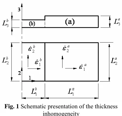
Marciniak and Kuczynski have developed a theory based on the assumption that necking develops from local region of initial inhomogeneity [11]. This inhomogeneity is taken in the form of narrow band of reduced thickness across the sheet (region b, Fig. 1).The inhomogeneity is defined by non-uniformity index:
(1) a
b
L
L
f
3 3
=
Fig. 1 Schematic presentation of the thickness inhomogeneity
where a
L
3and bL
3are thicknesses of homogeneous region
a and non-homogeneous region b respectively. The directions 1, 2 and 3 are considered as the principal direction of stress and strain tensors which are coincidence with each other. The loading over the sheet is performed by applying the constant and determined values of a1
ε
and a 2ε
which are the components of strain rate tensor in the homogeneous region named major and minor strain rate respectively.B. Constitutive equations
The Johnson-Cook and power law constitutive model is taken in to account to describe the flow stress of the material:
(2)
r m
r
M N
T T
T T T
T C
B A
− − =
− + +
= ∗
*
0
) 1 )( ln 1 )( (
ε ε ε
σ
where A,B,C, N and Mare five material constants. The
equivalent plastic strain rate ε is normalized with a reference strain rateε0. Tr is room temperature, and Tmis
melting temperature of the material, and they are constants [12]. Also the power law constitutive model can be written as [13]:
(3)
m
n
k
ε
ε
σ
=
where k, m and n are three material constants.
C. Yield criteria and associated flow rules
Three used yield criteria were Von-Mises, quadratic and non-quadratic Hill models. These criteria and their associated flow rule are described below.
Von-Mises criteria can be written as [13]:
(4)
2
2
3
Y ij ij
S
S
=
σ
Where Sij and
σ
Y denote deviatoric stress components and yield stress, respectively. The associated flow rule can be obtained as[13]:(5)
σ
ε
ij ijε
d
S
2
3
d
P=
where d P
ij
[image:2.595.327.526.48.237.2]
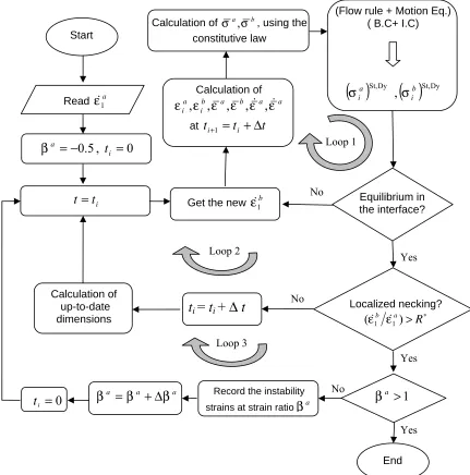
Fig. 2 Numerical procedure of determining the strain rate-dependent FLDs Quadratic Hill criterion can be expressed with respect to
principal stress tensor components as [13]:
(6)
)
1
(
)
(
)
(
)
(
2 2 22
+
−
+
−
+
−
=
R
P
RP
P
R
y z z x x yY
σ
σ
σ
σ
σ
σ
σ
where R and P are constants of Hill criteria. The
associated flow rule can be written as [13]:
(7)
[
]
[
]
[
(
)
(
)
]
)
(
)
(
)
(
)
(
x z y z zz z y x y yy z x y x xxG
F
d
d
F
H
d
d
G
H
d
d
σ
σ
σ
σ
λ
ε
σ
σ
σ
σ
λ
ε
σ
σ
σ
σ
λ
ε
−
+
−
=
−
+
−
=
−
+
−
=
Non-quadratic Hill's yield criterion in plane stress condition is expressed as [13]:
(8) M Y M M
R
R
′ ′′
+
=
−
+
+
+
σ
σ
σ
σ
σ
1 2(
2
1
)
1 22
(
1
)
where R is the average plastic anisotropy ratio and M′ is
Hill's exponent. The associated flow rule can be expressed as [13]: (9) 1 1 1 1 1 2 1 ) 1 2 ( 1 1 ) 1 2 ( 1 − ′ − ′ − ′ − ′ − + + + − + − + =
= M M
M M R R d d α α α α ε ε β
where α is stress ratio.
The heating of the sheet due to the dissipated plastic work can be derived from the equation
(10)
ij ij v
dt
dT
µσ
ε
ρ
C=
where
c
v denotes the specific heat, T the temperature andµ the heat conversion ratio taken equal to unity in case of
an adiabatic heating.
D. Numerical procedure
Based on the method explained in reference [7,8], in order to find the strain-rate-dependent forming limit diagrams, the following numerical stages should be performed step by step:
1- The linear loading path can be determined by constant strain ratio in the homogeneous region (
a a a 1 2 ε ε β = ). 2- An initial value is estimated for the unknown variable b
1
ε
.Equilibrium in the interface?
0
,
5
.
0
=
−
=
i at
β
Read
ε
1aCalculation of
σ
a,
σ
b, using the constitutive law
End Start
Get the new
ε
1b Calculation of a a b a b i ai
ε
ε
ε
ε
ε
ε
,
,
,
,
,
att
i+1=
t
i+
∆
t
No
Yes
i
t
t
=
t
i=
t
i+
∆
t
Localized necking? ∗>
R
a
b
)
(
ε
1ε
1Yes No
a a
a
β
β
β
=
+
∆
β
a>
1
Yes
Calculation of up-to-date dimensions
(Flow rule + Motion Eq.) ( B.C+ I.C)
( )
St,Dy( )
St,Dy,
b i a i
σ
σ
Loop 1 Loop 2 Loop 3Record the instability
strains at strain ratio
β
aNo
0
=
3- The stress and strain analysis in the region a, b is performed after the first small time increment and the magnitude of stress tensors in both region are achieved. 4- The equilibrium condition in the interface is conducted as follows:
(11)
η σ
σ − ≤
=
∆ ∗b b ∗a a l l
F 1 3 1 3
where ∗b 1
σ
and ∗a 1σ
are the longitudinal stress at the end point of region b and start point of region a respectively. Moreover, positive numberη
has a very small value. Ifb 1
ε
has been estimated correctly, the condition (11) will beconfirmed and the program continues from the stage 5. Otherwise the program will return to stage 2 and a new value will be predicted for b
1
ε
.5- According to calculated stress and strain tensor in both regions a and b the sheet dimensions are modified. 6- Instability control in the sheet is performed based on the M-K method. Instability takes place when complete concentration of deformation occurs in region b and the magnitude of b
1
ε increases remarkably. Through attaining
the instability condition, a 1
ε
and a 2ε
values are recorded as major and minor limit strains respectively, and one point of FLD is achieved at known strain path.7- Holding a constant a 1
ε
value and changing a 2ε
value, the new loading path is defined and finally the new analysis is repeated from stage 1. Through step by step changing the strain ratio (β ) from 0.5 to 1, the total forming limit diagram is achieved for special magnitude of major strain rate a1
ε
.The schematic illustration of these stages is shown in Fig.2.
IV. RESULTS AND DISCUSSION
A. Experimental results
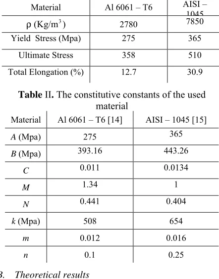
In this study, aluminum alloy Al 6061-T6 and steel AISI-1045 are used. Conventional tensile tests were used to find the yield and ultimate tensile strengths and total percent of elongation for each of the sheets. Both materials were in the form of 1 mm thickness sheet. The mechanical properties of used material are given in table I and II. Note in table I, the total elongation column denotes that the quasi-static ductility of steel sheet is remarkably higher than aluminum sheet.
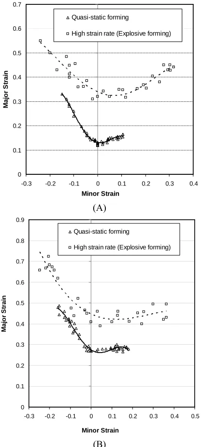
The failure strains and forming limit curves of Al 6061-T6, obtained by mentioned experiments with various strain rates are shown in Fig. 3-A.
As shown in Fig. 3-A, the critical plane strains (FLD0) for quasi-static and high strain rate forming tests are equal to 0.12 and 0.32 respectively. It means that formability is improved 146.1% by explosive forming relative to conventional quasi-static forming. In explosive forming of Al 6061-T6, the formability of sheet can be increased more than two-fold relative to corresponding quasi-static formability. Experimental FLDs were determined for AISI 1045 sheet. The results can be seen in Fig. 3-B. Also, the average increase in formability in explosive free-forming of AISI 1045 is equal to 1.5
respectively. Another important result deduced from comparing the figures 3-A and 3-B is that although there are large differences between quasi-static formability of Al 6061-T6 and AISI 1045 sheet, such is not the case with the high velocity formability of these materials.
Table I. Properties of the used material
Material Al 6061 – T6 AISI – 1045 )
(Kg/m3
ρ 2780 7850
Yield Stress (Mpa) 275 365
Ultimate Stress 358 510
Total Elongation (%) 12.7 30.9
Table II. The constitutive constants of the used material
Material Al 6061 – T6 [14] AISI – 1045 [15]
A (Mpa) 275 365
B (Mpa) 393.16 443.26
C 0.011 0.0134
M 1.34 1
N 0.441 0.404
k (Mpa) 508 654
m 0.012 0.016
n 0.1 0.25
B. Theoretical results
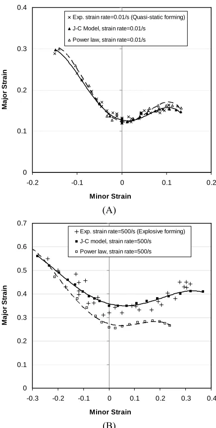
Figure 4 shows the quasi-static FLDs of aluminum and steel sheet achieved by using different yield criteria. It is appear that Von-Mises and quadratic Hill criteria are not able to predict the formability of both aluminum and steel sheets at right hand side of diagram. Thus the non-quadratic Hill criterion is used in the whole analysis. The theoretical quasi-static and high strain rate FLDs obtained by Johnson-Cook and power law constitutive model are compared with experimental result in figures 5-A and 5-B for 5-Al 6061-T6 sheet. The similar results are achieved for AISI 1045 steel sheet, as shown in Fig 6. Figures 5 and 6 shows while both J-C and power law constitutive models give acceptable results at quasi-static forming; the FLD obtained by using J-C model is more accurate at high strain rate condition.
V. CONCLUSION
The aim of this study was to evaluate the formability of 6061-T6 aluminum and AISI 1045 steel sheets under various forming speeds and investigate the effect of different material models. In addition to determining the conventional forming limit curves at quasi-static condition, FLDs were determined in the case of explosive free-forming. More details about experimental and analytical procedures can be seen in references [7-9]. The conclusions are summarized as follows:
[image:4.595.319.540.134.416.2]this huge improvement in formability are inertial stabilization of necks, inertial ironing on impact and changes in constitutive behavior.
0 0.1 0.2 0.3 0.4 0.5 0.6 0.7
-0.3 -0.2 -0.1 0 0.1 0.2 0.3 0.4 Minor Strain
M
a
jo
r
S
tr
a
in
Quasi-static forming
High strain rate (Explosive forming)
(A)
0 0.1 0.2 0.3 0.4 0.5 0.6 0.7 0.8 0.9
-0.3 -0.2 -0.1 0 0.1 0.2 0.3 0.4 0.5
Minor Strain
M
a
jo
r
S
tr
a
in
Quasi-static forming
High strain rate (Explosive forming)
[image:5.595.322.538.100.561.2](B)
Fig. 3 Experimental forming limit diagrams under various strain rates; (A): Al 6061-T6, (B): AISI 1045
- Although the both used material exhibit increase in formability at high velocities, the significant increase is observed for Al 6061-T6, thus in spite of the large differences between quasi-static formability of aluminum and steel sheets, the formability of both materials is almost the same at the case of explosive forming.
- Both J-C and power law models are able to predict the formability of Al 6061-T6 and AISI 1045 sheets at quasi-static forming.
- Prediction of high strain rate FLDs by taking J-C constitutive law into account, gives more acceptable results.
- The most accurate theoretical FLDs are obtained by using the non-quadratic Hill criterion rather than Von-Mises and quadratic criterion.
0 0.1 0.2 0.3
-0.2 -0.1 0 0.1 0.2
Minor Strain
M
a
jo
r
S
tr
a
in
Exp. quasi-static
Theo.Von-Mises
Theo.Quadratic Hill
Theo. Non-quadratic Hill
M = 1.7 at right hand side M = 2.0 at left hand side
(A)
0 0.1 0.2 0.3 0.4 0.5 0.6 0.7
-0.3 -0.2 -0.1 0 0.1 0.2 0.3
Minor Strain
M
a
jo
r
S
tr
a
in
Exp. quasi-static Theo.Von-Mises
Theo.Quadratic Hill Theo. Non-quadratic Hill
M = 1.5 at right hand side M = 2.0 at left hand side
(B)
Fig. 4 Theoretical FLDs of aluminum sheet obtained by different constitutive laws,
[image:5.595.59.266.101.560.2]0 0.1 0.2 0.3 0.4
-0.2 -0.1 0 0.1 0.2
Minor Strain
M
a
jo
r
S
tr
a
in
Exp. strain rate=0.01/s (Quasi-static forming) J-C Model, strain rate=0.01/s
Power law, strain rate=0.01/s
(A)
0 0.1 0.2 0.3 0.4 0.5 0.6 0.7
-0.3 -0.2 -0.1 0 0.1 0.2 0.3 0.4
Minor Strain
M
a
jo
r
S
tr
a
in
Exp. strain rate=500/s (Explosive forming) J-C model, strain rate=500/s
Power law, strain rate=500/s
[image:6.595.50.268.50.482.2](B)
Fig. 5 Theoretical FLDs of aluminum sheet obtained by different constitutive laws
(A):
ε
=
0
.
01
/
s
, (B):ε
=
500
/
s
REFERENCES
[1] W. W. Wood, “Experimental mechanics at velocity extremes - Very high strain rates,” Experimental Mechanics, vol. 7, 1967, pp. 441-446.
[2] V. S. Balanethiram, G. S. Daehn, “Hyperplasticity : increased forming limits at high workpiece velocity,” Scripta Materialia, vol. 30, 1994, pp. 515-520.
[3] M. Seth, V. J. Vohnout and G.S. Daehn, “Formability of steel sheet in high velocity impact,” J. Mech. Phys. Solids, vol. 168, pp. 390 – 400.
[4] J. W. Taylor, F. H. Harlow and A. A. Amsden, “Dynamic plastic instabilities in stretching plates and shells,” J. Appl. Mech, vol. 45, 1978, pp. 105-112.
[5] G. Regazzoni, J. N. Johnson and P. S. Follansbee, “Theoretical study of the dynamic tensile test,” J. Appl. Mech, vol. 53, 1986, pp. 519–528.
[6] C. Fressengeas, and A. Molinari, “Fragmentation of rapidly stretching sheets,” European Journal of Mechanics and Solids, vol.13, 1994, pp. 251- 268.
[7] M. Gerdooei, and B. M. Dariani, “Dynamic analysis instability of sheet metal under biaxial stretching,” Amirkabir Journal of Science & Technology, vol. 18(67-B), 2007, pp. 31-39.
0 0.1 0.2 0.3 0.4 0.5 0.6 0.7
-0.3 -0.2 -0.1 0 0.1 0.2 0.3
Minor Strain
M
a
jo
r
S
tr
a
in
Exp. strain rate=0.01/s (Quasi-static forming)
J-C Model, strain rate=0.01/s
Power law, strain rate=0.01/s
(A)
0 0.1 0.2 0.3 0.4 0.5 0.6 0.7 0.8 0.9 1
-0.4 -0.3 -0.2 -0.1 0 0.1 0.2 0.3 0.4 0.5 Minor Strain
M
a
jo
r
S
tr
a
in
Exp. strain rate=500/s (Explosive forming)
J-C Model, strain rate=500/s
Power law, strain rate=500/s
(B)
Fig. 6 Theoretical FLDs of steel sheet using different constitutive laws,
(A):
ε
=
0
.
01
/
s
, (B):ε
=
500
/
s
[8] M. Gerdooei, and B. M. Dariani, “Strain-rate-dependent forming limit diagrams for sheet metals,” proc Instn Mech. Engrs, Part B: J. Engineering Manufacture, vol. 222(B), 2008, pp 1651-1659. [9] B. M. Dariani, G.H. Liaghat, And M. Gerdooei, “An Experimental
Investigation of Sheet Metal Formability under Various Strain Rates,” proc Instn Mech. Engrs, Part B: J. Engineering Manufacture, Accepted for publication on 5 Feb 2009.
[10] M. Shakeri, A. Sadough, and B. M. Dariani, “Effect of pre-straining and grain size on the limit strains in sheet metal forming,” proc Instn Mech Engrs, vol.214(B), 2000, pp. 821-827.
[11] Z. Marciniak and K. Kuczynski, “Limit strains in process of stretch forming sheet steel,” J.Mech. Phys. Solids, vol.9, 1967, pp. 609-620.
[12] G. K. Johnson and W. H. Cook, “Fracture characteristics of three metals subjected to various strains, strain rates, temperatures and pressures,” Eng. Fracture Mech, vol. 21, 1985, pp. 31–48. [13] W. F. Hosford, R. M. Caddell, Metal Forming Mechanics And
Metallurgy, 2nd, Prentice Hall inc., 1993.
[14] X. Li, “Development of a Predictive Model for Stress Distributions at the Tool-Chip Interface In Machining,” J. Mater. Process. Technol, vol. 63, 1997, pp.169–174.
[image:6.595.344.522.50.462.2]