CONTROL DATA
CORPORATIONCONTROL
DATA®
8092
Te I e Programmer
CONTROL DATA
CORPORATIONCONTROL DATA®
8092
TeleProgrammer
PROGRAMMING REFERENCE MANUAL
Rev.
Date
A
8/24/64
Chanqe 1 5/21/65
Change 2 8/25/66
5/15/67
RECORD OF REVISIONS
Notes
Reprint with revision.
Revised to reflect ECOs 1163, 1198,
1268, 1291, 1334, TITI, T354,
1401,1402. 1403. 1411, 1431, 1470, 1505,
and 1585.
(Revision packet)
Revised to reflect ECO DP2193.
(Revision packet)
Renrint (includes chrlnae
1rlnd 2)
CONTENTS
CHAPTER ONE-PROGRAMMING General Characteristics
The Central Processor
Basic Concepts in Programming the TeleProgrammer Instruction Word Format
8092
Instruction RepertoireDescription and Examples of Instructions Load Instructions
LDN - Load A (No Address Mode) LDM - Load A (Memory)
LD I Load A {Indirect}
LCM - Load Complement to A (Memory) LC I Load Complement to A (Indirect) TTA - Tag Register Contents to A BER - Contents of BER Register to A Store Instructions
STM - Store A (Memory) S T I Store A {Indirect} ATT - A to Tag Register
ABR - A to B~ffer Entrance Register ABX - A to Buffer Exit Register Jump Instructions
ZJP Jump, if Contents of A
=
0 NZP - Jump, if Contents of A:f
0 PJP Jump, if Contents of A ~ 0 NJP Jump ,if Contents of A<
0 UJP Unconditional JumpShift Instructions
SHA - Shift A Left One Bit Arithmetic Instructions
AD N - Add (No Address) ADM - Add (Memory Address) AD I Add (Indirect Address) SBN - Subtract (No Address) SBM - Subtract (Memory Address) SB I Subtract {Indirect Address} RAM - Replace Add (Memory Address) RAO - Replace Add One (Memory Address) Logical Instructions
LP N - Logical Product (No Address) LPM - Logical Product (Memory Address) LP I Logical Product {Indirect Address} LSN - Logical Sum (No Address)
LSM - Logical Sum (Memory Address) LS I Logi~al Sum {Indirect Address}
Input/O utput INN OUT
-I B -I
IBO INA OTN
-Instructions Input Normal Output Normal Initiate Buffer Input Initiate Buffer Output Input to A
Outout No Address Control Instructions
EXF -CIL CBC ERR HLT
External Function
C lear Interrupt Lockout Clear Buffer Controls Error Stop
Halt
CHAPTER TWO = OPERATION TeleProgrammer Operator's Console
Switches Displays
Status Indicators
Starting the 8092 TeleProgrammer Loading A Program or Data
Entering Data From the TeleProgrammer Console Examining the Storage Contents
CHAPTER THREE
1-34
1-34
1-35
1-37
1-38
1-39
1-39
1-40 1-401-42
1-421-43
1-43
2-1
2-22-4
2-5
2-7
2-7
2-7
2-8A BRIEF LOGICAL DESCRIPTION OF THE TELEPROGRAMMER Input/Output Section
Program Step Arithmetic Section Storage Section Control Section
GLOSSARY APPENDIX
Appendix A - TOSAS - A TeleProgrammer Assembler Appendix B - Programming Examples
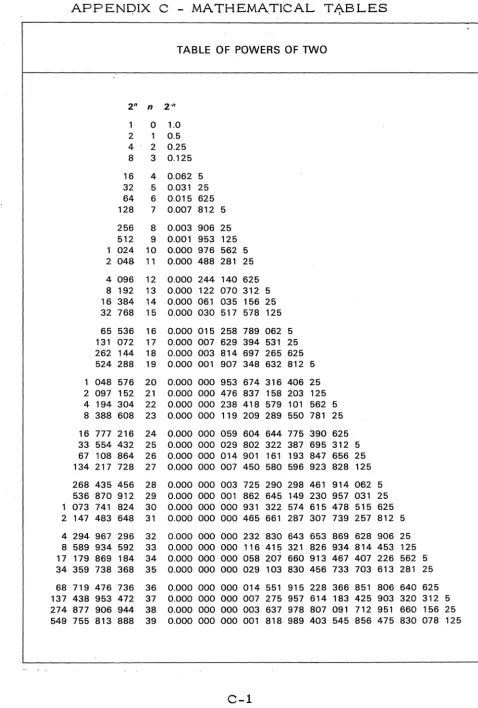
Appendix C - Mathematical Tables
8092 TeleProgrammer
CHAPTER ONE
PROGRAMMING
GENERAL CHARACTERISTICS
The CONTROL DATA~:< 8092 TeleProgrammer IS a highly flexible and
versatile stored program processor specially designed as a high speed
buffer memory system for use in a variety of data communication
appli-cations.
Among the more important features are the following:
stored program
parallel mode of operation 8-bit word length
2048 words of core storage - 4096 (optional) 1 Direct I/O Channel (8 bits)
1 Buffer I/O Channel (8 bits)
versatile instruction repertoire of 42 instructions 3 Auxiliary Tag registers of 4 bits each
indirect and direct addressing and modification interrupts
12 bit external function address codes 7 internal program registers
physical size: height, 68 inches; width, 34 inches; depth, 30 inches
storage reference cycle time of 4 microseconds
The ability to use the OSAS . or OSAS-A assembler for those who have a 160 or 160-A computer.
~:< Registered Trademark of Control Data Corporation
THE CENTRAL PROCESSOR
The TeleProgrammer is a parallel, single address electronic data
processor. Operations are controlled by an internally stored program
located in sequential addresses. The storage cycle time is 4
mlcro-seconds. The basic memory may be expanded from 2048 words to
4096 words. Each internal core word contains 8 bits. Instructions
are executed in one to four storage cycle times; with times varying
from 4 to 16 microseconds. The average instruction time is
approxi-mately 10 microseconds.
The Block Diagram indicates the principal functional divisions
ARITHMETIC
-
CORESTORAGE
t
ICONTROL
i
INPUT/OUTPUTBASIC CONCEPTS IN PROGRAMMING THE TELEPROGRAMMER
The TeIeProgrammer has some Unique features for programming. Most
of these center around the word length of 8 bits. In order to carry
addresses fur 4096 words, 12 bits are required (2 12 = 4096, where
highest address IS 212 - 1). To provide for 12 bits, the
TeleProgram-mer makes use of three 4-bit Tag registers (Tag registers 1, 2, and 3).
The carryover from 8 bits to 4 additional bits, in the Tag register,
causes a split in the second octal digit from the left. This is indicated
below:
4-bit Tag reg. 8-bit word length
3 1 2 3 3
Split octal digit
In this manual, the 8,.;; bit word length will be represented as two full
octal digits and one quartic digit (the leftmost 2 bits). The Tag registers
will be generally represented as shown above, with one full octal digit
(on the left) and a single bit (0 or 1) on the right. The jagged
( c:J
D)
ends of the registers indicate the split octal digit.In addition, this manual will refer to numbers of "three octal digits" being
contained in the 8-bit word length. Actually, this is physically impossible,
since three octal digits occupy 9 bits and there are only 8 bits in the
TeleProgrammer word. However, what IS meant here, is that the
leftmost bit of the three digit octal number IS to be discarded. For
example, show the octal number, 277, in a TeleProgrammer word.
Octal 277 =
a
10 111 111 In binarydiscard)
1
quartic digit2 octal digits
This convention of representing the contents of the 8-bit words will be used
many times in this manual. Looking at the above 9-bit configuration,
one can see that to discard the leftmost bit, it must be zero. This means that the highest quartic digit of the word is 3. This, in turn, indicates
the maximum "octal" of three digits which can be expressed In the 8 .. bit
word length; --it is 377. The octal range 000 through 377 IS equivalent
to 256 registers. Since each Tag register holds 4 bits, there are 16
possible configurations for the 4 bits (0000 through 1111). Thus, 16 times
256
=
4096 total registers available.WORD FORMAT
People who work with computers are generally acquainted with the term,
"octal". It is the number base associated with three bits --which In
turn, provides eight possible number states (zero through seven). Since
the 8092 TeleProgrammer has an 8-bit word length and partitioning by
three bits over the complete word is inefficient; the number base of four
with partitioning by two bits is used for the ~ two bits of the word.
The number base of four, is referred to, in this manual, as QUARTIC.
Keep in mind, that only the ~ two bits of the word length is expressed
in Quartic. The lower SIX bits are expressed by two octal digits. The
upper QUAR TIC digit IS represented by bits, as shown below:
Bits 00
01 10
'lii
The Upper QUAR TIC Digit
o
1 2
3
The CONTROL DATA 8092 TeleProgrammer word contains 8 binary
digits. These are shown below with the least significant bit (bo ) on the
right. Single Word Binary Format
I
8 bitsI
I
b7I
b6I
b5I
b4I
b31b2I
b1I
bOI
Any binary digit above can be represented by any combinations of ones
or zeros. Although the 8092 operates in binary, it is more efficient to
consider the word format as containing 2 octal and 1 Quartic digits, as shown below:
Single Word Format With Two 0 ctals and 0 ne Quartic
1-Z3
Quartic Digit(0,1,2, or '3)
8 bits ~I
c\
~
INSTRUCTION WORD FORMAT
The TeleProgrammer operates on a two word instructional set. Most
instructions are contained in a set of two sequential storage locations.
The first word contains the Function Code, in the lower 2 octal digits,
and the Tag register designator, T, in the upper quartic digit. The
second word of the instructional set holds: an operand of 2 octals and 1
quartic, or a partial address of 2 octals and 1 quartic. Three modes
of operation are possible in the 8092; NO ADDRESS MODE, MEMORY
ADDRESS MODE, and INDIRECT ADDRESS MODE. Examples are
shown below:
NO ADDRESS MODE
Where T = 0, since there is no Auxiliary Tag register used in this mode. The operand must contain 3 digits in the octal range of 000 thru 377.
MEMORY ADDRESS MODE
Where T can equal 0, 1, 2, or 3. The lower 8 bits of the operand address appear in the second word and the upper 4 bits of the operand address appear in the Auxiliary Tag register designated by T. If T=O, the address of the operand is fully contained in the second word of the instructional set.
1-6
Tag register Designator
~
T
T
Function Code ~ (2 octals)
I
F
I
2 Octal Digits
INDIRECT ADDRESS MODE
Where T can equal 0, 1, 2, or 3. {
At one of the first 256 core locations,
I
T F given in the second word, is thelower 8 bits of the operand address.
....-'---t\
The upper 4 bits of this operand lOne of First 256 CoreAddresse~
address· will be found in the Auxiliary (Octal rang of th dd ~ T ag reglster " "d" 10 lcate d b y T . is: 000 thru 377 e ese a ressesExamples of the Three Operational Modes Example 1.
Put the octal number, 277, into the A register.
Solution:
Since no Auxiliary Tag register is involved, T =
o.
The octal code for "LOAD A" in this mode is 20; thus F = 20. The octal operand, 277, is placed in the second set. as2 octals (77), and 1 quartic (2). Example 2.
Load the contents of octal address, 3771, into the A register.
Solution:
The Tag, 2, indicates Auxiliary Tag register 2 holds the upper 2 quartic digits of the address whose l()wer 8 bits are given in the second instruction word. Note, octal 3771 is contained in the
designated Tag register and the second word of the instruction set.
NO ADDRESS MODE
I
OctalFunction Code
!
2!
0I
{Tag
I
0
7
7
I
2
Operand of 3 digits
(2 octals and 1 quartic)
MEMORY ADDRESS MODE
~
I
OctalI
".r-T..:...::a::i!g:....--rF:...::u::.:n=c~ti:.:;o.:.:n:....:C=o-=d:.=:jeI
2i
2!
1I
Tag reg. 2\ 3
!
1~~3
7 1I
~
Full12
Bit Address4
Example 3.
Load the operand whose complete address is in address
0126
and Tag reg. 1.Solution:
Octal
126
is the address given in the second word. At this address,0126
,the lower8
bits of the location of the operand are placed. The upper4
bits of the operand location are placed in Auxiliary Tag register, 1, indi-cated by the Tag designator of the first word. Continuing this example, assume address0126
and Tag register 1 contain the quantities shown below, show what finally is loaded into A.Assume Tag register 1
INDIRECT ADDRESS MODE
{
Tag
I
1I
Octal Function CodeI
2
i
2
I
digits
1 quartic digit
1 c o n t a i 7 Assume address,
0126.
conta~Octal .
}~~
Address ___Formed
Assume address
2546
contains: - - ;r--O~-r~7'-ii~6:-1~L---~th~ls IS loaded
into A
~
o :
7!
68 bits
1-8
Functions
LOADS: Load A (No. ) Load A (Mem. ) Load A (Ind. )
THE 8092 TELEPROGRAMMER INSTRUCTION REPERTOIRE
Cycle Rei. Octal Time
Code Code
*
FunctionsA RITHMETICS : LDN 20 2 Add (No. Adr.) LDM 21 3 Add (Mem.) LDI 22 4 Add (Ind.) Load Comp. (Mem. } LCM 25 3 Subtract ( No. ) Load Comp. Und. ) LCI 26 4 Subtract (Mem.) Tag Reg. to A TTA 03 1 Subtract Hnd.) Clear A CLA 03*** 1 Replace Add (Mem. ) BER to A BER 06 1 Replace Add 1
STORES: LOGICALS:
Store A (Mem. ) STM 41 3 Log. Prod. (No. ) Store A (Ind. ) STI 42 4 Log. Prod. (Mem. ) A to ·Tag Reg. ATT 02 1 Log. Prod. (Ind. ) A to BER ABR 04 1/2 Log. Sum (No. ) A to BXR ABX 05 1/2 Log. Sum (Mem. )
Log. Sum (Ind. )
JUMPS:
****
IN-OUT:H A
=
0 ZJP 60 2 Input NormalH A
f
0 NZP 61 2 Output NormalH A ~ 0 PJP 62 2 Input Buffer
H A < 0 NJP 63 2 Output Buffer Unconditional UJP 64 2 Input to A
Do Nothing DON 02*** 1 Output No. Adr.
Sl:IIFIS; QQ~TROL.fi;
A Left 1 bit SHA 01 1 Ext. Function Clear Interrupt Clear Buffer Error Stop Halt
*
Cycle Times; each cycle = 4 microseconds.Rei. Code ADN ADM ADI SBN SBM SBI RA.M RAO LPN LPM LPI LSN LSM LSI INN OUT IBI IBO INA OTN EXF CIL CBC ERR HLT
**
3+
2 (X = 1)+
terminate time. Where X = No. of words.***
-No tag should be referenced.****
Jump cycle time is 1 cycle, if jump is not made.DESCRIPTION AND EXAMPLES OF INSTRUCTIONS
LO AD Instructions
Seven LOAD instruction are available. These are: LDN
LDM LDI LCM LCI TTA BER
LOAD A (No Address Mode) LOAD A (Memory Address Mode) LOAD A (Indirect Address Mode)
LOAD Complement to A (Memory Address Mode) LO AD Complement to A (Indirect Address Mode) Tag Register Contents to A .
Contents of B ER Register to A
LDN - (20) - LOAD A (No Address) 2 Cycles
Load the A register' with the contents of the second word of the instructional set. Octal numbers 000 through 377 can be entered into A by this instruction.
Example: Put the octal number, 177, into A
{i
T LDN 8 bit0
2
i
0
A registery7
i
7
I
1
~
LDM - (21) - LOAD A (Memory) 3 CyclesLoad the A register with the. contents of the memory address whose lower eight bits are given in the second instruction word and whose upper four bits are contained in the designated Auxiliary Tag register.
Example: Assume memory address 3573 (in octal) contains the octal quantity, 033. Load this into. A •
A register
o
3 3Memory Address =l...-...;0:::...---L_...::3'---'----'3~__'
LDI - (22) - LOAD A {Indirect} 4 Cycles
Load A with the contents of the address whose lower 8 bits are contained in
one of the first 256 (decimal) addresses, and whose upper 4 bits are
con-tained In a designated Auxiliary Tag register. The location in the core (one
of the first 256 decimal addresses) is given in the second instruction word.
The Auxiliary Tag register is indicated in the first word.
Example: Assume octal address, 3646, contains the octal number, 277.
Load this number to A, using the indirect mode via octal address 0216.
Tag register
2
Address 3 6 4 6
LDI
2
2
2 bit ~uartic 10
Address 0 2· 1 6 contains
A register
LCM - (25) - Load Complement to A (Memory) 3 Cycles
Load the A register with the complement of the contents of the memory
address whose lower 8 bits are given in the second instruction word and whose upper
4
bits are contained in the designated Auxiliary Tag register.Example: Assume memory address 2077 (in octal) contains the octal quantity, 125. Load the complement of this quantity into A.
2
complement
r
__
r-:-~~:-~r-I-
_______
Of~25
is 252207 7
J
Memory Address
1
2.5
(Note: quartic complements are "three's complement". Thus, the comple-ment of the quartic digit, 1, above is 2; whereas, the complecomple-ments of the octal digits 2 and 5 are respectively 5 and 2.)
LCI - (26) - Load Complement to A (Indirect) 4 Cycles
Load A with the complement of the contents of the address whose lower
8 bits are contained in one of the first 256 (decimal) addresses and whose
upper 4 bits are contained in the designated Auxiliary Tag register. The
location in the core (one of the first 256 decimal addresses) is given in the
second instruction word. The Auxiliary Tag register is indicated in the first
word.
Example: Assume octal address 3467 contains the octal number, 053. Load the complement of this number into A, using the indirect mode and via octal location 0023.
ister
2
4
!
3
7
Address 0 0 2 3
L
~f__
o_ ...
i._r6_~~_~ complement~§
6 7
L-O~-'-""":5~...L--=3!...-rl--_O_f
...)3
~
324
Note: The 1 bit of Tag register 3 and the quartic digitat
address 023, form the bits, 100, which gives the octal digit, 4. Also note the complement of the quartic digit, 0, at address 3467 is equal to 3; whereas the complements of the octal digits 5 and 3 are respectively equal to 2 and 4TT A - (03) - Tag Register
eo
A 1 CycleLoad the contents of the designated Auxiliary Tag register into the A register. Pack zero's in upper
4
bits.Example: Load contents of Tag register, 2, into A. TTA
o
3" Three bits
Note: The four bits of the Tag register are: 0110. When packed to the right
of A, they give the following: 00 000 110 = 006.
CLA - (03) - Clear A 1 Cycle
BER -
(06) -
Buffer Entrance Register to A 1 CycleLoad the A register with the lower 8 bits of the Buffer Entrance register. Example: Load Buffer Entrance register into A
BER Code
o
b! (;
Upper quartic digit
"'1<=---8
bits---~~I
' -
~1~-1-0--rl--11--~1-0~0~~1-1-0-'1
Buffer Entrance Register
(10
bits) (Shown in bi~fONnat)Note: 0 n this instruction, the lower 8 bits (1 quartic and 2 octals) are trans-ferred into the A register. The upper 2 bits (1 quartic digit) are not transferred.
On the reverse transfer (A to BER), the right 2 bits of Tag register 3 are sent to the upper 2 bit locations of B ER • This is explained in detail in the ABR instruction.
S TO R E Instructions
Five S TO R E instructions are available; these are:
STM STI ATT ABR ABX
STORE A (Memory Address Mode) STORE A (Indirect Address Mode) A to Tag Register
A to Buffer Entrance Register A to Buffer Exit Register
STM - (41) - STORE A (Memory Mode) 3 Cycles
Store the contents of the A register into the location whose address is
eqUlva-lent to the combined contents of the designated Tag register and the second
word of the instruction set.
Example: Assume A contains the octal number, 155. Store this number at octal address, 2356.
Address 2 3 5 6 1 5
STI - (42) - STORE A (Indirect Mode) 4 Cycles
Store the contents of the A register into the location whose address is
equiva-lent to the combined contents of the designated Tag register and the contents
of one of the first 256 decimal cOre registers. The exact location of one of
these 256 registers is given, through its address, in the second instruction
Example: Assume the A register contains the octal number, 037. Storethis number in octal address,
J
777, by using octal location 0102, and the indirect mode.l'!'~I}
C
_
~a~reg.
1I
J~
1
::C
1
____
1
3---Address 1 02 contains
Address 3 7 7 7
o
ATT - (02) - A to Tag. Register 1 Cycle
Transfer the lower 4 bits of the A register into the designated Auxiliary Tag register.
Example: Assume the A register register at Auxiliary Tag register,
ATT
3
!
0I
2Three Bits 101
}
contains the octal number, 073. Store the A
3.
o
!
7!
3Tag reg. 3 Last 4 bits
ILj-*-~: _~J.-Jl+oo:---::.J0ll
One bit
DON - (02) - Do Nothing 1 Cycle
This ins'tl"Uction is the same as the preceding instruction (A TT ), except that the tag is not referenced. This instruction has no operation. Control goes to the next instruction set.
ABR - (04) - A to Buffer Entrance Register 1 Cycle, 2 Cycles if jump is made.
Transfer the contents of A to the lower 8 .bit positions of the Buffer Entrance register. The rightmost 2 bits of Tag register 3 become the 9th and 10th bits
of the ~uffer Entrance Register (B ER); the upper two bits of Tag register 3
are referenced for bits 11 and 12 of BER. If the buffer is busy, a jump occurs to the combined address contained in the second word of the instruction
set and the designated Tag register. If the buffer is not busy, control goes
to
the next instructional set.Example: Assume one wants to effectively enter a starting octal address of
2534
into the Buffer Entrance register. Shown are the program steps involved.To effectively enter a starting address,
·2534
into BERTag ILoad A Coda
I
0
I
2i
0
I
0 05
-Tar IStore A Codel
I
i
·0I
2I
Tag ILoad A Codel
I
0i
2
!
0
I
1 3 4
IA to B ER Code
o
4
If Buffer is busy,
jump goes to address 3 5 7 5
Load octal number,S, into A
Store A
at
T~ reg .. 3
I
Q_i
01 Tag reg. 34
bitsLoad octal number,
134
into A8 bit A register
o
5
. A register
bits----~
8 bit
Buffer
Since BER is a 10-bitregister, there is not room for the full 12-bit address. The upper 2 bits (1 quartic) are obtained by referencing the left 2 bits of Tag register 3. In the above example ,the left 2 bits of Tag register 3 and the left-most bit of BE R give the octal digit, 2.
A B X - { 05} - A to Buffer Exit Register 1 cycle, 2 cycles if jump IS made.
Transfer the contents of Ato the lower 8 bits of the Buffer Exit register (BXR). The right quartic digit (2 bits) of Tag register 3 fills the 2 upper bits of BXR. The instruction is used to store the terminating address for buffer transfers. The left quartic digit of Tag register 3 is referenced by the TeleProgrammer to de-termine the highest order 2 bits of the address. F or a Buffer Input instruction, enter the LWA
+
1, and for a Buffer Output instruction, enter the LWA + 2.H the buffer is busy a jump occurs to the combined address contained in the des-ignated Tag register of the first word and the contents of the second word of the instruction set. H not busy, control continues to the next instruction set in seq-uence.
NOTE: The above concept may be clearer, if it is remembered that 12 bits, rather than 8 bits, are required to cQver the whole possible address range of 4096 registers. As a consequence, it must be possible to perform buffer opera-tions covering the complete address ra.nge. To accomplish this, the BER or BXR (of 10 bits) uses the 8 bits of the instruction operand, 2 bits from TAG register 3 (the lowest order 2 bits). By referencing the highest order 2 bits of Tag register 3, _ the full 12 bits are available.
The use of a 10 bit BER and ·8XR allows a maximum buffer operation of 20008
words. The first word address and last word address must be identical in the highest order 2 bits. The highest order 2 bits of Tag 3 must not be altered during buffer operations.
Example: S how a program which places octal address, 3520 into BXR; if the buffer is busy, wait until it is not busy.
Location of
Instruction Instructions Explanation of Action which Occurs
3420 3421
3422
3423 3424
020} 007
302
020} 120
If buffer is busy, jump goes to combined address of designated Tag. reg. and contents
of second word. In this example, jump goes to 3425.
Load A with the octal number, 007.
S tore lower 4 bits of A at Tag register, 3.
Load A with the octal number, 120.
Bits, 0111, go
to Tag reg. 3
A goes to bits 1 thru 8 of BXR, right quartic 1.3) of Tag reg. 3 goes to bits
9 and 10 of BXR." ... Left quartic digit of Tag reg. 3 is referenced for upper
2 bits of address.
reg. 3 (in bits)
Upper quartic is referenced for leftmost part of
address. . This combined with leftmost bit of BXR gives octal digit, 3.
reg.
JUMP INSTRUCTION
Five JUMP instructions are available, they are:
ZJP JUMP, if contents of A=O NZP JUMP, if contents of Ai'O
PJP JUMP, if contents of ~~ 0 (positive) NJP JUMP, if contents of A < 0 (negative) UJP Unconditional JUMP
ZJP - (60) - Zero JUMP 2 Cycles if jump is made; otherwise, 1.
If the contents of A equals zero, jump to the combined address contained In
the designated Tag register and the second word of the instruction set. If
the contents of A are not zero, continue In sequence with next set of
instructions.
Example: Test A for zero, and Jump
to
octal address, 6254, if A IS zero;otherwise continue.
ZJP
If A = 0 6
:
0I}
ZJP
Jump to
:
~::ruction
1
:
2:
5
: 4
)
Address
7
; } Next
l
I~ Instruction
If A
i'
0,I
Set continue in sequence
NZP - (61) - Not Zero JUMP 2 Cycles if jump IS made; otherwise, 1.
If contents of A are not zero, jump to the combined address contained in the designated Tag register and the second word of the instruction set. If the
contents of A are zero, continue in sequence with the next set of instructions.
Example: Test A, and if not zero, Jump to octal address, 0222. If zero, continue in sequence.
see
~r-...:iL0--'---6--'---1---'1}
N ZPIf A
f=
0, jump to Instructionaddress 0 2 :::2=-2_---l:--=2--'--=2--'---=2---11 Set
--C
I}
Next If A = 0, con~t~in~u::e:::---~ Instructionin sequenc e
=====================1
SetNote: Since the complete jump address can be expressed in 8 bits, no Tag register is required. Thus, the Tag designation = 0, in the first instruction word.
PJP -
(62) -
Positive JUMP 2 Cycles if jump is made;' 'otherwis~, 1.If the contents of A are positive (equal or greater than zero), jump to the combined address contained in the designated Tag register and the second
word of the instruction set. If the contents of A are not positive, continue In
sequence. (If leftmost bit 0, contents of A are positive.)
Example: Test A, and if positive, jump to octal address 4715. Otherwise, continue in sequence.'
If A is positive jump to octal
address 47 15
6
2If A is not positive, _ _ _ ~~
I}
Instruction Next continue in sequence/".---.---.---.1
SetNJP - (63) - Negative JUMP 2 Cycles if jump is made; otherwise, 1.
If the contents of A are negative, jump to the combined address contained in
the designated Tag register and the second word of the instruction set. If
the contents of A are not negative, continue in sequence with the next set of
instructions.
Example: Test A, and if negative, jump to octal address, 0012. If not negative, continue in sequence.
If A is negative jump to 0 6 3
I}
NJPaddress 0012 Instruction
~
_______
---~C=OZ~~C~~1~~~~~2~~1
SetIf A is not negative,
I}
Nextcontinue in sequence----_ _ » Instruction
:=================1
SetSince significant portion of the address can be contained In B bits, no Tag
register is required and thus Tag designation of first instruction word is zero.
UJP - (64) - Unconditional JUMP 2 Cycles
Jump to the combined address contained in the designated Tag register and the second word of the instruction set.
Example: Jump to address, 1323.
r
Jump to address 1 3 2 3 4---~
SHIFT INSTRUCTION
One shift instruction is available:
SHA
=
SHIFT A LEFT ONE BITSHA - (01) - Shift A Left 1 1 Cycle
Shift the contents of A left--end around--l bit position. Bits coming off the
left end of the A register enter the lowest bit position on the right end of the
register.
Example: Assume A contains the octal number 023. Multiply the contents of A by 2, using the shift instruction.
A register
Tag Shift Code Tag register Q
2
1
J
I
before shiftQ
a
I
1 designation ISzero on shifts
0
4
6
I
after shiftARITHMETIC INSTRUCTIONS
There are eight Arithmetic instructions: three adds, three subtracts, and two replace adds. These are:
ADN ADM ADI SBM SBM SBI
AD 0 (No Address) ADD (Memory Address) ADD (Indirect Address) SUBTRACT (No Address) SUBTRACT (Memory Address) SUBTRACT (Indirect Address) RAM
RAO
R.EPLACE ADD (Memory Address)
REPLACE ADD ONE (Memory Address)
ADN - (30) - ADD (No Address) 2 Cycles
Add to the A register the 8 bit number given in the second word of the
In-struction set. The sum is left in A.
Example: Assume
A
contains the octal number, 122. Add the octal number, 211, toA.
Instruction Set
Tag Add Code
{ '
~I -=2~~~1~~1~~r-
0 3 ! 0/ -
....
Add
ADM - (31)- ADD (Memory Address) 3 Cycles
Initial Contents of A
1 2 2
2 1
3 3
Final Contents of A
3
3
.. Add to A the contents of the combined address given In the designated Tag
register and the second word of the instruction set.
Example: 1523 to A.
Assume A contains the octal, 011. Add the contents of address (Assume contents of address 1523 are 111.)
Add Code Initial A
3 1 0
!
1:
1~I
,.
1 1 1C;;
1 21 5 2 3 1
1 2 2
Final Contents of A
ADI - (32) - ADD (Indirect Address) 4 Cycles
Add to A the contents of the combined address contained In the designated
Tag register and one of the first 256 decimal locations indicated in the second
word of the instruction set.
Example: Assume A contains octal number, 110. Assume octal address, 4413 contains 302. Add the contents of address 4413 to A, by using the indirect mode and octal address, 0222.
Tag Add Code
{
I
1 3 ! 2. r - I
-2-..----2-,----::-2---,~
Initial A Contents
I
1!
1 ; 03
o
0 2
1 II- 3 (see note)
1 3
o
Tag reg. 1
I
4 1 1Final A
"'--
~----Address 4 4 1 3 3 2
SBN - (34) - SUBTRACT (No Address) 2 Cycles
Subtract from the A register, the number contained in the second word of the instruction set. The difference is left in A register.
Example: Assume A contains 003. Subtract 001.
Initial
Tag Subtl Codel 0 0
f
0 3 14
I
Instruction
~o
0Set
. I
0 Q1
~tract
0 0 Final A
SBM - (35) - SUBTRACT (Memory Address) 3 Cycles
Subtract from the contents of A, the contents of the combined address con-tained in the designated Tag register and the second word of the instruction set.
Example: tains 233.
Assume A contains the octal, 113. Assume address, 7622 con-Subtract the contents of address 7622 from A.
Subt. Code
3 5 Initial A
1
11
i
32
3 3reg. 2
1 subtract
)
2 7Final A Address 7 6 2 2
=
2 3 3SBI - (36) - SUBTRACT {Indirect Address} 4 Cycles
Subtract from the contents of A, the contents of the combined address contained
in the designated Tag register and the location of one of the first 256 decimal
registers, indicated by the second word of the instruction set.
Example: Assume A contains the octal, 333. Assume address 3502 contains the octal number, 123. Reduce A by the contents of address 3502, using indirect mode and octal address, 0002.
J
InstructionSet Initial A
0
5!
2 3!
3!
31 2 3
Address 0002
=
1!
2
Address 3 5 02
~_1
__
~
__
2 __ ' -__
3 __
s~aclL-~2~~F~i~n~al~A~-0~--RAM - (51) - REPLACE ADD (Memory Addtess) 4 Cycles
Add the contents of the A register to the contents of the memory' address
formed by the contents of the designated Tag register and the second word of
the instruction set. The sum thus formeQ, remains in A, and replaces the
Example: Assume A contains the octal number, 200. Assume address 1000 contains the octal number, 233. Increase the contents of address 1000 by the contents of A.
o
Ttre
g •1~.
I
~
I
0i
~Address 1 0 0 0 Memory
Address Memory
1 00 0
Initial 2
Final 0
} Instruction
Set
Ad(
Contents
3 3
Contents
3 4
RAO - (55) - REPLACE ADD ONE 4 Cycles
Initial A 2
!
0i
02 3 3
\
0Add 1 to the contents of the memory address indicated by the combined
con-tents of the designated Tag register and the second word of the instruction
set. This sum is performed in A and remains in A at the end of the instruction.
Example: Add 1 to the contents of memory address, 0200.
Tag
I
Add 1 Code A reg.f
0:
5!
5I
/
~
3i
1 1 3 Instructiongoes to
(
.Set A
I
2 0Add 1
3 1
4
Final A
Address 0200
=
3 1 (Initial contents)Address 0200
=
3 14
(Final contents)LOGICAL INSTRUCTIONS
There are six Logical instructions: three of which are Logical products;
three are Logical sums. These are:
LPN LOGICAL PRODUCT (No Address) LPM LOGICAL PRODUCT (Memory Address) LPI LOGICAL PRODUCT (Indirect Address)
LSN LOGICAL SUM (No Address) LSM LOGICAL SUM (Memory Address) LSI LOGICAL SUM (Indirect Address)
Logical Product is defined as a "bit by bit" multiply which observes the
following rules:
1 times
o
0
0 timeso
0
0 times 1 0 1 times 1 1Logical Sum is a "bit by bit" sum without "carries" which observe the
following rules:
1
+
0 10+1 1
0+0
0
1+
1 0LPN (10) - LOGICAL PRODUCT (No Address) 2 Cycles
Form in A the Logical Product of the contents of A and the contents of the
Example: Test A for "even". If even, Jump to octal address, 0100.
Instruction Set
{
I
TagI
Log.Pr.Code. 0
i l l
0I
I
0 0 1ZJP
6
!
a
Zero{I
0Jump ~ ____ . -____ ~ ____ ~
l
I
1 0If A
=
0, jump toaddress, 0100.
a
where X X
Initial A
where d = octal digit
The Logical Product, using 001, will give a zero in A, if A is initially even.
Final A 0
:
0;
X0, if initial A IS ~.
1, if initial A IS odd.
LPM - (11) - LOGICAL PRODUCT (Memory Address) 3 Cycles
Form in A, the Logical Product of the contents of A and the contents of the
memory location whose address is the combined contents of the designated
Tag register, and the second word of the instruction set. The initial contents
of the memory location remains unchanged.
Example: Assume A contains the octal, 222. Assume memory address, 5211, contains 033. Form the Logical Product in A.
Tag Log.Pr.Code
3 1 1 2
Log. Product
o
Final A
Memory Address 5 2 1 1
o
3 3LPI - (12) - LOGICAL PRODUCT (Indirect Address) 4 Cycles
Form in A the Logical Product of the contents of A and the contents of the
memory location whose address IS the combined contents of the designated
Tag register and the contents of one of the first 256 decimal locations. The
address of this decimal location is given in the second word of the instruction
set. The initial contents of the memory location remain unchanged.
Example: Use the indirect mode to form the Logical Product of A and memory location 3700. Use octal location, 0030 in the process. Assume initial contents of A and location 3700 are respectively: 133 and 012.
2 I 1 2
{
Tag Log.Pr.Code
Address 0030 3
o
Logical Product
3 700
=
~~0~~~1--~~2~~~
LSN - (14) - LOGICAL SUM (No Address) 2 Cycles
A
3
2
fFiaiI -A
Form in A the Logical Sum of the contents of A and the second word of the
Example: Assume A contains octal number, 002. Set A to 003.
I
a
I
i
Log.Sum Code 1!
4I
Initial A
a
I
a
i
2{
Tag
o
LL09~
0a
1 (see note)Add
Note: The bit-by-bit Logical Add of the above example is:
002
=
00 000 010 001=
00 000 001Logical Sum = 00 000 all 003
)
a
a
3Final A
LSM - (15) - LOGICAL SUM (Memory Address) 3 Cycles
Form in A the Logical Sum of the contents of A and the contents of the
memory location whose combined address is given in the designated Tag
register and the second word of the instruction set.
Example: Assume A contains octal number, 111. Form in A the Logical Sum of the contents of A and the contents of memory location, 6112. Assume this location contains 333.
Sum Code Initial A
1
5
1!
1!
1/
3{
3 3 (see note)Log. Sum
3S
Final AMemory
6
1 1 2 3 2!
2:
2Address
Note: The Logical Sum performed above, is shown below In bit form.
111, 01 001 001 333, 11 all all
Logical Sum 10 010 010 222
LSI - (16) - LOGICAL SUM (Indirect Address) 4 Cycles
Form in A the Logical Sum of the contents of A and the contents of the
memory location whose address is the combined contents of the designated
Tag register and one of the first 256 (decimal) locations. The location of
one of these 256 locations is given in the second word of the instruction set.
Example: Assume A contains 010. Assume memory location, 1510, contains 301. Using the indirect mode, and location 0300, form in A the Logical Sum of the contents of A and the contents of address 1510.
: 0
!
0I
I
Log.8umCOd~
I1
I6
---~~---\
Memory Location
0300
1 5 1 0
3Initial A
o
!
1!
0
3 0 1
Fir:fU A
3
i l lINPUT-OUTPUT INSTRUCTIONS
There are six instructions directly related to input-output functions. These are:
INN OUT -IBI IBO INA OTN
-INPUT NORMAL OUTPUT NORMAL
INITIATE BUFFER INPUT INITIATE BUFFER OUTPUT INPUT TO A
OUTPUT NO ADDRESS
INN -
(72) -
INPUT NORMAL (see p. 9 for timing)Input a number of words to memory starting at the memory address contained in the designated Tag register and the second word of the instruction. The ending address plus
1,
is contained in a third word immediately following the second word. Thus, this instruction set is composed of three words. (The Tag register designation indicated in the first word is automatically assigned as the Tag register designation for the ending address plus 1, in the third word. )Example: Input
80
words to memory starting at octal address,6577.
1
7
7
I
Instruction6
~
-iL....--=3--'--O:l--'--7:..--..1
1
~S
etEnding Address Plus
1
6717
Starting Address6577
Difference
=
120
120
in octal=
80
decimal1-34
Input
Memory Locations
I
;
!
16577
6600
6601
OUT - (73) - OUTPUT NORMAL
Output a number of words from memory starting at the memory address contained
in the designated Tag register and the second word of the instruction set.
The ending address plus 1, is contained in a third word immediately following.
Thus, this instruction set is composed of three words. (The Tag register
designation, indicated in the first word is automatically assigned as the Tag
register designation for the ending address plus 1, in the third word.)
Example: Output 300 (decimal) words from memory, starting at octal address, 1200.
Tag reg. 3
~
-4
3
---t
(see note)
Tag reg. 3
~I
4-4
6
----?
Tag 3 2 3 Tago
o
Tag 3 TagJ
0 2 IOutput Code7 3
0 0
7 7
ILoad
ACOd~'
!
2!
0I
!
0!
3I
IA
toTaS r,}
i
0I
2 .IOutput Code
!
1
!
J
I
0 0
5 5
First 127 (decimal) words are out-puted from octal addresses shown:
Ending Address Plus 1 1377 Starting Address 1200
Number of Words 177
=
12710Load A with 003.
Change Tag register, 3, by storing A at Tag register 3. Tag register 3 now contains 0011 (in bits).
Next 173 (decimal) words are outputed from octal addresses shown:
Ending Address Plus 1
=
1655 Starting Address=
1400Number of Words 255 17310
NOTE:
The "ending address plus 1" of 1377 above, resulted in a "gap"--that is, no
output came from this register. The reason is that quartic address, 1377,
falls at a "boundary address" as far as the addressing logic of the
Tele-Programmer is concerned. "Boundary addresses" are those, which when
incremented by 1, cause a change to occur in anyone of the 4 leftmost
address bits. This in turn, requires a change in the Tag register (as
above) . There are 16 such "boundary addresses" in the whole 4096
regis-ters. This condition is not serious due to the following alternatives: (a) If output follows input or vice versa such "gaps" would
have existed in the identical places anyway, and thus are
of no consequence.
(b) If one wishes, he can fill the gap location by loading one
word into A and storing at the gap address.
(c) By effective memory allocation, boundary addresses can
often be entirely avoided.
(d) Buffered operations do not have this situation.
The previous example was given to indicate that a change In address which
changes any ~ of the 4 leftmost bits of the 12-bit address, requires a
corre-sponding change in the contents of the Tag register. It should be apparent,
that the maximum transfer without changing the Tag register is 256 (decimal
words.
IBI - (70) - INITIATE BUFFER INPUT 1 cycle, 2 cycles if jump is made.
Before using this instruction, the starting address of the buffer transfer is
sent to BER, and the ending address plus 1 is sent to BXR (see these
instructions) .
This instruction initiates the input buffer cycle. If the buffer channel is not
busy, control goes to the next instruction following the second word of the
instruction set. If the buffer channel is busy, a jump occurs to the memory location whose combined address is contained In the designated Tag register
and the second word of the instruction set.
Example: Initiate buffer input, and if busy wait until not busy. Assume the instruction is given at the location whose octal address is, 1203.
at address, 1203
at next address, 1204
If Buffer IS busy,jump goes to 1 2 0 3 (waiting)
If Buffer IS not busy, control goes to _ _ _ _ _ _ ...
}
)
'---'----'---...&1
Next Instruction SetIBO - (71) - INITIATE BUFFER OUTPUT 1 cycle, 2 cycles if jump is made.
Before using this instruction, the starting address of the buffer transfer must
be sent to BER, and the ending address plus 1 must be sent to BXR (see
these instructions).
This instruction initiates the output buffer cycle. If the buffer channel is busy,
a jump occurs to the combined memory address given in the designated Tag
register and the second word of the instruction set. If the buffer channel is
not busy, control goes to the next sequential instruction following the instruction
set.
Example: Initiate buffer output and if busy jump to octal address 0010.
Instruction Set
Change 1
Tag reg. not required here, T
II
B f 0 t C d since jump is to octal address, {ag u. u 0 e 0010 "f b ff . b
~
@:U ·
I U e n s usy.1-38
INA - (76) - INPUT TO A
This instruction inputs one word from a previously selected input device to the A register.
Example: Assume a previous instruction (see EXF) has selected the paper tape reader for input. Input one frame (one word) to A.
Tag IINA Code
o
!
7i
6Note: This is a single word instruction, and the Tag register designation IS always zero.
OTN - (74) - OUTPUT NO ADDRESS
This instruction outputs one word. This word IS the second word of the instruction set.
Example: Assume a previous instruction has selected the Printer. Output the number 0102.
Instruction Set
{
Tag
I
0IOutput Code
I
7i
4LL-.I---=.0_,,--=-2 ---'
CONTROL INSTRUCTIONS
Five Control 'instructions are available: EXTERNAL FUNCTION
Note: The Tag register designation is always zero in this instruction.
EXF CIL CBC
ERR HLT
CLEAR INTERRUPT LOCKOUT CLEAR BUFFER CONTROLS ERROR STOP
EXF - (75) - EXTERNAL FUNCTION
This instruction is used to select an external input or output device to
com-municate with the TeleProgrammer. The select function is accomplished by
'~ending out on the output lines a 12-bit llfunction code". Each external
device is capable of recognizing and interpreting only its own unique code.
Thus, the programmer by selecting different external function codes can use
this same instruction to select all external devices.
The 12-bit function code is contained in the second and third words of the
three words which make up this instruction set. The format of the three
words are best described by the following:'
Tag IEXF Code where
,
I
0;
7
I
5
a b The upper 6 bitsInstruction of the function code.
Set 0 a b
c d The lower 6 bits
0 c d of the function code.
a b ·c d
I I
I I
The 12-bit Function Code
Note: If the external device cannot be selected the TeleProgrammer halts.
Example: Request the status of the typewriter (ready or not ready) , if busy, wait; request typewriter input; and input to A.
(0010)
(0011 )
(0012)
(0013)
(0014)
(0015)
(0016)
(0017)
(0020)
(0021)
Tag IEXF Code
I
0 7 ! 5Request status of the typewriter.
o
is
42 40
4
2
~The octal function code for this:=:0=====4~=====O===~
I
0
{ Tag{
Tag
I
0
I
0
Tag
I
0
0
0
{ Tag
I
(5
Ilnp'ut to A
!
7!
6 Input status response to AINon Zero Jump
!
6
!
1I
If A = 0, typewriter is ready, continue. If A
f
0, it is not ready, jump back to address0010
(wait). (see note)1
0
IEXF Code
!
7
I
5
Request typewriter to input a
~
2
~aracter to A. The octal2
0
~ code for th,g 's:
IlnEut to A
I
7
!
b
Input the character to ACIL - (13) - CLEAR INTERRUPT LOCKOUT
NOTE
A do nothing (02) instruction should be used at interrupt locations 10, 20, 30
and 40 when such interrupt levels 'are used; then use the 013 or 113 instruction.
This instruction clears the interrupt lockout flip flop (F F). This instruction
must be programmed at the end of every routine which is initiated by the
interrupt. This instruction returns control to the main program.
Example: Assume an interrupt has occurred and a routine entered. At the end of this routine show the instruction required to clear the Interrupt Lockout and return control to the Main Program.
Tag
1
I
CIL Code: 1
!
3Note: In this instruction, the Tag designation becomes a part of the function code itself. It c an only be
o
or 1. Thus, to return to main program after clearing interrupt lockout, the Tag designation must be- 1. If zero, control continues in sequence.CSC - (07) - CLEAR SUFFER CONTROLS
This instruction has the effect of sending a zero to buffer control and thus
putting that device in a "ready state". If this instruction is used during a
buffer operation, it will stop the buffer.
Example: C lear buffer control.
I
0Tag
lesc
Codei
0!
7Change 2
A Tag register designation IS
ignored in this single word
instruction.
Two S TO P S are available; these are:
ERR
=HLT
=
ERR -
(000) - ERROR STOP
ERROR STOP
HALT STOP
This is an illegal instruction -- as such, it can be used as an Error Stop.
Example:
Use the Error Stop instruction.
o
o
o
Error Stop
HLT -
(77) -
PROGRAM STOP
This instruction is used
to
bring the program
to
a halt.
Example:
Use the S TO P instruction.
Tag
CHAPTER TWO
OPERATION
TAG ~EGISTER P REGISTER
II '10 , 9 , 8 , 7 I 6 , 5 I 4 I 3 ' 2 , I I 0
---,- --I- • -I- ••
o
CLEARP TAG REGISTER SELECT
1 I : 2 : 3 1
I- -
-I
RUN,ERR,SEL, IN ,OUTIIaA,OBA -- + -- .. - - 't-- - ...
--+---+--A I a I C 1 0 ' I I
~z(jIP~EN~~;-MANUAL aXR SWEEP MASTER STEP INTERRUPT CLEAR
A REGISTER
7 I .6 I 5 , 4 , 3 I 2 , I I 0
CLEA9
AL..·~....;:·;....
...I.~....;:-:-.;:::;...&I...:::-:-_-=---=.:....I
Z REGISTER
17;6:5:4:3:2:1
:01
CLE~zl-
-I- --I- • -I
NON- LOCK ~'I' LOCK RUN ~ RUN
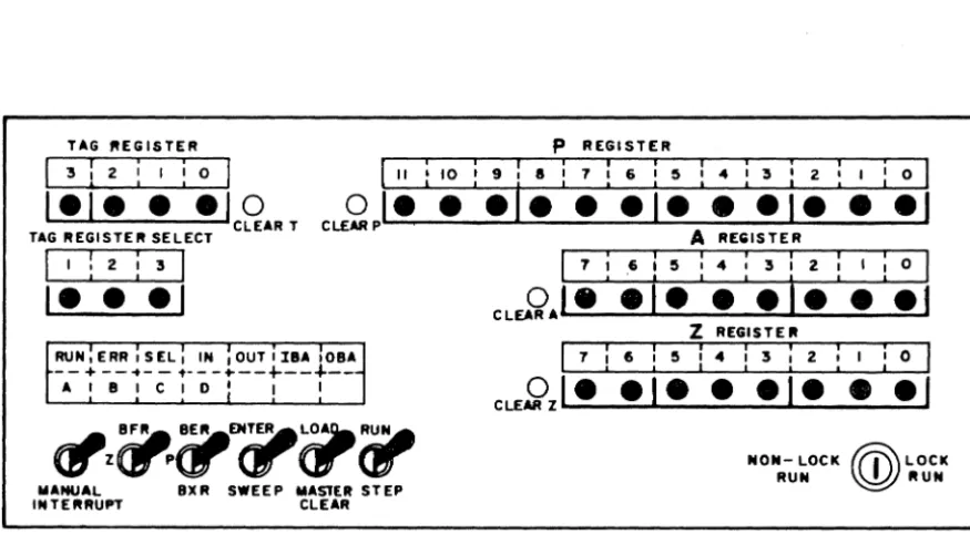
Figure 2-1 8092 Operatorls Panel
TeleProgrammer OPERATORl s CONSOLE
The 8092 TeleProgrammer Operatorls Panel consists of several displays
and switches necessary for the operation of the TeleProgrammer. The
panel (see figure 2-1) contains six display windows, six switches, and
a lock switch. Four of the display windows can display in binary the
contents of nine 8092 registers. Buttons beneath these displays clear
and enter data into the P, A, Z, and Tag registers (the only registers
into which data may be entered or cleared). A fifth window contains
information as to which Tag register has been selected. The sixth
window contains the operating lights which indicate the status of operation
[image:51.621.92.530.153.399.2]of the TeleProgrammer. At the bottom of the panel are located all the operat-ing and mode switches. The operation of these switches is explained below:
SWITCHES Manual Interrupt
BFR.Z
BER. P. BXR
-Momentary depression causes the Tele-Programmer to enter an interrupt routine to determine the nature of the interrupt. - This 3-position switch chooses the regis-ter that is to be displayed in the a-bit
Z
register display.-Y.P.. -
Displays the last word processed during the last buffer ope ration (B FR register) Center - Shows the current contents of theZ register (Z register). Down -
Not
assigned.- This 3-position switch chooses the regis-ter to be displayed in the 12-bit P regisregis-ter display .
ENTER/SWEEP
LOAD/MASTER CLgAR
RUN/STEP
Center - Displays the address of the
current instruction (P register).
Down - Displays the lowest-order 10 bits
of the LWA
+
1 of the buffer area (BXR)register. Tag 3 must be referenced for
the highest-order 2 bits of the address.
-Sweep is used to display the contents of
core storage locations. Enter is used
for entering information into core storage
from the console.
- LOAD position allows speciallyprepared
paper tapes to be read into storage by the
paper tape reader.
Master CLEAR performs a
TeleProgram-mer clear which:
a. Clears the registers
b. Clears the control flip-flops
c. Clears all waiting interrupts and
~emoves interrupt lockout.
Note: The master clear does not alter
core storage.
.Y.!L -
In RUN position, a program 1Sexecuted at high speed starting at the
loca-tion specified by the P register.
NON-RUN LOCK RUN LOCK
DISPLAYS
Z REGISTER
A Register
Center - C enter position stops the computer
program. If the switch is in RUN and an
ERR or HL T instruction is executed, the
switch must be returned to neutral and
then placed in RUN to continue computation.
Down - In STEP position, one storage
cycle of an instruction IS executed each
time the switch is set; a program may be
executed one instruction at a time for
de-bugging.
In the Lock position all other switches are
disabled and the TeleProgrammer is locked
In the RUN position.
In the non-lock position, the console switches
are enabled and the TeleProgrammer
pro-grams can be operated and modified from
the console.
- This display known as the Z register
group displays the Z and B FR registers
In accordance with the setting of the B FR ,
Z switch.
-Displays the current contents of the A
P Resister
TAG REGISTER
STATUS INDICATORS
RUN
ERR
SEL
- This display known WI the P regis&.r gr"up di.plays the BER.
p.
and BXR registers in accordance with the settingof the B ER. P, BXR switch.
- This display indicates the Tag register currently being referenced by an inatruclion.
The contents of any Tag register m oIllY be displayed by depressing one 01 the buMons directly below the .elect indioa6Drs. Oe-pressing one 01 the .eIect bulk»n. alao enabl . . the Tag regi . . . to be manually set or cleared.
-Indicates &hai the Tei.P!"OfIjJr..,m.r i. in
RUN stalus. This does not necessarily indicate that instructions are being executed. -Indicate. that a timing fault haa occurred. -Displayed each tim. 8ft
EXF
ilUltructionis ex.:utad; remain. until •• I.tion i. completed. A con ... display of BEL with no apparent il!l)ut./ output _Doa usually indie" the TeleProgrammer has Mhmp'-<l
an illegal selection.
IBA OBA
A. B. C. or D
-Displayed during all normal input
opera-tions. A constant display of IN with no
apparent input action usually indicates that
input was attempted without proper unit
selection. IN is also displayed when the
TeleProgrammer is waiting for an external
device to supply data.
Displayed during all normal output
opera-tions. A constant display of 0 U T with no
apparent output action usually indicates that
output was attempted without proper unit
selection.
Displayed during all buffer input operations.
Displayed during all buffer output operations.
Indicates which storage reference cycle will
be executed at the next operation of the
Run/Step switch. When a master clear
is performed, D is displayed indicating
that the next operation to be executed,
when the Run/Step switch is operated,
STARTING THE 8092 TeleProgrammer
1) Be sure the TeleProgrammer is plugged into proper power source and 'room temperature is within the prescribed limits.
2) Turn on the cabinet power, then turn on the power supply.
3) Master clear by momentarily pressing Load/Clear switch to
Clear.
4) When the ERR light goes out, the TeleProgrammer is ready to operate. If repeated master clears do not turn the Red ERR light off, turn off the 8092 and call maintenance.
LOADING A PROGRAM OR DATA
Paper Tape Load Format
1 ) Master Clear
2) Turn on reader
3) Insert paper tape an reader
4) Set P to starting location
5) Set Load/Clear switch to LOAD
6) Set Run/Step switch to RUN. Paper tape will load and TeleProgrammer will stop.
ENTERING DATA FROM THE TeleProgrammer CONSOLE
1) Master clear. Set Enter/Sweep switch to ENTER. 2) Set P to location into which data is to be entered.
3) Enter one word of data into the A register.
4) Set Run/Step switch to STEP, once. At this point A IS
clear and the data word is in storage and in Z.
5) If data is to be entered into consecutive locations, go to step 3 and P will be advanced by one on step 4. If data is to be entered into non-consecutive locations, clear P. Go to &tap 2.
EXAMINING THE STORAGE CONTENTS
1) Master clear. Set Enter/Sweep switch on SWEEP
2) Set P to loc ation to be examined.
3) Press Run/Step switch to STEP, once. The contents of the location specified by P will appear In Z.