Requirements for an Ubiquitous Computing
Simulation and Emulation Environment
Vinny Reynolds, Vinny Cahill, and Aline Senart. Distributed Systems Group,
Dept. of Computer Science, Trinity College Dublin, Dublin, Ireland
{Vinny.Reynolds, Vinny.Cahill, Aline.Senart}@cs.tcd.ie
Abstract—Recent years have seen the maturing of ubiquitous computing middleware and software. Accompanied by research into sensor networks and other sensor-driven applications, widespread deployment and realisation of these technologies can now be expected in the coming years. As a cheap and quick method of prototyping applications and protocols, simulation will be a key part of the development cycle for these technologies. However, existing simulators only address a subset of ubiquitous computing environments and are unsuitable for modelling the desired complexity of the domain.
This paper presents initial work on the design of a generic simulation tool suitable for the many scenarios encompassed by ubiquitous computing, such as simulation of sensors, actuators, and the environment. In addition, an emulation framework for middleware and software under development is provided which interfaces with the simulation tool. We provide a layered, flexible and modular approach to supporting the simulation of ubiquitous computing environments without constraining the simulator to one aspect of the many possible ubiquitous computing deployment scenarios. Finally, we present and discuss a proof-of-concept simulation.
Index Terms—Emulation, sensor networks, simulation, ubiquitous computing, UCSE.
I. INTRODUCTION
biquitous computing [1,2] as an area of research is an umbrella for areas of research such as ambient intelligence [3], sensor networking [4], context awareness [5] and smart spaces [6]. In addressing this area, solutions have to contend with many non-trivial problems such as dependability, large scale, physical distribution, security, timely behaviour and many others. For these reasons, designing solutions is a difficult and time consuming process and effective development is an important issue. Simulation will play a key role in the development and testing of these solutions.
Although we are not aware of a taxonomy of the typical components used in ubiquitous computing scenarios, it
appears that there is a set of abstractions that are required by the wide range of scenarios envisaged in ubiquitous computing. These common components include sensors, actuators, applications utilising these sensors or contextual information derived from them, and the environment in which these components exist. Changes in the environment or user input typically drive sensors; applications react to this input and offer feedback into the environment or the user by way of some form of actuation. What is clear from the domains involved is the large diversity of these components that actually exist. Without mentioning actual types of sensors or referring to particular sensed phenomena, sensors can be classified as being active or passive. They can be exteroceptive or proprioceptive, i.e. they can detect values internally or from the ambient environment around them, and they can act in a periodic or sporadic manner.
Presented at the First International Conference on Integrated Internet Ad hoc and Sensor Networks (Intersense 2006) © ICST
Similarly, applications can run on a PDA requiring user input, this can take the form of a program running on a server, software running on some embedded hardware mote [7] with attached sensors, or even a collection of embedded agents enabling a smart office style scenario
Actuators can be classified in a similar manner and in the general case, interesting properties such as the scope and effect of any action that takes place must be considered.
Some of the typical environments in which these applications, sensors and actuators are deployed include buildings for smart space scenarios [8], rugged terrain for environmental monitoring [9] and road networks for intelligent transportation systems [10]. All of these environments have their own unique properties and their state can play a key role in the performance and behaviour of an application. Indeed, there are few environments in which some form of ubiquitous computing could not exist.
The use of simulation technology in ubiquitous computing is of particular importance to developers and researchers alike. Many of the required hardware technologies such as cheap reliable sensors are only reaching maturity now, and many of the application scenarios are being designed with the future in mind and well in advance of the hardware actually being available. Furthermore, many of the target scenarios do not lend themselves to onsite testing, in particular, scenarios which require deployment of large numbers of nodes or devices. In addition, simulation enables researchers to
evaluate scenarios, applications, protocols and so forth without the difficulties in dealing with hardware sensors and actuators, and also offers greater flexibility since it is easy to run a set of simulations with a range of parameters.
And yet, there are very few existing simulators which are effective in modelling the entire range of scenarios mentioned above. This may be because of the broad scope of scenarios listed already, and providing a suitably general yet customisable simulator is non-trivial. Many of the current ubiquitous computing simulators are not sufficiently flexible or general enough to be adapted to the many ubiquitous computing scenarios. Typically simulators used in this domain have been adapted from some other domain such as agent or network simulation and as such neglect or simplify some of the aspects that are more common to ubiquitous computing such as sensors and the environment.
This paper presents a novel approach to modelling ubiquitous computing scenarios using the twin technique of simulation and emulation. We use simulation to model the sensors, actuators and environment, whilst proposing an emulation framework for testing of applications and middleware. The benefits of simulating sensors, actuators and the environment have been explained above. By providing an emulation framework, developers have only to write their applications once and can re-use the same code in testing and in actual deployment. Many of the applications designed for these domains are built upon existing middleware platforms and the emulation framework also provides support for this middleware. The combined approach of simulation and emulation and the interfacing between the two allows simulated hardware devices such as sensors and actuators to interact with emulated software or middleware. Since networking and communication is a key aspect of many ubiquitous computing scenarios, integration of an existing network simulator such as ns-2 [11] into our framework is a key requirement.
As previously mentioned, there is huge diversity in the number of sensors and actuators that have to be deployed. Instead of providing models or instantiations of actual sensors and actuators, we provide a technique, utilising a pipeline of filters, for modelling the characteristics and properties of sensors and actuators which is presented in detail later. Furthermore, we provide a location-based layer model that underpins all of the simulated components. Two variations within the layer model are provided. Representation layers are used to model aspects of the physical environment and other location-based phenomena, whereas reference layers are used for management of other simulated components such as hardware devices.
We have successfully designed a proof-of-concept simulation of an intelligent transportation scenario. Separate layers are used to model mobile objects (vehicles), static objects (traffic lights), sensors (GPS) and the environment (road network). In particular, the vehicles and the GPS sensors are simulated and applications running on the traffic lights communicate using an emulated event-based middleware
interface.
The paper is organised as follows. In section 2, we present related work. Descriptions of the simulator design, the layer model and the architecture follow in sections 3, 4 and 5, respectively. We present the simulated traffic scenario in section 6 and, finally, our conclusions in section 7.
II. RELATED WORK
There are several simulators already in use in ubiquitous computing. Some have been designed specifically for this domain which we will classify as being native simulators, while others have been adapted from other simulation domains such as sensor network simulation. These are classified as being non-native. A synopsis of the state of the art of these two genres is now provided in which functional requirements such as flexibility, usability and scalability are evaluated. Further analysis of the simulators support for typical native ubiquitous computing components, such as sensors, actuators, and applications is also presented.
A. Native ubiquitous computing simulators
There are few native ubiquitous computing simulators available at present. Ubiwise [12] has been developed at Hewlett Packard by Barton et al. Recently, work at Lancaster [13] by Morla and Davies has led to the development of a hybrid test and simulation environment. Further research in this field has been done at Trinity College by O’Neill resulting in the Tatus [14] simulator.
Ubiwise [12] is one of the few simulators being developed at the moment in the ubiquitous computing field. The simulator provides a "three-dimensional world, built on the Quake III Arena graphics engine, and serves to simulate a first person view of the physical environment of a user". The general theme underlying the aims of the simulator is the rapid and cheap deployment of ubiquitous devices and services, which would take too long to prototype in actual hardware.
Native support for sensors and actuators is not explicitly mentioned. Ubiwise does however support the creation of hardware ‘devices’, which can interact with the environment by way of adding physical interaction code into a dynamic link library provided with Quake. Sensors and actuators could be modelled in this manner. Applications in Ubiwise are specified through an XML device description file and associated Java .class files. Applications can communicate with external services outside of the simulated domain. The environment can be modelled as simply or as complexly as required using the Quake 'map' format. Devices and users previously defined are then located within the world.
Ubiwise provides modelling capabilities for all of the typical components identified. However although the authors claim to be interested in ubiquitous computing system design, the work is geared towards examining the user experience in a ubiquitous environment. Ubiwise has in fact been rebranded as a conceptualiser as opposed to a simulator.
multiple times. On the other hand, modelling of all the key components is flexible, if somewhat clumsy. Development of Ubiwise appears to have ceased for the moment.
The Lancaster simulator [13] attempts to provide a “new environment for testing and evaluating system and network-related issues in location-based applications”. Developed after Ubiwise, this work is more experimentally focussed. It supports actual application code, interfaces with a proven network simulator, ns and also enables live user interaction at run time. By providing separate interfaces for network and location simulation, and a Web Services based API for applications being tested, some flexibility is achieved in their approach.
Application emulation is also supported through the Web Services interface although this almost certainly introduces additional overhead. Their test environment does not focus on simulation of large scale systems, nor on the simulation of sensors and actuators which is essential for ubiquitous computing simulators
Tatus [14] is another 3-d simulator built using a similar methodology to that of Ubiwise, except that it is built upon the Half-Life game engine. Compared with Ubiwise, Tatus is a more user-centric simulator and offers the user the opportunity to experience a ubiquitous environment. Ubiwise on the other hand offers a toolkit for simulating devices. Tatus offers users the opportunity to test software before deploying it through the use of a proxy, which interfaces with the simulator.
This is comparable to emulation, but means that the software is running in a separate address space, perhaps even on a different machine.
B. Non-native ubiquitous computing simulators
SENS [15] is an application-oriented wireless sensor network simulator which models ad hoc static nodes. It provides models for a limited set of sensors, actuators, a model for the environment and a framework for testing of applications. Although not regarded as a ubiquitous computing simulator, SENS is included as it is very similar in methodology to what we are trying to achieve. SENS is designed for a signal based experimentation platform and as such a limited range of sensors and actuators are provided. No references are made as to how to add new models of sensors or actuators. SENS also tries to provide an environment modelling system for developing more realistic 'worlds'. This is however a wireless sensor network simulator so the world is constrained to being of type, ‘grass’, ‘concrete’ or ‘wall’. SENS provides a “compatibility layer to enable portability between simulated applications and real sensor nodes”, which is in effect providing an emulation environment.
SENS aims for its components to be extensible and interchangeable and it is, in terms of the wireless sensor network domain. However, the nature of the environmental model does not suggest re-usability for anything other than sensors and actuators modelling wave phenomena, making it unsuitable for modelling arbitrary ubiquitous computing environments.
C. Conclusion
Ubiwise and Tatus offer a rich model of the environment but are not designed as simulation test beds. They are perhaps better described as device or scenario prototyping test beds instead. It is not possible to run a suite of experiments where you are varying the input parameters in a simulator that requires user input. There are many motivations for simulation. The most commonly quoted are cost, and quick prototyping. Another is time. The Lancaster work and SENS focus more on the set up of the simulator tools themselves and are results oriented.
III. SIMULATOR DESIGN
The first step in the design of a simulator suitable for modelling ubiquitous computing environments is to look at requirements and from these produce a set of goals.
It has been noted that many of the typical scenarios deal with issues such as large numbers of devices, possibly physically distributed over a large geographical space, hardware problems involving many types of sensors and actuators and the many application frameworks that may use such devices and be running in the space. The simulator for ubiquitous computing must reflect these issues in its goals and design. In the simulator that we have designed, four key abstractions are addressed: modelling of sensors and actuators, enabling an application framework and modelling the environment.
A. Simulator Goals
Given the diversity of the aforementioned scenarios, any simulator that attempts to model the abstractions identified above must be flexible and sufficiently general yet extensible enough in its base model to support these. However, a tool that attempts to be too high-level risks being unusable and leads to ‘hacking’ of models. This happens all too frequently when simulators do not accurately meet the domain requirements and result in bad software engineering. Another goal critical to simulators is the provision of an accessible and usable environment which exposes a complete interface in an intuitive manner, therefore usability or ease of use is a second goal. Large scale is such an important aspect of many of the scenarios identified, and is such a non trivial problem that supporting scalability is a third and final goal of the simulator.
Lack of flexibility is one of the common problems in many of the simulators in use at the moment. Ubiwise is clearly well suited to providing a rich model of a smart space environment but would not be suitable for running a series of experiments on a sensor network. Similarly SENS provides an accurate model of network behaviour in sensor networks, but users are forced to use a specific SENS API for any applications which run on top of these sensor networks.
that ns-2 is flexible. This type of flexibility is one of the key goals of the simulator. Furthermore, all types of sensors and actuators must be supported. Any environment, whether it is the smart space or an intelligent road network must be supported by an environmental model. In section 4, a layer model is introduced which addresses this goal. Flexibility in the modelling of each of the ‘typical’ ubiquitous computing components is detailed later in this section.
When accounting for usability in simulation, there are several design factors that have to be made. The key factor is that it has to be easy for the user to get what they want. This is typically experimental results or verification. To enable this, the design of the simulator should be as ‘open’ as possible. By open, we mean that every component is accessible and replaceable to the user. And that in the case of the user not wishing to address some aspect of a simulation, a default implementation is always available. For example, one user may wish to use ns-2 for an accurate representation of the process by which messages are passed, but another user may not. This will allow users to get up and running quickly when designing their simulations.
Another important aspect from the users’ perspective is the actual process by which the results are obtained. This is addressed in the system architecture, where a log manager is provided as an interface between users the simulated domain.
There are two interpretations of scalability in terms of simulation of ubiquitous computing environment. The traditional and classical interpretation is that many ‘devices’ must be supported, for some interpretation of device whether that be a sensor mote or an mobile agent. The second interpretation is that there may be many different types of devices, different types of sensors, different types of applications running on different middleware with different requirements. Supporting the two interpretations of scalability is a key goal of this simulator design.
B. Simulated components
Four common abstractions of ubiquitous computing scenarios were identified earlier: the environment, sensors and actuators and applications. The methods and design for modelling each of these components within the simulator is now presented.
It has been noted that ubiquitous computing can conceivably take place within any type of environment or space, and as such the model of the environment provided must be sufficiently general that it can be adapted to the many scenarios required. The main property of all environments and objects within those environments is location. Using location as the inspiration,, a grid-based approach to modelling the environment is provided. This modelling of an environment is achieved using a combination of representation layers, the design of which are described in detail in the following section. Representation layers are used to model all phenomena that may be sensed as well as the purely physical aspects of the environment, i.e., reference layers refer not only to physical components such as the topology of the ground, or
the presence of buildings or roads but also phenomena such as the light levels at a particular location, or the noise or the temperature at a particular location within the environment
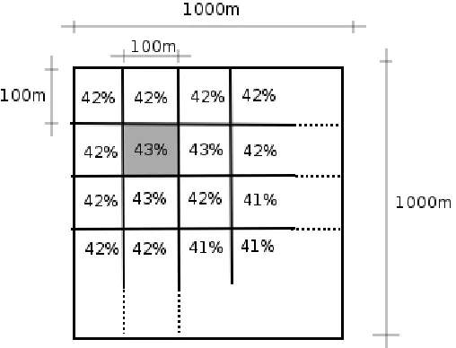
[image:4.612.313.567.100.294.2]
Fig. 3. A single representation layer with a world size of 1km2 and a
granularity of 100m. The layer models relative humidity in the environment.
Sensors can have a wide range of characteristics and properties. The method provided for modelling sensors only addresses their most fundamental characteristics. These characteristics are
• Whether the sensor is active or passive • Internal or external measurements • Periodic or sporadic occurrences
Even sensors of the same type have unique properties and levels of accuracy and so forth. A flexible method for modelling these properties is to use a sensor pipeline, displayed in Fig 1, comprising of a combination of filters which may ‘modify’ or ‘block’ the measurements in some way. The initial measurement or sensor reading is made when the sensor retrieves or ‘senses’ data from a reference layer modelling the sensed phenomenon using one of the
retrieve() methods implemented by the layer. This initial value is then pushed onto the sensor pipeline where it passes through the filters. ‘Modifying’ filters may update the value in some way by adding some error based on a Gaussian distribution for example. A ‘blocking’ filter determines if it was possible that the reading actually was possible to make, and may take the location of the sensor and the distance to the sensed phenomenon into account for example. By combining many of these filters into a single conceptual pipeline, through which all sensor measurements must pass, it is possible to provide a very accurate model of a sensor.
Fig 1. The process by which a reading passes through a pipeline formed of a combination of blocking and modifying filters
Internal and external values or proprioceptive and exteroceptive sensors take readings from a co-located phenomenon or from an external source. Two examples would be a GPS sensor measuring its’ own location, or a thermistor measuring the ambient temperature in the room. Proprioceptive sensors are bound to the phenomenon that they are measuring using a unique identifier which is specified by the programmer at design time. Exteroceptive sensors are bound to a layer which models the phenomena and at run time a look up is performed into the layer to ‘sense’ the phenomenon.
Actuators are modelled using a similar methodology to the sensors. They are characterised in the same way, they may be periodic or sporadic, act internally or externally and so forth. They are also modelled similarly within the simulator. A pipeline of filters again used, except that logically the process happens in the opposite direction. In the actuator pipeline, the actuator alters some phenomenon and this updates the state of some variable or state representing some other aspect of the simulated environment. We again use the pipeline and use the notion of blocking and modifying filters to increase the fidelity of the model. The ‘effect’ of the actuator passes through the pipeline before the actuation actually occurs and some state is updated.
Both sensors and actuator events can occur in a periodic or sporadic fashion. These are handled differently in simulation framework. Periodic devices queue an event themselves in the event queue and at the appropriate time, an event is executed. At the time of execution, the next periodic event is scheduled. Sporadic events are driven by the execution of an alternative event and occur arbitrarily. Therefore sporadic events are never scheduled but are the result of the execution of another event.
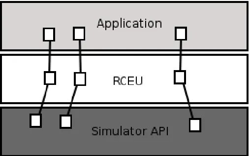
Application code is written by users that forms a part of the ubiquitous computing scenario. It is a common, but an unfortunately inefficient practice that this code is typically written once for the simulation of that environment and is then rewritten at the time of actual deployment. This occurs because most simulators do not provide an API for the application being developed. One of the goals of the simulator is to address this issue. By providing an emulation framework, it is intended that researchers only have to write code once for simulation and can then re-use the same code without modification at actual deployment. Since flexibility is a key
goal of the simulator, this emulation framework must be replaceable. This simulator proposes using a Replaceable Code Emulation Unit as a methodology of supporting multiple application API’s.
Fig. 2. The split level API. The Replaceable Code emulation unit acts as a binding between the application API and simulators API and binds calls from the application to the appropriate function in the simulator
This is achieved using a split level design illustrated in Fig. 2. The simulator API exists at the base level which interacts with all the simulated components such as the sensors and actuators, and well as the rest of the simulator architecture. A mid-level API then sits above the base level and interacts between the application and the simulator. This mid-level component ‘binds’ calls from the application to the corresponding calls within the simulator. The libraries upon which the application is based have to be rewritten in order to do this. These rewritten libraries then sit at this mid-level. Using this methodology, the simulator is in fact transparent from the application.
Although this approach requires an initial overhead in coding, it is envisaged that these ‘bindings’ will only have to be written once and that over time a library of common bindings can be produced, i.e., one binding for the STEAM middleware [16], one for TinyOS, and so on, all of which are shared and can be reused by researchers. A default implementation of the mid-level API will also be provided which makes a direct mapping from the application to the simulator.
IV. THE LAYER MODEL
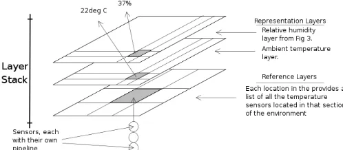
[image:5.612.313.567.111.269.2]between these layers are specified by simulator users. This collection of layers is the representation of the domain being modelled by the user.
[image:6.612.46.295.186.295.2]Conceptually, a layer is a two-dimensional grid of fixed size which maps onto the scenario being modelled. Two types of layers are provided in the simulator: representation and reference layers. At the time of creation, all layer types are parameterised to represent the scale of the environment desired, as well as the granularity of the grid within the layer.
Fig. 4. The Layer Stack comprising of two representation layers and a single reference layer. Note the fixed world size and the variable granularity.
A. Representation Layers
Representation layers are used to model aspects of the physical environment. In a sensor networking scenario, a single layer might represent the type of ground across the simulated environment, such as whether it was concrete or grass and so forth. The granularity of this detail could typically be 10m. A second layer in this scenario might represent a model of the moisture levels in the air across the simulated environment. The granularity of this detail could be as large as 100m for example.
Layer creators must implement a populate() method which instantiates the phenomena represented at each part of the layer and a transform() method which is called to update the state of the layer.
B. Reference Layers
Reference layers are used to support the management and storage of simulated components already created such as sensors and actuators. A dedicated layer is created for the management of each type of component created, and each component is stored within the layer at a particular location within the grid. The use of a location-based reference mechanism for management and storage of components ensures greater scalability. The simulator exploits the location information to bound the amount of interactions that can occur between devices. A similar method was introduced in [17] to achieve greater scalability in ns-2.
The combination of simulated components, reference layers for management of those components, and representation layers for modelling the environment provides the basis for simulating most scenarios. As the user specialises the simulation to their own requirements, they may have to define
their own domain specific component types and support for this is also provided in the reference layer model.
It is envisaged that potentially interaction can occur between almost any of the layers and the components stored within the layers and therefore the interaction between layers is loosely coupled so as not to constrain any simulation.
An implicit binding between simulated components and layers also exists which must be addressed. For example, a representation layer of thermistor sensors which take temperature measurements should be bound to a representation layer which models the temperature of the environment. The layer model supports a naming system to provide this binding transparently to users.
An interesting interaction to note is between different environment layers. It has already been stated that dependencies may be built up between different representation layers. This should be quite common if users are hoping to model a complex environment, as conceptually so many layers are actually interdependent. Precipitation can lead to moisture which can lead to decreased wireless transmission ranges for example. This dependency is captured within the layer API. As a user implements the transform() method, he may query other layers using the current location as the key to determine the state of any other layers. Thus, a layer modelling the wireless transmission range of a wi-fi card, may query the layer representing the precipitation using the location of the wi-fi card to retrieve the correct precipitation level at its location. Theoretically, we hope that users would be able to model any level of detail or complexity required using this model.
C. Data retrieval within layers
There are two primary methods for retrieving data from within layers. As noted, location is a common property for many of the simulated components. More specifically, all components have either an explicit location, or they are associated with an component which has an explicit location, i.e. the two entities are co-located. Components with a relative location have two potential accessors. A component may be physically collocated but may still interact with other components as if it had its own explicit location. An example of this would be a sensor attached to some mobile device (of which it has no control), and which is broadcasting its sensor events for anybody who is listening.
The layer API should therefore support two access methods. The first uses location as the key. For example, a sensor queries an environmental layer for an attribute at a certain location, or the simulator obtains a list of potential recipients of a transmitted message based on the location of the sender.
attached, such as an accelerometer. In the layer model, the sensor and sensed entity are represented independently (in separate layers), so if the sensor was to query a representation layer, it would have to use the represented object itself as the key, and would then have to query the sensed property of the returned object. From these observations, we have defined a layer API with the following accessors.
class Layer{
someType retrieve(Location);
someType retrieve(entityID, property); }
Fortunately this data retrieval can be abstracted away from users by using the naming and binding service mentioned earlier. This is performed by the layer manager which is described in Section 5.
V. SIMULATOR ARCHITECTURE
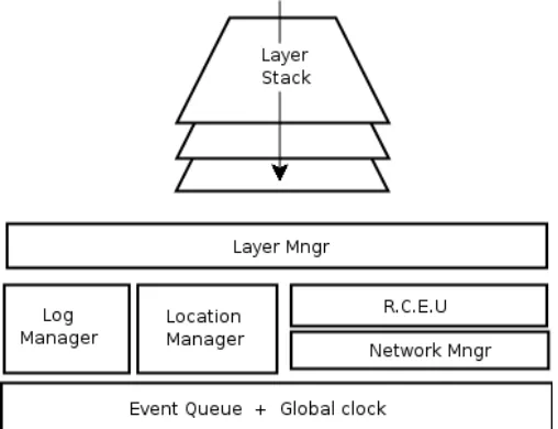
[image:7.612.47.301.352.547.2]Several components are required to support the simulator as it has been described so far. These components are a layer manager, Replaceable Code Emulation Unit, network manager, location manager, log manager, event queue and global clock. The role that these components play is described now in detail.
Fig 5. The simulator architecture showing the key components
The layer manager has several responsibilities. As well as being a registration point for all layers created, it also manages the interactions between layers which have interdependencies. As changes occur in a layer, dependant layers are scheduled to update their state if required. The layer manager is also responsible for scheduling periodic updates to layers in the event queue. When an update is due, the appropriate
transform() method for the layer is called by the layer manager. The layer manager provides a naming service as it also maintains any bindings that are required between sensors and layers representing sensed phenomena, and actuators and modifiable phenomenon. Furthermore, the layer manager monitors the modelled environment for changes which a
passive sensor may then sense.
The functionality of the Replaceable Code Emulation Unit (RCEU) is described in detail in Section 3. Although applications sit above the RCEU in the architecture, they may also maintain a logical location within a representation layer. This is common enough as many ubiquitous computing applications are location based. Any actual physical hardware associations between applications, sensors and actuators is maintained in the layer manager using the naming and binding service.
Network simulation can be a key component of accurately simulating ubiquitous computing environments. We provide a network manager to interface between our simulator and a network simulator. Within the RCEU, any calls that are made to the network are intercepted and redirected through the network simulator, whereby the communication mechanism is simulated and the message is delivered to its final recipients. This network manager will interface with the subset of layers that represent communicable devices. Within the network manager, the network simulator may also interface with the location manager component to provide locations of networked nodes thus providing optimised simulation of communication.
The location manager interfaces with the layer manager to track mobile components and inform the layer manager of important changes. For example, when a device moves from one grid to another within a layer. Doing this in a just in time or a proactive manner remains an evaluation criteria. Effective location management of components is expected to play a large role in simulation efficiency and in enabling scalability [17]
Achieving the desired simulation output in an easy and efficient manner is another important requirement for an effective simulator. A log manager is provided, in which users can register their interest in state that they wish to have monitored. This log manager interfaces with the layer manager to monitor this state and can output logged results when required.
A standard event queue and global clock within the DEVS [18] simulation formalism is provided to run the simulator. Events are scheduled to occur in the event queue and as the simulation clock iterates, events are taken from the queue and processed.
and actuator interaction.
VI. RESULTS
We have successfully designed a proof-of-concept simulation of an Intelligent Transportation Systems (ITS) scenario. The ITS scenario is a typical ubiquitous computing scenario if on a scale larger than is normally envisaged. In this simulation, smart traffic lights attempt to increase the vehicle throughput at a junction by using a collaborative reinforcement learning technique. The traffic lights communicate to share state information and attempt to find global optimisation through making localised changes. The localised change that occurs is that a particular traffic light alters its light sequence to prioritise one flow of traffic over another.
The ITS scenario was chosen as the proof of concept prototype because it addressed many of the characteristics of ubiquitous computing scenarios. All of the common abstractions that we identified are present: sensors (GPS), actuators (traffic lights), applications controlling both the traffic lights and the sensors and a rich, complex and accurate physical road environment as well. Finally, the ITS scenario presents the problem of scale.
The area of Dublin being simulated is approximately 80sq km and the number of vehicles being simulated is in the order of 10s of thousands. Simulated vehicles are equipped with a GPS sensor and periodically broadcast this information using an emulated event based middleware framework. Traffic lights within a designated transmission range (250m) receive these events, update their internal representation of the congestion load in the road network and then alter their light timing sequence to optimise the flow of traffic. Using the same emulated event based middleware, the traffic lights then communicate with their neighbouring traffic lights to share their congestion information and any other state shared in the collaborative reinforcement learning protocol.
[image:8.612.314.566.50.209.2]Several of the typical components identified in ubiquitous computing scenarios are used in the ITS scenario. Representation layers are used to maintain simulated vehicles, which are mobile objects running applications, the location of the GPS sensors and the location of the traffic lights, which are static objects running applications. A reference layer is used to maintain a model of the road network which is the simulated environment in this case. A wide-scale picture of the layer is provided in fig 6. Although no network simulator was incorporated into this proof-of-concept, a location manager was implemented which, using the grid based location of vehicles and traffic lights, was able to reduce the number of messages that were passed when simulated communication took place.
Figure 6. A section of the Dublin area road network. This is about 3000 links and 600 traffic lights
Only a single reference layer was used in this simulation. A user could extend this model very simply to generate a far more complex model. Using the single reference layer (road network model) and the vehicle location representation layer as sources, it would be very easy to create a dependant reference layer that simply tracked the number of vehicles in a grid of 500 m2 block. This layer could be used as a source of traffic congestion for one simulation. In an alternative simulation though, that new congestion layer could be the basis for a representation layer modelling the amounts of pollution over various parts of the city, which is the input for a carbon monoxide sensor.
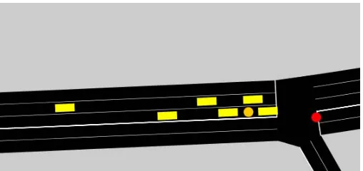
Fig 7. A detail from the simulation showing vehicles queuing at a junction displaying a red traffic light.
By simply adding more layers, and programming simple dependencies between them it is quite easy to build up complex models using the layer model and the layer stack.
[image:8.612.313.567.400.520.2]suggests that the simulator has achieved its goals of flexibility and usability.
VII. CONCLUSIONS
We have provided a simulator for modelling a wide range of ubiquitous computing scenarios. Through a flexible model reflected in the layered architecture, this simulator can be used to simulate many scenarios in a more complete manner than has been possible before. The sensor pipeline and actuator pipeline model, as well as layer stack enable greater flexibility in modelling components and does not constrain users in any way.
Similarly, the novel use of a split level API to enable emulation of multiple application frameworks is a significant contribution to the ubiquitous computing simulation community. We believe our goals of flexibility, usability and scalability are reflected in the architecture and the methods provided. The proof-of-concept traffic simulation provided demonstrates the achievement of some of these goals.
We have yet to evaluate our approach experimentally to verify our methods. We hope to evaluate questions such as the overhead in using the layer model vs increases in simulator performance. Usability is a key goal of this work, so we are also interested in evaluating to what degree the models provided assist users developing simulations. These experimentations and further development of the simulator will form the basis of work on the simulator in the foreseeable future. Experimental evaluation of the traffic simulation is being carried out at the moment.
Simulation of ubiquitous computing scenarios is still in its infancy and many simulators including this one require more research and development. By starting at the bottom however and attempting to model fundamental components and working our way up, we hope that this simulator will enjoy some success as development increases.
VIII. ACKNOWLEDGMENTS
The authors are grateful to Science Foundation Ireland for their support of the work described in this paper under Investigator aware 02/IN1/I250 between 2003 and 2007.
REFERENCES
[1] Mark Weiser, “The Computer for the 21st Century”. Scientific American,
Vol. 265, No. 3, pp. 94-104, September 1991.
[2] Mark Weiser, “Some Computer Science Issues in Ubiquitous Computing”, Communications of the ACM, Vol. 36, No. 7, pp 74-84, 1993.
[3] Paolo Bresciani, Loris Penserini, Paolo Busetta and Tsvi Kuflik, “Agent Patterns for Ambient Intelligence”. In Proceedings of 23rd International
Conference on Conceptual Modelling, November 2004, Shanghai, China.
[4] Tian He, Sudha Krishnamurthy, et al., “Energy-Efficient Surveillance System Using Wireless Sensor Networks”. In Proceedings of 2nd
International Conference on Mobile Systems, Applications and Services (MobiSys'04), June 2004.
[5] Massimo Benerecetti, Paolo Bouquet, and Matteo Bonifacio, “Distributed Context-Aware Systems”. In Human-Computer Interaction, Vol. 16, 2001.
[6] Alan Dearle, Graham Kirby, Ron Morrison et al., “Architectural Support for Global Smart Spaces”. In Proceedings of 4th International Conference on Mobile Data Management, Vol. 2574, 2003.
[7] www.xbow.com, Crossbow Technology Inc. Pages on wireless sensor networks.
[8] Emmanuel Munguia Tapia, Stephen S. Intille and Kent Larson, “Activity Recognition in the Home using Simple and Ubiquitous Sensors”. In Proceedings of 2nd International Conference on Pervasive Computing, Vienna, Austria, 2004.
[9] Xiang Ji, Hongyuan Zha, “Sensor Positioning in Wireless Ad-hoc Sensor Networks Using Multidimensional Scaling”, Proceedings of IEEE INFOCOM, pp. 2652-2661, 2004.
[10] Lawrence A. Klein. “Sensor Technologies and Data Requirements for ITS”. Artech House, 2001.
[11] http://www.isi.edu/nsnam/ns, NS-2 simulator, 2001.
[12] John J. Barton and Vikram Vijayaraghavan, “UBIWISE, A Ubiquitous Wireless Infrastructure Simulation Environment”,
http://www.hpl.hp.com/techreports/2002/HPL-2002-303.html
[13] Ricardo Morla, Nigel Davies, “Evaluating a Location-Based Application: A Hybrid Test and Simulation Environment”. In Proceedings of 2nd International Conference on Pervasive Computing,
Vienna, Austria, 2004.
[14] Eleanor O'Neill, Martin Klepal et al., “A Testbed for Evaluating Human Interaction with Ubiquitous Computing Environments”. In Proceedings of 1st International Conference on Testbeds & Research Infrastructures
for the DEvelopment of NeTworks & COMmunities (TRIDENTCOM 2005), Trento, Italy, February 2005.
[15] Sameer Sundresh, Wooyoung Kim and Gul Agha, “SENS: A Sensor, Environment and Network Simulator”. In Proceedings of IEEE/ACM Annual Simulation Symposium, 2004.
[16] René Meier and Vinny Cahill, “STEAM: Event-Based Middleware for Wireless Ad Hoc Networks”. In Proceedings of International Workshop on Distributed Event-Based Systems (ICDCS/DEBS), 2002.
[17] Valeri Naoumov, Thomas Gross, “Simulation of Large Ad Hoc Networks”. In Proceedings of ACM Modelling, Analysis and Simulation of Wireless and Mobile Systems (MSWiM), 2003.