© 2019, IRJET | Impact Factor value: 7.34 | ISO 9001:2008 Certified Journal
| Page 627
A Paper on the Analysis of Vibration to the Passenger Seat
Nikhil Kishor Toke
1, Pavan Vilas Kolate
2, Pooja Valmik Mahajan
3, Latika Bhalchandra Patil
41,2
Student, Department of Mechanical Engineering, SVIT Nashik, Maharashtra, India
3,4Student, Department of Mechanical Engineering, S.N.J.B’s Chandwad, Maharashtra, India
---***---Abstract -
This paper deals with the analysis of vibrations to the passenger seat through the irregularities on road surface. This analysis is carried out with the help of FFT analyzer for different classes of passenger car for variety of road conditions which have been validated by TOPSIS Tool. And also to identify the various parameter which directly affect the ride comfort of car and also study of these parameters. This study also involve the comparison of various reading taken with FFT analyzer with analytical method using the TOPSIS tool and gives the more better results and conclusionsKey Words:FFT analyzer, TOPSIS.
1. INTRODUCTION
Many people nowadays spend a significant proportion of their time travelling and there is an increasing demand for comfort tin private and public transportation. A good ambience results in better performance by the driver, improving the safety of all the occupants. Also the fatigue of passengers following a journey will be significantly diminished if good ride conditions are provided. Three classes of factors are considered in the analysis of travelling comfort: organizational, local, and riding. To derive riding comfort, such factors as habitat, the vehicle, the vibration, and human must be considered when evaluating a car. However, realistically understanding riding comfort is difficult. It is also difficult to obtain evaluation results that can be fed back to the design stage. The present study targeted the driver who received the vibrations. The sense of the person who causes by this vibration is narrowly treated as riding comfort. Riding comfort is a subjective psychology response, although an objective evaluation approach is necessary as mentioned above. Because experts have done traditional evaluations, no objective evaluation indexes and universal development indicators have been done.
Ride comfort affect not only the comfort of the crew, work performance and physical health, but also directly or indirectly affect the vehicle's power, economy and handling performance. Ride Comfort is the general sensation of noise, vibration and motion inside a driving vehicle, experienced by both the driver as well as the passengers. Design of advanced suspension systems is one of the requirements, which provide comfortable ride by absorbing the road disturbances as well as maintain the vehicle stability. Hyperventilation, disorders of the back like back pain, osteoarthritis, slipping of disc etc. have commonly been associated with exposure to vibration.
Vehicles travel at various speeds and experience a large spectrum of vibrations. Due to road roughness and vehicle vibration, occupants are subjected to accelerations in different directions, which causes discomfort. Such vibrations are transmitted to the vehicle passengers as a result of their contact with the seat, steering wheel, and foot rest. Therefore, occupant comfort is directly associated with the ride performance of a road vehicle. Ride comfort evaluation is a major issue in the analysis of vehicle dynamics.1 As a necessary part of simulation-based vehicle design, the theory of rigid multibody dynamics methods has been widely applied to assess ride comfort. However, due to the inevitable deformations of flexible parts of road vehicle, the application of rigid multibody dynamics has been found to be not sufficient to predict accurate results.2 The suspension is one of the most important subsystems in terms of vehicle dynamics performance, especially for the ride and handling. Nevertheless, the deformations of the upper/lower control arms and other key parts of the suspension are generally neglected in the rigid multibody dynamics analysis. Therefore, the flexibility of the suspension structure is taken into consideration to make an accurate analysis of the ride comfort evaluation
.
1.1 Literature Survey
[1] “ Ride comfort evaluation for road vehicle based on rigid-flexible coupling” in this paper the Guangqiang Wu, Guodong Fan, and Jianbo Guo works on comparison between ride comfort analyses of two vehicles including rigid and rigid-flexible coupling multibody vehicle models is done. the two models of car ie. Rigid and Rigid flexible multi body coupling vehicle model and these models were built in the ADAMS/CAR software and the simulation were carried on the B type road ( For B level road, the average value of displacement power spectral density coefficient Gq(n0) is 64 × 10−6 m3) and the furture comfort testing is done Parameters :- frequency, amplitude, acceleration. Based on the comparison between ride comfort analyses of the two models, it can be concluded that the application of the rigid-flexible multibody dynamics can lead to a measurable improvement on the accuracy of the ride comfort evaluation.
© 2019, IRJET | Impact Factor value: 7.34 | ISO 9001:2008 Certified Journal
| Page 628
measurement error due to elastic component can be as highas 15% and the comfort testing of the vehicle is obtained. PARAMETER :- Mass, length, edge. Most of the experiment data are provided in a form of subjective response and the corresponding acceleration range.
[3]” Simulation Testing Research on Ride Comfort of Vehicle with Global-coupling Torsion-elimination Suspension 1” in this paper the W. Tong, K. H. Guo works on the ride performance of vehicle with torsion elimination suspension is also same as original thus the torsion- elimination suspension will not bring any efforts to ride comfort of vehicle. in this system the vehicle torsion-elimination suspension is also the same as original vehicle were respects are accelerated to testing speed of 10,20,30,40,50 & 60km/hr and ran through a triangle a bump road and the comfort zone of the vehicle is obtain. The research revealed that this suspension could even vertical loads of each wheel, reduce the torsion of vehicle body and improve the wheel ground adhesion.
[4] “
Multimodal approach to automobile driving comfort :the influence of visual setting on assessments of vibro-acoustic comfort in simulators” MaëlAmari, Etienne Parizet, Vincent Roussarie. In this paper they measure vertical vibrations by using accelerometer ,they perform exp. On 8 vehicles and 2 roads.[5] The paper “Frequency-Domain Simulation And Analysis Of Vehicle Ride Comfort Based On Virtual Proving Ground”, in this paper JieGao, Ke Chen states that, a multi-body dynamics simulation virtual vehicle model and a random road surface model are established based on VPG. LS-DYNA is used to solve simulation results. The main parameters of the actual vehicle and the simulation model studied in this paper 1. VEHICLE QUALITY , 2. ENGINE TYPE , 2. TYRE SIZE , 3.TRACK And The analysis of time-domain can accurately reflect the change of vehicle preferences with time and its results can be directly compared with real vehicle test data and the analysis of frequency domain can be directly obserb through a distribution amplitude.
[6] “ Simulation And Analysis Of Full Car Model For Various Road Profile On A Analytically Validated Matlab/Simulink Model” proposed by A. Mitra and team In this work the methodology was developed to design a passive suspension for a passenger car for satisfying the two conflicting criteria viz. Ride comfort and Road holding. Mathematical modeling has been also performed using a seven degree-of-freedom model of the full car for passive system.
[7]“PyTOPS :A Python based tool for TOPSIS Vinay Yadava and team . The Technique for Order Preference by Similarity to Ideal Solution (TOPSIS) method determines the best solution from a set of alternatives with certain attributes. The best alternative is chosen based on its Euclidean distance from the ideal solution. TOPSIS is widely used in various multi-attribute decision making problems such as supply chain logistics, marketing management, environmental management or chemical engineering. Despite the extensive
use of this method, there is no free and open-source software (FOSS) for TOPSIS with comprehensive post-analysis extensions. Therefore, this paper describes a Python-3 based tool PyTOPS for TOPSIS with the Berkeley Software Distribution (BSD)-3-Clause license.
[8] “A-TOPSIS –An approach Based on TOPSIS for Ranking Evolutionary Algorithms” Renato A. Krohlinga,b*, André G. C. Pachecob. In this paper, we propose an alternative novel method based on the Technique for Order Preference by Similarity to Ideal Solution (TOPSIS) to solve the problem of ranking and comparing algorithms. In evolutionary computation, algorithms are executed several times and then a statistic in terms of mean values and standard deviations are calculated. In order to compare algorithms performance it is very common to handle such issue by means of statistical tests. Ranking algorithms. In this case, the alternatives consist of the algorithms and the criteria are the benchmarks. The rating of the alternatives with respect to the criteria are expressed by means of a decision matrix in terms of mean values and standard deviations. A case study is used to illustrate the method for evolutionary algorithms. The simulation results show the feasibility of the A-TOPSIS to find out the ranking of algorithms under evaluation
1.2 Materials and Methods:
After selection of different categories of road vehicle, ISO 8608(1995) road profile classifications referred and accordingly variety of road profiles in the vicinity of research institute is selected. These roads are categorized as class A, B and C i.e. good, average and rough road respectively according to ISO 8608 (1995). The state-of-the-art ADASH 2-channel FFT analyzer with appropriate instrumentation is used -for the ride comfort analysis
We selected the different categories of road profile.
The FFT analyzer with appropriate instrumentation is used for the ride comfort analysis.
The metal plate is placed and fixed on the passenger seat upon which an accelerometer is mounted.
After this arrangement, the vehicle is made to travel at an average speed of 50-60 km/hr on selected class of road terrain.
The displacement, velocity and acceleration response curves are obtained on FFT analyzer. The results from FFT analyzer are then exported to the TOPSIS Tool.
© 2019, IRJET | Impact Factor value: 7.34 | ISO 9001:2008 Certified Journal
| Page 629
According to the TOPSIS results, the comparison ismade between all the selected vehicles for different road profiles.
1.3 TOPSIS
The objective of this work is to develop TOPSIS method for car selection. In order to comply with collecting quantitative and qualitative data for TOPSIS car selection model that could be applied by a seven steps approach was performed to ensure successful implementation.
Methodology used in TOSIS:-
The TOPSIS procedure is based on an intuitive and simple idea, which is that the optimal ideal solution, having the maximum benefit, is obtained by selecting the best alternative which is far from the most unsuitable alternative, having minimal benefits . The ideal solution should have a rank of ‗1‘ (one), while the worst alternative should have a rank approaching ‗0‘ (zero). As ideal cars are not probable and each alternative would have some intermediate ranking between the ideal solution extremes. Regardless of absolute accuracy of rankings, comparison of number of different cars under the same set of selection criteria allows accurate weighting ofrelative car suitability and hence optimal car selection. Mathematically the application of the TOPSIS method involves the following steps.Step 1:Establish the decision matrix
The first step of the TOPSIS method involves the construction of a Decision Matrix (DM).
--- (1)
Where ‘I’ is the criterion index (i = 1 . . . m); m is the number of potential sites and ’j’ is the alternative index (j= 1 . . . n).
The elements , …, refer to the criteria: while , …, refer to the alternative locations. The elements of the matrix are related to the values of criteria ‘I’ with respect to alternative ‘j’.
Step 2: Calculate a normalised decision matrix
The normalized values denote the Normalized Decision Matrix (NDM) which represents the relative performance of the generated Design alternatives
NDM= = --- (2)
Step 3: Determine the weighted decision matrix
Not all of the selection criteria may be of equal importance and hence weighting were introduced from AHP (Analytical Hierarchy Process) technique to quantify the relative importance of the different selection criteria. The weighting decision matrix is simply constructed by multiply each element of each column of the normalized decision matrix by the random weights.
V= = × --- (3)
Step 4:Identify the Positive and Negative Ideal Solution
The positive ideal (A+) and the negative ideal (A-) solutions are defined according to the weighted decision matrix via equations (4) and (5) below
PIS = = { +, +…, +}, where: +={(maxi (Vij) if j '---(4)
NIS =
---(5)
Where, J is associated with the beneficial attributes and J' is associated with the non-beneficial attributes.
Step 5:Calculate the separation distance of each competitive alternative from the ideal and non- ideal solution
--- (6)
--- (7)
Where, i = criterion index, j = alternative index.
Step 6:Measure the relative closeness of each location to the ideal solution.
For each competitive alternative the relative closeness of the potential location with respect to the ideal solution is computed.
Performance ( )= ---(8)
Step 7: Rank the preference order
© 2019, IRJET | Impact Factor value: 7.34 | ISO 9001:2008 Certified Journal
| Page 630
1.4 FFT ANALYZER
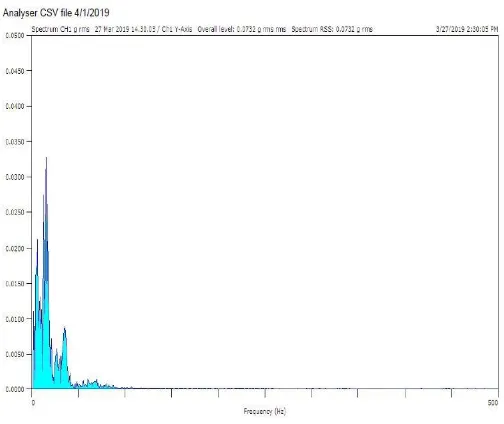
The resulting digital time record is then mathematically transformed into a frequency spectrum using an algorithm known as the Fast Fourier Transform, or FFT. The FFT is simply a clever set of operations which implements Fourier's theorem. The resulting spectrum shows the frequency components of the input signal.
The vibrations produced in a car are indicated by the device known as FFT (fast Fourier Transform) it indicates the vibrations in the form of graph and any waveform is actually just the sum of a series of simple sinusoids of different frequencies, amplitudes, and phases
2. EXPERIMENTATION DONE:-
Test 1
[image:4.595.310.562.89.301.2]Vehicle Type: - Hatchback Vehicle Model: - Vista Tyre Pressure:-32 Windows:-All Closed Music System:-Off -Air Conditioning:-On Weight:-1135+220 kg Noise level:-62 db
Table 3:- Readings of Vista
Vehicle Type Road Type Acceleration Hatchback Case1(Good) 0.105 Hatchback Case2(Average) 0.209 Hatchback Case3(Rough) 0.338
Graph 1:- Graph of Vista on Good road
Graph 2:- Graph of Vista on Average Road
Graph 3:-Graph of vista on Rough Road
2.1 Input Tables
Criteria Parametric Value for Hatchback and Sedan
Car
© 2019, IRJET | Impact Factor value: 7.34 | ISO 9001:2008 Certified Journal
| Page 631
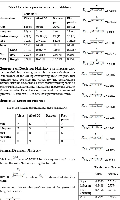
Table 11:- criteria parametric value of hatchbackElements of Decision Matrix:-
This all parameters are devided into two groups, firstly we calculate the performance of the car by considering style, lifespan, fuel economy, cost. We give the values for this performance characteristics in above tables, after that we ranking them by considering a suitable range. A ranking is in between the 1 to 10. We consider Rank 1 is very poor and this is increased upto rank 10 and rank 10 is very best performance rank.Elemental Decision Matrix
:-Table 13:-hatchback elemental decision matrix
Normal Decision Matrix:-
This is the step of TOPSIS. In this step we calculate the Normal Decision Matrix by using the formula
NDM=Rij= , where is element of decision matrix
It represents the relative performance of the generated Design alternatives
= =0.6363
= =0.5433
= =0.7155
= =0.5321
= =0.5183
= =0.7774
= =0.7155
= =0.6225
= =0.5183
= =0.4484
= =0.4850
= =0.6225
= =0.6363
= =0.5433
= =0.3904
[image:5.595.40.435.72.729.2]= =0.5321
Table 14 :- Normal Decision Matrix
Vista Alto 800 Dats-on go Fiat
punto Weightage Style 0.6363 0.5183 0.5183 0.6363 0.1 Lifespan 0.5433 0.7774 0.4484 0.5433 0.4 Fuel
economy 0.7155 0.7155 0.4850 0.3904 0.3 Cost 0.5321 0.6225 0.6285 0.5321 0.2
Alternatives
Criteria’s
Vista Alto800 Datson
go Fiat punto
Style Better Good Good Better
Lifespan 10yrs 15yrs 8yrs 10yrs Fuel economy 22(D) 22.05(D) 19 (P) 17 (D) Cost 4Lac. 2.9 Lac. 3 Lac. 7.5Lac.
Noise 62 db 64 db 58 db 60 db
Vibr ation
Good 0.105 0.06479 0.0381 0.0362 Avg 0.209 0.1859 0.0773 0.103 Rough 0.338 0.4138 0.1619 0.156
Vista Alto800 Datson Fiat punto
Style 7 6 6 7
Lifespan 7 9 6 7
Fuel
economy 8 8 6 5
© 2019, IRJET | Impact Factor value: 7.34 | ISO 9001:2008 Certified Journal
| Page 632
Determine the weighted decision matrix for
Hatchback cars
Not all of the selection criteria may be of equal
importance and hence weighting were introduced from
AHP (Analytical Hierarchy Process) technique to
quantify the relative importance of the different
selection criteria. The weighting decision matrix is
simply constructed by multiply each element of each
column of the normalized decision matrix by the
random weights.
Here we give the different importance to the different
parameter, for style, lifespan, fuel economy, cost we
give weightage as 0.1, 0.4, 0.3, 0.2 Respectively.
Elements of weighted decision matrix is calculate by
the formula,
V=
=
=0.6363 0.1=0.6363
=0.5433×0.4= 0.2173
=0.7155 0.2 = 0.2146
=
= 0.1064
=
= 0.05183
=
= 0.1793
=
= 0.1455
=
= 0.1245
=
= 0.05183
=
= 0.1793
=
= 0.1455
=
= 0.1245
=
= 0.06363
=
= 0.2173
=
= 0.1171
=
= 0.1064
Identify the Positive and Negative Ideal Solution:-
[image:6.595.304.564.210.339.2]The positive ideal (A+) and the negative ideal (A-)
solutions are defined according to the weighted
decision matrix via equations (4) and (5) below
Table 15 :- Weighted value of Decision Matrix
Style Lifespan Fuel
economy Cost Vista 0.06363 0.2173 0.2146 0.1064 Alto 800 0.05183 0.3109 0.2146 0.1245 Datson go 0.05183 0.1793 0.1455 0.1245 Fiat punto 0.06363 0.2173 0.1171 0.1064 0.06363 0.3109 0.2146 0.1245
0.05183 0.1793 0.1171 0.1064
The separation distance of each competitive alternative
from the ideal and non- ideal solution is calculated by
the formula,
=
=
=0.09533
=
=0.0118
=
=0.1491
=
© 2019, IRJET | Impact Factor value: 7.34 | ISO 9001:2008 Certified Journal
| Page 633
=
=0.105
=
=0.16477
=
=
0.03367
=
=0.03978
For each competitive alternative the relative closeness
of the potential location with respect to the ideal
solution is computed by equation,
Performance ( )=
Table16 :- Performance Table for Hatchback Class
Vehicle Performance Rank
Vista 0.09533 0.10530 0.5248 2 Alto 800 0.0118 0.16477 0.9331 1 Datson
Go 0.1491 0.03367 0.1842 4 Fiat
Punto 0.1363 0.03978 0.2259 3
Result 1
From performance table, we conclude that the alto 800 is best in above criterian parameters
SIMILARLY CALCULATIONS FOR ALL TYPES OF
VEHICLES.
3. CONCLUSIONS
TOPSIS proposed the procedure for four wheeler selction is to find the best car amoung available ones in market using of decision making method after checking the aggregation on various process parameters under different circumstances. it is observed that the proposed model is rather simple to use and meaningful for aggregation of the process parameters. TOPSIS is applied to achieve ranking preferences in descending order, thus allowing relative performances to be compared.
From the results 1, it is observed that in Hatchback class Indica Vista, Alto 800, Datson Go and fiat punto obtained relative closeness to Ideal solution and the values are 0.520.92,0.18, and 0.22 respectively. It is obsereverd Alto 800 is identified as the best car amoung the observed one in Hatchback class.
If we calculate results 2, we will observe that in Sedan class Honda Amaze, Mahindra verito, Skoda laura and Toyota Etios obtained relative closeness to Ideal solution and the values are 0.7293, 0.3640, 0.597 and 0.6302 respectively. It is obsereverd Honda Amaze is identified as the best car amoung the observed one in sedan class.
If we calculate Result 3 and 4, we will observe that for all the classes of road profile Datson Go and Mahindra verito from the hatchback and sedan class respectively, provides the better ride comfort over other classes of road vehicle with verticle displacement as the performance parameter.
4. REFERENCES
[1] Guangqiang Wu, Guodong Fan, and Jianbo Guo “ Ride comfort evaluation for road vehicle based on rigid-flexible coupling”.Therotical and applied mechanics letters volume 3,issue 1,2013,013004
[2] Yong Yang , WeiqunRen , Liping Chen , Ming Jiang , Yuliang Yang “Study on ride comfort of tractor with tandem suspension based on multi-body system dynamics”Appliedmathematical modeling volume 33,issue 1,jnuary 2009
© 2019, IRJET | Impact Factor value: 7.34 | ISO 9001:2008 Certified Journal
| Page 634
[4] Matteo Corno, Stefano Bottelli, Mara Tanelli,CristianoSpelta , Sergio M. Savaresi, “Active Control Of Aerodynamic Surfaces For Ride Control In Sport Vehicles”, The International Federation Of Automatic Control Cape Town, South Africa. August 24-29, 2014
[5] MaëlAmari, Etienne Parizet, Vincent Roussarie “Multimodal approach to automobile driving comfort :the influence of visual setting on assessments of vibro-acoustic comfort in simulators”Applied vibro-acoustics volume 74,issue 12,December 2013
[6] Anirban. C. Mitraa, Gourav. J. Desaib “Optimization of passive vehicle suspension system by genetic Procedia engineering volume 144,2016algorithm.
[7] JieGao, Ke Chen “Frequency-Domain Simulation And Analysis Of Vehicle Ride Comfort Based On Virtual Proving Ground”International journal of intelligent engineering and systems 4(3)sept 2011
[8] I. Karen ,N. Kaya , F. Öztürk, I. Korkmaz,M. Yıldızhan& A. Yurttaş "A design tool to evaluate the vehicle ride comfort characteristics: modeling, physical testing, and analysis" international journal of advanced manufacturing technology ,may 2011
[9] A. Mitra, N. Benerjee, H. A. Khalane, M. A. Sonawane, D. R. Joshi, G.R. Bagul “ Simulation And Analysis Of Full Car Model For Various Road Profile On A Analytically Validated Matlab/Simulink Model” Journal of mechanical and civil engineering (IOSR -JMCE)
[10] He Ren , Sun Li "Influence Analysis Of A Passenger Car’s Universality Design On Ride Comfort" IEEE
[11] J. Gordon And R.S. Sharp "On improving the performance of semi active suspension system through road preview" Journal of sound and vibration volume 217,issue 1,15 oct 1998
[12] guoquanwang and wentongYang, xiaodikang,shixiongLi,ZhifengLiu,YuQun “A virtual test approach for vehicle ride comfort evaluation ”SAE international 2004
[13] Suresh A Patila and ShridharG.joshib “Experimental Analysis of 2 DOF Quarter-Car Passive and Hydraulic Active Suspension Systems for Ride Comfort” system science and control engineering volume 2,2014 – issue 1
[14] Klaus Genuit* and André Fiebig “The influence of combined environmental stimuli on the evaluation of acoustical comfort: case studies carried out in an interactive simulation environment”international journal of vehicle noise and vibration 3(2) January 2007.
[15] H. V. C. Howarth and m. J. Griffin “Subjective response to combined noise and vibration: summation and
intellktion effects” Journal of sound and vibration 143(3),443-454,1990
[16] Lu Sun “Optimum design of ‘‘road-friendly’’ vehicle suspension systems subjected to rough pavement surfaces” Applied mathematical modeling,volume 26,issue 5,May 2002
[17] M.J.Thoresson, P.E.Uys, P.S.Els1, “Efficient optimization of a vehicle suspension system, using a gradient-based approximation method Part1 mathematical model”mathematical and computer modeling volume 50,issue 9-10,November 2009.
[18] FerdinandoCorrierea, Dario Di Vincenzo. “The Rail Quality Index as an Indicator of the “Global Comfort” in Optimizing Safety, Quality and Efficiency in Railway Rails”procedia social and behavioral sciences volume 53,3 oct 2012.
[19] Vinay Yadava, Subhankar Karmakara”, b ,c ,Pradip P. Kalbarb , c , A. K .Dikshita “PyTOPS :A Python based tool for TOPSIS software X volume 9,january-june 2019.
[20]“ Khojastehmehra, Mohammad Madanib,Amin Darya safarb. Screening of enhancd oil recovery techniques for Iranian oil reservoirs using TOPSIS algorithm”energy reports volume 5,November 2019.
[21] Renato A. Krohlinga,b*, André G. C. Pachecob “A-TOPSIS –An approach Based on TOPSIS for Ranking Evolutionary Algorithms”procedia computer science volume 55,2015.
BIOGRAPHIES
Nikhil Kishor Toke. Mechanical Engineer. SVIT, Nashik
© 2019, IRJET | Impact Factor value: 7.34 | ISO 9001:2008 Certified Journal
| Page 635
Pooja Valmik Mahajan.Mechanical Engineer. SNJB Chandwad