Fuzzy Fine tuning of an Optimized PID Control Scheme
for Mobile Robot Trajectory Tracking
Turki Y. Abdalla
Department of Computer Engineering
University of Basrah
Basrah, Iraq
ABSTRACT
This paper present an efficient robust design method of PID control scheme based on using fuzzy logic and particles swarm optimization (PSO) method for trajectory tracking of mobile robot. Two PID controllers are used. Parameters of PID controllers are optimized offline using PSO and fuzzy controller is used for tuning the parameters online . The two optimized PID controllers are used for speed control and azimuth control. The online fuzzy tuning in the designed control scheme work well when there are variations in the plant parameters and changes in operating conditions.
Keywords
Mobile Robot, Particles Swarm Optimization,fuzzy control, PID Controller, Trajectory tracking.
1.
INTRODUCTION
Mobile robots have been used in many applications such as moving material in idustries . They can be found in wide areas such as industry, ports and agriculture, because they have a good loading capability[1]. A mobile robot is a wheeled vehicle capable of moving autonomously. Cleaning robots and cargo delivery can work automatically and are performing various routine tasks [2,3,4]. In cargo transport task, the robots move to the target location following their path. It is essential for these robots to precisely track the path from the starting location to the target location, carrying as much cargo as possible . Therefore, motion control is one of the most fundamental topics for mobile robots. Many types of controllers are used for controlling the mobile robot [5,6,7].
PID controllers have been used to control about 90% of industrial processes [3]. The main problem of this simple controller is the correct selection of the PID gains and the fact that by using fixed gains, the controller may not give the required control performance, when there are variations in the plant parameters and operating conditions. An online tuning process must be performed to insure that the controller can deal with the variations of parameters and environment [4]. To tune the gains of PID controller, there are numbers of strategies, the most known, which is frequently used in industrial applications, is the Ziegler-Nichols method , genetic algorithm GA, etc. Also , PSO was another method for tuning procedure[5]. PSO has been motivated by the behavior of organisms, such as fish schooling and bird flocking. Generally, PSO is characterized as a simple concept, easy to implement, and computationally efficient. [7]. In this paper, PSO is used as an optimization tool for the parameters of PID controllers offline and fuzzy system is used for an online fine tuning of these parameters. This paper has been organized as follows: in section 2 mathematical model of mobile robot is described. In
5 describe the method of using fuzzy controller for tuning the parameters online. Simulation results are presented in section 6.
2.
MATHEMATICAL
MODEL
OF
MOBILE ROBOT
[image:1.595.315.545.328.453.2]The mobile robot is shown in Figure 1. A robot must have a minimum of three wheels in order to work. Most mobile robots require two motorized wheels and at least one wheel for balance [8]. The system moves by driving the two independent wheels.
Figure 1: Model of mobile robot mmmmobile mobile robot
Let us consider the kinematic model ( motion without considering the forces that affect the motion , it use the geometric relationships) for an autonomous vehicle. The rotation angle of the wheel about its horizontal axle is denoted by φ(t) . Let φr(t) be the rotation angle of the right wheel and φl(t) be the rotation angle of the left wheel. The configuration of the mobile robot can be described as:[9]:
) , , ,
(xc,yc r l
q
(1)
where: xc and yc are the two coordinates of the origin C of the
moving frame, θ is the orientation angle of the mobile robot (of the moving frame). The vehicle velocity v can be found as [3]:
v =R(wr+wl)2 (2)
𝑤𝑟 is the angular velocity of the right wheel and 𝑤𝑙is the
angular velocity of the left wheel.
The position and the orientation of the mobile robot are given as: [7, 3]:
𝑥 = v cos 𝜃 = (𝑅 𝑤𝑟+ 𝑤𝑙 cos(𝜃))/2 (3)
16 v
θ = R/2b −R/2bR/2 R/2 wwrl (6)
The kinematic model has been used for motion control and this model is valid if the robot has low speed, low acceleration and light load [9]. Dynamic models consider the forces acting on the vehicle. Dynamic equation of wheeled mobile robot is described as in [10]:
Ms 𝑣 = 𝐹𝑟 + 𝐹𝑙 . (7)
𝐼𝑤 𝜃 𝑖 +𝑐𝜃 𝑖 = k𝑢𝑖-r𝐹𝑖 i= r, 𝑜𝑟 𝑙 . (8)
Where ,
Ms : mass of robot , φ : azimuth of robot .
𝑣 : velocity of robot, Iw : moment of inertia of wheel.
c : viscous friction factor , k : driving gain factor. r : radius of wheel, θi : rotational angle of wheel.
𝑢𝑖 : driving input, Fr,Fl: right and left driving force.
𝐼𝑣 : moment of inertia .
𝑙 : distance between left and right wheel .
The geometrical relationships among variables φ, v ,θiare
given by:
rθl= v − lφ ... (10)
The state model with manipulated variable as u=[ urul ] and
the output variable as y=[ v ,θ] Yield the following equation:
x = Ax + Bu (11)
y = Cx (12)
Where:
A =
a1 0 0
0 0 1
0 0 a2
, B = b1 b1
0 0
b2 −b2
, C = 1 0 0 0 1 0
with,
a1=
−2c Ms ∗ r2+ 2I
w , a2=
−2cl2
Ivr2+ 2Iwl2
b1=
kr Ms ∗ r2+ 2I
w
, b2=
krl Ivr2+ 2Iwl2
The relation between the controller output torques 𝑢𝑟 and
𝑢𝑙with variables uv and uφ are given in equations (13) and (14.) below:
𝑢𝑟= 𝑢𝑣+ 𝑢φ (13)
ul= uv− uφ (14 )
and error equations are:
ev= vd− v (15)
eφ=φd−φ (16)
where 𝑣𝑑 , 𝜑𝑑 are the desired velocity and the desired
azimuth, respectively. v , φ are the actual velocity and the actual azimuth of the robot, respectively.
3.
PARTICLE SWAM OPTIMIZATION
Particle Swarm Optimization (PSO) is a procedure used to explore the search space of a given problem to find the values required to maximize a particular fitness function. [11]. [12]. This technique comes from the idea of swarm like fish schooling and bird flocking. It is noticed that birds find food by flocking. In the PSO algorithm a flock of particles are represented in the search space with randomly chosen velocities and positions. The velocity of each particle, is updated according to flying experience and the other particles flying experience. For example, the ith particle is represented as xi= xi,1, xi,2, … , xi,d in the
d-dimensional space. The best previous position of the i th particle is recorded and represented as:
Pbesti= (Pbesti,1, Pbesti,2, … , Pbesti,d)
The index of best particle among all of the particles in the group is gbestd. The velocity for particle i is represented as
vi= (vi,1, vi,2, … , vi,d) The modified velocity and position of
each particle can be calculated as shown in the following equations[13]:
vi,mt+1= w. vi,mt + c1∗ Rand ∗ pbesti,m− xi,m t
+ c2∗
rand ∗ (gbestm−) (17)
xi,m(t+1)= xi,m(t) + vi,m(t+1) (18)
i = 1,2, … , n ; m = 1,2, … , d
where,
n : Number of particles in the group.
d : Dimension, t : Iteration.
vi,m(t) : Velocity of particle i at iteration t . w : Inertia weight factor, c1, c2: Acceleration constant.
xi,d(t) : Current position of particle
Pbesti : Best previous position of the ith particle.
𝑔𝑏𝑒𝑠𝑡 : Best particle among all the particles.
4.
PSO OPTIMIZED PID CONTROLLER
In this paper the PSO algorithm is used offline to find the optimal parameters for two PID controllers used for the control of velocity and azimuth of mobile robot
Each particle contains six members P1, I1 and D1 (parameters
of velocity controller), and P2 , I2 and D2 (parameters of
azimuth controller). The search space has six dimensions and particles must „fly‟ in six dimensional space. In this work The mean square error is used as a fitness function.
Mean Square Error (MSE) is given as:
MSEtotal = n1 nk=1 eθ k 2 +
1
n ev k
2 n
k=1
(19)
5.
FUZZY CONTROLLER
Fuzzy logic controllers have been used in many applications . In the control systems, fuzzy logic is considered in the control of linear, nonlinear and complex nonlinear plants such as robotics power plants and induction motors[14,15,16,17 ]. Basics of a fuzzy model are explained in [18]:
5.1 Fuzzy tuning Control Scheme
(FSC-PID)
In this section a Fuzzy tuning Control (FSC-PID) scheme that uses two fuzzy controllers is used to tune the parameters of the two PID controllers. Each fuzzy controller has two inputs and three outputs used to tune the three parameters (Kp, Ki and Kd),of the PID controller as shown in Figure 2 . This kind of controller is an online controller. Many papers explain the FSC-PID method [18, 19,20] . The fuzzy controller is the master controller which has the ability to tune the PID parameters and PID controller is the slave controller. Figure 2 represents FSC-PID scheme. Each Fuzzy controlle in this scheme has two inputs ( the error and change of error) and three outputs. (𝑠𝑝, 𝑠 𝑖 , and 𝑠𝑑 ) which represent the values
that used to change PID gains ( 𝐾𝑝, 𝐾𝑖 and 𝐾𝑑). The new
values of the two PID parameters are found from the following equation[19,20]
𝐾ℎ= 𝐾ℎ𝑚𝑖𝑛 + (𝐾ℎ𝑚𝑎𝑥 − 𝐾ℎ𝑚𝑖𝑛) 𝑠ℎ (20)
Sh is the output of the fuzzy controller with subscript h
represents p, i, and d for each controller.
The maximum and minimum values appear in eq.(20) are determined offline using PSO algorithm. Membership functions are chosen as shown in figure 3. Mamdani method is used in fuzzy inference system. Defuzzification method is center of area.
Figure2 : The proposed control scheme
a) Input 1
[image:3.595.342.532.72.150.2]c) Output
Figure 3 Membership functions
Fuzzy rules used in FLC are shown in table 1.
Table 1: Fuzzy rules
Sh e(t)
ce(t)
P Z N
P P P Z
Z P Z N
N Z N N
6.
SIMULATION RESULTS
Consider a mobile robot, the values of physical parameters shown in Table 2 are used [21].
Table 2: The physical parameters of mobile robot
Parameter Value Unit
Iv 10 kg.m2
Ms 200 Kg
L 0.3 M
Iw 0.005 kg.m2
C 0.05 kg/s
R 0.1 M
K 5
The following PSO parameters are used to obtain the optimal performance of the controller :
Wmax=0.88 , Wmin=0.5; c1= c2= 1.2 ;
By doing several experiment using different values .The following values for population size and number of iterations are considered to be acceptable.
Population size=30; Number of iteration =40. The result obtained in 40 iterations as [214, 533, 257] and [358, 404, 176] for the two PID controllers respectively. These values are considered as parameters of the two optimal PID controllers that give the lowest MSE.
The system is tested for two different cases as follows : 1) Circular trajectory given by a reference velocity vd of 1
[meter/sec] and a reference azimuth θd given as :
θd = 2∗π t
5 [rad]
with, 0 ≤ t ≤ 5.
Figure 4 shows the velocity error, Figure 5 shows the azimuth error, Figure 6 shows the actual and desired path for circular Mobile
Robot
PSO-PID 1
PSO-PID 2
Fuzzy1
Sp1 Si1
S
d1Sp2 Si2 Sd2
Fuzzy2
d/d
t
d/d t
ᶿ
d
ᶿ
V
vd++
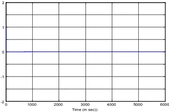
[image:3.595.57.297.363.749.2]18 Figure 4: The error in velocity (circular)
Figure 5: The error in azimuth (circular)
Figure 6: circular trajectory tracking
2) A square trajectory.
Figure 7 shows the error in azimuth and Figure8 shows the error in velocity . Figure 9 shows the desired and actual square trajectory.
Figure 7: The error in velocity(square)
Figure 8: The error in azimuth (square)
Figure 9: square trajectory tracking
7.
CONCLUSION
Fuzzy tuned PSO optimized PID control scheme is proposed for trajectory tracking problem for mobile robot . The particle swarm optimization method is used offline for the optimization of the parameters of PID controllers and fuzzy system is used for online fine tuning of these parameters. The online tuning property of the proposed control scheme solve the problems of disturbance , different load conditions and system parameters variations . Results show good tracking performance .
8.
REFERENCES
[1] G. Mester, "Intelligent Mobile Robot Motion Control in Unstructured Environments," Acta Polytechnica Hungarica ,Vol.07, No.04, 2010.
[2] Y. Wang, S. Wang, R. Tan and Y. Jiang,"Motion control of a wheeled mobile robot using digital acceleration control method", International Journal of Innovative Computing, Information and Control, Vol.09, No.01, pp.387-396, 2013.
[3] H. Ouarda, "Novel Mobile Robot Path planning Algorithm", International Journal of system applications, engineering and development, Vol.04, No.04, 2010.
[4] T. Lee, K. Song ,C. Lee and C. Teng, “Tracking Control of Mobile Robots Using Saturation Feedback Controller”, IEEE Transactions on control system technology , Vol.09, No.2, Taiwan, March 2001.
[5] P. Lahoty and G. Parmar, "A Comparative Study of Tuning of PID Controller using Evolutionary Algorithms", International Journal of Emerging Technology and Advanced Engineering, Vol.03, No.01, 2013.
[6] M. I. Hamzah and Turki Y Abdalla, “ Mobile Robot Navigation using Fuzzy Logic and Wavelet Network” , International Journal of Robotics and Automation, Vol. 3, Nol. 3, 2014.
-04 0 04 0.8 1.2 1.6 2
-04 0 0.4 0.8 12
1.6 2
X (m) Y (m)
Actual p Desired 0 1000 2000 3000 4000 5000 6000 -2
-1 0 0.5
1 2
Time (m sec)
0 1000 2000 3000 4000 5000 6000 -2
-1 0 1 2
Time (m sec))
--1 -075 -0.5 -0.25 0 0.25 0.5 0.75 1 0
025 0.5 075 1.25 1.75
X (m) Actual Desired 2
1.5
1 Y (m)
0 1000 2000 3000 4000 5000 6000 -2
-1 0 1 2
Time (m sec)
0 1000 2000 3000 4000 5000 6000 -2
-1 0 1 2
[image:4.595.93.234.342.469.2] [image:4.595.87.252.561.670.2][7] M. A. Abido, “Optimal design of power-system stabilizers using particleswarm optimization,” IEEE Trans. Energy Conversion, vol. 17, pp.406-413, Sep. 2002.
[8] D. R. Shircliff, "Build A Remote-Controlled Robot", eBook, Copyright © by The McGraw-Hill Companies, 2002.
[9] G. Mester, "Obstacle Avoidance of Mobile Robots in Unknown Environments", SISY, International Symposium on Intelligent Systems and Informatics 24-25 Subotica, Serbia, August, 2007.
[10] A. Albagul and Wahyudi, "Dynamic Modelling and Adaptive Traction Control for Mobile Robots", 30th Annual Conference of the IEEE Industrial Electronics Society, November 2 - 6, Susan, Korea 2004.
[11] J. Kennedy and R. Eberhart, “Particle swarm optimization,” in Proc.IEEE Int. Conf. Neural Networks , vol. IV, Perth, Australia, 1995,pp.1942–1948.
[12] Z.-L. Gaing, “A particle swarm optimization approach for optimum design of PID controller in AVR system,” IEEE Trans. EnergyConversion, vol. 19, pp. 384-391, June 2004.
[13] H. Yoshida, K. Kawata, Y. Fukuyama, S. Takayama, and Y. Nakanishi, “A particle swarm optimization for reactive power and voltage control considering voltage security assessment,” IEEE Trans. on Power Systems, Vol. 15, No. 4, Nov.
[14] AA Ahmed, TY Abdalla, AA Abed, “Path planning of mobile robot by using modified optimized potential field method” Iinternational journal of computer applications,vol. 113, No.4, 2015.
[15] TY Abdalla, AA Abed, AA Ahmed, “Mobile robot navigation using PSO-optimized fuzzy artificial potential field with fuzzy control” Journal of Intelligent & Fuzzy Systems,vol. 32, No.6,. 2017.
[16] TY Abdalla, HA Hairik, AM Dakhil , “Minimization of torque ripple in DTC of induction motor using fuzzy mode duty cycle controller ”, Energy, Power and Control (EPC-IQ), 1st International Conference on, IEEE 2010.
[17] Z.T. Allawi and Turki Y. Abdalla "An Optimal Defuzzification Method for Interval Type-2 Fuzzy Logic Control Scheme" IEEE science and information conference , 2015, London
[18] A. Kaur, A. Kaur, "Comparison of Mamdani-Type and Sugeno-Type Fuzzy Inference Systems for Air Conditioning System", International Journal of Soft Computing and Engineering (IJSCE), Vol.02, 2012
[19] Y. Yang, W. Wang, D. J. Yu and G. Ding, "A fuzzy parameters adaptive PID controller design of digital positional servo system", IEEE Proceeding of the First International Conference on Machine Learning and Cybernetics., pp. 310–314, 2002 ,china.
[20] W H Almutar, " Fuzzy Control Schemes for Active Suspension System" M Sc. thesis, university of Basrah, 2015.