© 2019, IRJET | Impact Factor value: 7.211 | ISO 9001:2008 Certified Journal | Page 694
Study on Cable Stayed Bridge using CSiBridge Software
Dr. Laju Kottalil
1, M Merin Sabu
2, Maria S Mathew
2, Megha Pavanan
2, Swaleeh Ali Ramzan V K
21
Prof, Department of Civil Engineering, Mar Athanasius College of Engineering, Kothamangalam, Kerala, India
2
Student, Department of Civil Engineering, Mar Athanasius College of Engineering, Kothamangalam, Kerala, India
---***---Abstract -
Cable-stayed bridges have emerged as thedominant structural system for long span bridge crossings during the past thirty years. This success is due to a combination of technical advancements and pleasing aesthetics attributes. The interaction of the various structural components results in an efficient structure which is continuously evolving and providing new methods to increase span lengths. The objective of this project is to conduct a parametric study on the behaviour of bridges under loading conditions. The results were compared and evaluated in terms of allowable displacement and bending moment. Out of various softwares, CSi bridge software is used due to its advanced modeling features and highly sophisticated design.
Key Words: Cable Stayed Bridge, CSi Bridge Software, Parametric Study, Analysis, Modelling
1. INTRODUCTION
Bridges may be classified by how the actions of tension, compression, bending, torsion and shear are distributed through their structure. Cable stayed bridges are one of a kind. Structural analysis can evaluate whether a specific structural design will be able to withstand external and internal stresses and forces expected for the design.
1.1 Cable stayed bridge
Cable stayed bridges are one of the most used bridge typologies for spans between 200 m to about 1100m due to their structural efficiency, cost and aesthetics. The major factors that contributed to the development of cable stayed bridges were the introduction of high strength steels, orthotropic type decks, development of welding techniques
and progress in structural analysis. Cable stayed bridge consists of a deck supported by a set of
stay cables connecting it to one or more towers; this geometry combined with high strength materials used in its construction results in very slender and flexible structures that are very sensitive to traffic, wind and seismic loads .It is a structural system with a continuous girder supported by inclined stay cables from the towers. From the mechanical point of view, the cable-stayed bridge is a continuous girder bridge supported by elastic supports .The main cable is eliminated and the cables are connected directly from the deck to the tower. This way, all steel cables are in tension and are used to their full efficiency. Due to the direct connection of cables to the pylon, all forces acting on the
members are axial. The steel cable is stretched straight between the pylon and the deck which means it is subjected to axial tension, and the pylon has half of the total load acting on either side of it which means the resulting force is direct compression. The structural components of a cable-stayed system behave in the following manner: The stiffening girder transmits the load to the tower through the cables, which are always in tension. The stiffening girder is subjected to bending and axial loading. The tower transmits the load to the foundation under mainly axial action.
The cable-stayed bridge has spanning capacity longer than that of cantilever bridges, truss bridges, arch bridges, and box girder bridges, but shorter than that of suspension bridges. In this range, the cable-stayed bridge is very economical and has elegant appearance due to the relatively small girder depth and has proved to be very competitive against other bridge types. The bending moment in cable stayed bridge is very less, due to the direct forces. This reduces the amount of steel and concrete required by a large scale, making the bridge more efficient and more economic than the suspension bridge by reducing the cost of maintenance. With the reduced bending moments, the width of deck can also be reduced. It has much greater stiffness than the suspension bridge, so that deformations of the deck under live loads are reduced. They can be constructed by cantilevering out from the tower – the cables act both as temporary and permanent supports to the bridge deck. For a symmetrical bridge (i.e. spans on either side of the tower are the same), the horizontal forces balance and large ground anchorages are not required.
1.2 CSiBridge Software
© 2019, IRJET | Impact Factor value: 7.211 | ISO 9001:2008 Certified Journal | Page 695
tailored for the engineering of bridge systems. Suspension,cable-stay, elevated-roadway, and other types of bridge systems may be modeled and designed to suit any one of a variety of purposes, including means for crossing water, linking points between shear terrain, or extending over highway infrastructure. Customized controls and features integrate across a powerful object-based modeling environment to offer an intuitive, practical, and productive computational tool for bridge engineering. Advanced modeling features and sophisticated analysis techniques account for dynamic effects, inelastic behavior, and geometric nonlinearity. It implements a parametric object-based modeling approach when developing analytical bridge systems. This enables designers to assign bridge composition as an assembly of objects; ie, roadway superstructure, substructure, abutments, piers, foundation system, etc. CSiBridge is the premier software for bridge engineering.
The major steps involved in the modelling process include: Create the Layout Line(s):Layout lines are reference lines used for defining the horizontal and vertical alignment of the bridge and the vehicle lanes. Layout lines are defined using stations for distance, bearings for horizontal alignment, and grades for vertical alignment. Layout lines may be straight, bent or curved, both horizontally and vertically.
Define lanes on the bridge: Lanes must be defined before a bridge model can be analyzed for vehicle live loads. Lanes are used in the definition of bridge live type load patterns that are used in static and dynamic multi-step load cases. Lanes can be defined with reference to layout lines or existing frame objects. Typically, when using the bridge modeler, lanes should be defined from layout lines.
Define Superstructure components:These component definitions include deck section, diaphragms and parametric variations. The deck section definition includes the section property, material property, the slab and girder thicknesses etc. Various precast girders are available which can be modeled to our requirement and rigid links have been used to join the disconnected beams together. The software also allows us to prestress the beams to the required compression. Parametric variations define variations in the deck section along the length of the bridge. Almost all parameters used in the parametric definition of a deck section can be specified to vary. The variations may be linear, parabolic or circular. After a variation has been defined, it can be assigned as part of the deck section
depending upon soil condition, design load etc. Here we have considered steel pylons of pipe section. There are also different boundary conditions prevailing for the connection and this study involves fixed condition.
Define vehicle loads :In CSiBridge, vehicles must be defined to analyze a bridge model for vehicle loads. Those vehicle loads are applied to the structure through lanes. In addition, vehicles classes must be defined to analyze a bridge model for vehicle live loads using a moving load load case. Numerous standard vehicle types are built into the program. In addition, the General Vehicle feature allows creation of customized vehicle definitions. Each vehicle definition consists of one or more concentrated or uniform loads.
Define load patterns: A load pattern is a specified spatial distribution of forces, displacements, temperatures, and other effects that act upon the bridge. A load pattern by itself does not cause any response in the bridge. Load patterns must be applied in load cases in order to produce results. One special type of load pattern available in CSiBridge is the Bridge Live Load pattern. In that type of load pattern, one or more vehicles that move across the bridge can be specified. For each vehicle, the following can be specified: a time that the vehicle starts loading the bridge, the initial vehicle location, and the direction of travel and the speed of the vehicle. When used in a multi-step static or multi-step dynamic (direct integration time history) load case, this type of load pattern is useful in evaluating special vehicle loads.
© 2019, IRJET | Impact Factor value: 7.211 | ISO 9001:2008 Certified Journal | Page 696
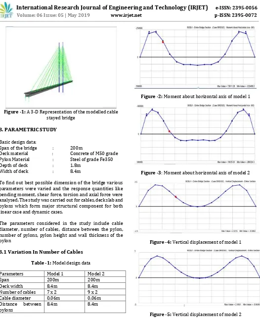
Figure -1: A 3-D Representation of the modelled cablestayed bridge
3. PARAMETRIC STUDY
Basic design data:
Span of the bridge : 200m
Deck material : Concrete of M50 grade Pylon Material : Steel of grade Fe350
Depth of deck : 1.8m
Width of deck : 8.4m
To find out best possible dimension of the bridge various parameters were varied and the response quantities like bending moment, shear force, torsion and axial force were analysed. The study was carried out for cables, deck slab and pylons which form major structural component for both linear case and dynamic cases.
The parameters considered in the study include cable diameter, number of cables, distance between the pylon, number of pylons, pylon height and wall thickness of the pylon
3.1 Variation In Number of Cables
Table -1: Model design data
Parameters Model 1 Model 2
Span 200m 200m
Deck width 8.4m 8.4m
Number of cables 7 x 2 9 x 2
Cable diameter 0.06m 0.06m
Distance between
pylons 8.4m 8.4m
Figure -2: Moment about horizontal axis of model 1
Figure -3: Moment about horizontal axis of model 2
[image:3.595.38.564.40.690.2]Figure -4: Vertical displacement of model 1
© 2019, IRJET | Impact Factor value: 7.211 | ISO 9001:2008 Certified Journal | Page 697
kNmModel 2 9 X 2 73611.28
kNm 2.3315 m
3.2 Variation in cable diameter
Table -3: Model design data
Parameters Model 1 Model2
Span 200m 200m
Deck width 8.4m 8.4m
Number of cables 9 x 2 9 x 2
Cable diameter 0.04m 0.06m
Distance between
pylons 8.4m 8.4m
Figure -6: Moment about horizontal axis of model 1
Figure -7: Moment about horizontal axis of model 2
Figure -8: Vertical displacement of model 1
Figure -9: Vertical displacement of model 2
Table -4: Result comparison
Cable
diameter Maximum moment about horizontal axis
Maximum vertical displacement
Model
1 0.04 m 74325.53 kNm 2.5951 m Model
2 0.06 m 66893.53 kNm 1.7267 m
3.3 Variation in distance between the pylons
Table -5: Model design data
Parameters Model 1 Model 2
Sspan 200m 200m
Deck width 8.4m 8.4m
Number of cables 9 x 2 9 x 2
Cable diameter 0.04m 0.04m
Distance between
pylons 8.4m 12m
Figure -10: Moment about horizontal axis of model 1
© 2019, IRJET | Impact Factor value: 7.211 | ISO 9001:2008 Certified Journal | Page 698
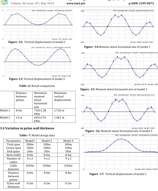
Figure -12: Vertical displacement of model 1 [image:5.595.36.572.60.706.2]Figure-13: Vertical displacement of model 2
Table -6: Result comparison
Distance between pylons
Maximum moment about horizontal axis
Maximum vertical displacement
Model 1 8.4m 73611.28
kNm 1.726 m
Model 2 12 m 64513.76
kNm 1.461 m
[image:5.595.49.571.371.702.2]3.4 Variation in pylon wall thickness
Table -7: Model design data
Figure -14:Moment about horizontal axis of model 1
Figure -15: Moment about horizontal axis of model 2
Figure -16: Moment about horizontal axis of model 3
Figure -17: Vertical displacement of model 1 Parameters Model1 Model 2 Model 3
Total span Centre span
End spans
200m 100m 50m
200m 100m 50m
200m 100m 50m
Deck width 8.4m 8.4m 8.4m
Number of
cables 9 x 2 9 x 2 9 x 2
Cable
diameter 0.04m 0.04m 0.04m
Distance between pylons
8.4m 8.4m 8.4m
Pylon wall
© 2019, IRJET | Impact Factor value: 7.211 | ISO 9001:2008 Certified Journal | Page 699
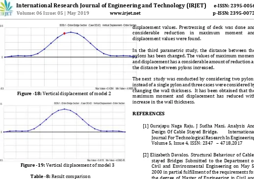
Figure -18: Vertical displacement of model 2 [image:6.595.38.556.44.409.2]Figure -19: Vertical displacement of model 3
Table -8: Result comparison
Pylon wall
thickness Maximum moment about horizontal axis
Maximum vertical displacement Model 1 0.3m 23856.264kNm 0.4233 m Model 2 0.2m 23977.873 kNm 0.4264 m Model 3 0.1m 24225.28 kNm 0.4318 m
Bending moment and displacement value was found to be decreasing with reduction in number of cables. Moment and vertical displacement found to be decreasing as the diameter of cables decreased. Values for maximum moment and displacement had a considerable amount of reduction as the distance between two pylons increased. Moment and vertical displacement found to be decreasing as the pylon wall thickness increased.
4. CONCLUSIONS
Considering the first parametric study wherein the number of cables have been changed, it is seen that the maximum moment and displacement has decreased while increasing the number of cables.
In the second parametric study, the cable diameters have been changed. Moment and displacement was found to be decreasing as the cable diameters increases.
Thus, it has been concluded that prestressing the deck and pretensioning the cables will reduce the moment and
The next study was conducted by considering two pylons instead of a single pylon and three cases were considered by changing the wall thickness. It has been obtained that the maximum moment and displacement has reduced with increase in the wall thickness.
REFERENCES
[1]Gurajapu Naga Raju, J Sudha Mani. Analysis And Design Of Cable Stayed Bridge. International Journal For Technological Research In Engineering Volume 5, Issue 4, ISSN: 2347 – 4718,2017
[2]Elizabeth Davalos. Structural Behaviour of Cable-stayed Bridges Submitted to the Department of Civil and Environmental Engineering on May 5, 2000 in partial fulfillment of the requirements for the degree of Master of Engineering in Civil and Environmental Engineering.
[3]Lin W & Yoda T, Text Book on Cable-Stayed Bridges. Bridge Engineering, 175–194, 2017
[4]Krishna Raju N, ‘Design Of Bridges’, Oxford & IBH publishing co. pvt. Ltd., ISBN 81-204-0344-4
[5]Umang A. Koyani, Kaushik C. Koradia, ‘Parametric
Study Of Cable StayedBridge’ Journal of Emerging
Technologies and Innovative Research (JETIR) , ISSN-2349-5162
[6]T. P. Agrawal, ‘Cable Stayed Bridges-Parametric
Study’, Journal Of bridge Engineering, ASCE, ISSN