http://www.scirp.org/journal/jcc ISSN Online: 2327-5227
ISSN Print: 2327-5219
DOI: 10.4236/jcc.2018.64002 Apr. 24, 2018 31 Journal of Computer and Communications
Theoretical Investigation of Convergence of
Max-SINR Algorithm in the MIMO Interference
Network
Ali Dalir, Hassan Aghaeinia
Department of Electrical Engineering, Amirkabir University of Technology (Tehran Polytechnic), Tehran, Iran
Abstract
Design of transceiver for interference channel (IC) is an important research area. Max-SINR algorithm is an iterative algorithm for multi-input mul-ti-output (MIMO) IC. Nodes in the MIMO IC, work in a time division duplex mode, where half of them are equipped with M antennas while the others have
N antennas. It is shown how the Max-SINR algorithm proposed by Gomadam
et al. converges by considering an equivalent problem, i.e. a constrained maximization problem.
Keywords
Converge, Interference Channel, MIMO, Max-SINR
1. Introduction
To date, different approaches have been developed to address interference man-agement. Beside the conventional methods for interference management [1], a new method termed “interference alignment” (IA) has been proposed by the re-searchers. The basic idea behind the IA is to fit undesirable signals into a small portion of the signal space, observed by each receiver (interference subspace), and then leave the remaining signal space free of any interference for the desired signal (signal subspace). In [1]-[12], and [13], the authors implement the IA for different scenarios.
Transceiver for multi-input multi-output (MIMO) interference channel (IC) has been designed by progressive minimization of the leakage interference, Al-gorithm 1 in [4]. In this scheme, the IA is achieved only at very high SNRs. The Max-SINR algorithm, Algorithm 2 in [4], is another approach to obtain IA. This technique shows significant improvements in terms of sum rate in the range of How to cite this paper: Dalir, A. and
Ag-haeinia, H. (2018) Theoretical Investigation of Convergence of Max-SINR Algorithm in the MIMO Interference Network. Journal of Computer and Communications, 6, 31-37. https://doi.org/10.4236/jcc.2018.64002
Received: March 2, 2018 Accepted: April 21, 2018 Published: April 24, 2018
Copyright © 2018 by authors and Scientific Research Publishing Inc. This work is licensed under the Creative Commons Attribution International License (CC BY 4.0).
http://creativecommons.org/licenses/by/4.0/
DOI: 10.4236/jcc.2018.64002 32 Journal of Computer and Communications low-to-intermediate SNRs and achieves the IA at high SNR.
The algorithm 1 seeks perfect interference alignment. In particular, it seeks to create an interference-free subspace of the required number of dimensions that is designated as the desired signal subspace. However, Algorithm 1 makes no at-tempt to maximize the desired signal power within the desired signal subspace. In fact, Algorithm 1 does not depend at all on the direct channels through which the desired signal arrives at the intended receiver. Therefore, while the interfe-rence is eliminated within the desired space, no coherent combining gain (array gain) for the desired signal is obtained with Algorithm 1. While this is optimal as all signal powers approach infinity, it is not optimal in general at intermediate SNR values. Therefore, Algorithm 2 may be designed which will perform better than Algorithm 1 at intermediate SNR values.
Authors show that Algorithm 1 converges and convergence of Max-SINR is not presented. Since all the iterative algorithms have meaning when converges. No convergence proof has been presented in literature for Max SINR algorithm. In this paper, convergence issue of Max-SINR is investigated. It is shown how the Max-SINR algorithm proposed by Gomadam et al. converges by considering an equivalent problem, i.e. a constrained maximization problem.
Convergence of robust MMSE is shown in [14] theoretically. Total fraction of interference leakage to received signal parameter is used to show convergence numerically. To validate the correctness of the proposed proof, numerical con-vergence behavior of the Max SINR is compared with robust MMSE.
2. System Model
In a K-user MIMO IC, transmitter j and receiver k have M and N antennas, re-spectively. Independent symbols j
D with power P are sent by the jth
transmit-ter. Channel matrices between transmitter j and receiver k is denoted by kj
H .
The received signal at receiver k is expressed by
1
K
k kj j k
j
Y H X Z
=
=
∑
+ (1)where j
X is the M×1 signal vector transmitted by the transmitter j and
(
0)
~ 0,
k
Z CN N I is additive white Gaussian noise (AWGN) vector.
Beam-forming strategy is used based on the interference alignment. In particular, transmitter j precodes symbol vector by using the precoder matrix. j
V is the
j
M×D precoder matrix. Columns of Vj, j d
v , are unit norm vectors. Receiver
k estimates the transmitted symbol vector k
s by using the interference
suppres-sion matrix k
U . The received signal is filtered by Uk as Yk =U Yk† k.
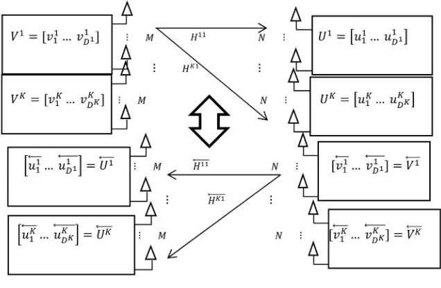
Each node works in a time division duplex (TDD) mode. At two consecutive time slots, first, nodes on the left-hand side send the data to the nodes on the right-hand side. Then the role of nodes is switched and the nodes on the left-hand side receive the data, as illustrated in Figure 1.
The relation between the original and reciprocal channel matrices is
†
jk kj
H =H
DOI: 10.4236/jcc.2018.64002 33 Journal of Computer and Communications
Figure 1. System model.
original network’s transmitters and vice versa, then Vk =Uk and Uj=Vj.
According to the system model, the SINR value for the dth data stream at kth receiver is expressed by (where, . denotes the Euclidian norm.)
†
† †
2
2 2 2
0
1 1
j
k kk k
d d
k d
K D k kj j k kk k k
d m d d d
j m
P u H v SINR
P = = u H v P u H v N u
=
− +
∑ ∑
(2)Alternatively k
d
SINR can be expressed by
†
†
0
k k k
k d d d
d k k k k
d d d
u T u SINR
u S T N I u
=
− +
(3)
where † †
1 1
j
K D
k kj j j kj
m m
j m
S =P
∑ ∑
= = H v v H and k kk k k† kk†d d d
T =PH v v H denote,
re-spectively, the covariance matrix of all data streams observed by the receiver k
and covariance matrix of the dth desirable data stream.
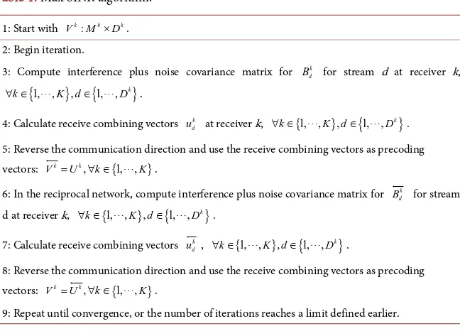
3. Proof of Convergence of Max-SINR Algorithm
Max-SINR algorithm is presented in algorithm 2 in [4]. It is repeated in Table 1. Maximizing (3) over k
d
u can be written as follow
†
†
max
k k
d d
k k
d d
u Gu
u Fu (4)
where matrices are †
0
k d
G=G =T ≥ , and F=F† =Sk−Tdk+N I0 >0. It is
shown in [15] that the optimization problem in (4) is equivalent to †
† ,
s.t max
. 1.
k k
d d
k k
d d
u Gu
u Fu =
(5)
For the equivalent problem, i.e. constrained maximization in (5),
Lagran-gian function is
(
)
†(
†)
, 1
k k k k k
d d d d d
DOI: 10.4236/jcc.2018.64002 34 Journal of Computer and Communications
Table 1. Max SINR algorithm.
1: Start with k: k k
V M ×D .
2: Begin iteration.
3: Compute interference plus noise covariance matrix for k d
B for stream d at receiver k,
{
1, ,}
,{
1, , k}
k K d D
∀ ∈ ∈ .
4: Calculate receive combining vectors k d
u at receiver k, {1, , },
{
1, , k}
k K d D
∀ ∈ ∈ .
5: Reverse the communication direction and use the receive combining vectors as precoding vectors: k k, {1, , }
V =U ∀ ∈k K .
6: In the reciprocal network, compute interference plus noise covariance matrix for k d
B
for stream d at receiver k, {1, , },
{
1, , k}
k K d D
∀ ∈ ∈ .
7: Calculate receive combining vectors k d
u, {1, , },
{
1, , k}
k K d D
∀ ∈ ∈ .
8: Reverse the communication direction and use the receive combining vectors as precoding vectors: k k, {1, , }
V =U∀ ∈k K .
9: Repeat until convergence, or the number of iterations reaches a limit defined earlier.
(
,)
0 k d k d l u u λ ∂ =∂ and
(
,)
0
k d
l u λ
λ ∂
=
∂ . The solution is denoted by *
k d
u and Lagrange
multiplier by λ*. It is also shown in [15] that k*
d
u is the eigenvector
corres-ponding to the maximal eigenvalue of 1
F G− and λ* is k*† k*
d d
u Gu .
Therefore, the unit vector that maximizes (3), is given by
1
k d
u = ϑF G− (6)
where operator ϑ
[ ]
. denotes the eigenvector corresponding to the maximalei-genvalue of a matrix.
The convergence of the algorithm is proved by considering total Lagrangian function of all data streams in the network 1 1
(
,)
j
K D k
d k= d=l u λ
∑ ∑
. The metric isde-fined in (7). The function is unchanged in the original and reciprocal networks since the transmit and receive filters change their roles. Therefore, each step [4, Algorithm 2] in the algorithm increases the value of the function. This implies that the algorithm converges.
(
)
1 1 and and max , j j KK D k
d
k d
V U
j k
metric = =l u λ
∀ ∈ =
∑ ∑
(7) Accordingly:(
)
1 1max K jmax k ,
d
K D k
d
k d
U u
k
metric = = l u λ
∀ ∈
=
∑ ∑
(8)
In other words, given Vj∀ ∈j , Step 4 [4, Algorithm 2] increases the value
of (7) over all possible choices of k
U ∀ ∈k . The filter Uj computed in Step 7
[4, Algorithm 2], based on Vk =Uk, also maximizes the metric in the reciprocal
channel (9).
( )
† †1 1 1 1
max j K Dj j, K Dj j j 1 j j
d d d d d
j d j d
U j
metric = =l u λ = =u Gu λ u F u
DOI: 10.4236/jcc.2018.64002 35 Journal of Computer and Communications Since Vk =Uk and Uj=Vj, the metric remains unchanged in the original
and reciprocal networks, according to following equation:
(
)
† †
† † †
0
1 1 1 1
1 1 1 1
1
j j
j j
K D j j j K D j j j j
d d d d d d d
j d j d
K D K D j k kj j j kj k
d m d d m
j d k m
metric u T u u T N I u P u H v v H u metric
λ
λ
= = = =
= = = =
= + + −
− =
∑ ∑
∑ ∑
∑ ∑ ∑ ∑
(10)
Therefore, Step 7 [4, Algorithm 2] also can increase the value of (7). Since the value of (7) is monotonically increased after every iteration, convergence of the algorithm is guaranteed.
4. Simulation Results
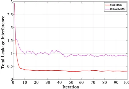
Simulation results to validate the correctness of the proposed proof are based on fraction of interference leakage to the received signal parameter [14]. Figure 2
[image:5.595.266.478.332.477.2]and Figure 3 show total fraction of interference leakage to received signal. Since convergence of robust MMSE is shown in [14], its total parameter is plotted in
Figure 2 and Figure 3 as well. Convergence behavior of the algorithm in com-parison with robust MMSE implies a convergent scheme.
Figure 2. Sum of fraction of interference leakage to received signal at each user.
3
M =N= , D=1, K=4 interference network with 2 0.1 σ = , and
0 10 dB
P
[image:5.595.260.498.502.680.2]N = .
Figure 3.Sum of fraction of interference leakage to received signal at each user. M =3, 4
N= , D=2, K=2 interference network with 2 0.1 σ = , and
0 10 dB
P
DOI: 10.4236/jcc.2018.64002 36 Journal of Computer and Communications
References
[1] Jafar, S. and Fakhereddin, M. (2007) Degrees of Freedom for the MIMO Interfe-rence Channel. IEEE Transactions on Information Theory, 53, 2637-2642.
https://doi.org/10.1109/TIT.2007.899557
[2] Gou, T. and Jafar, S.A. (2010) Degrees of Freedom of the K User M × N MIMO In-terference Channel. IEEE Transactions on Information Theory, 56, 6040-6057.
https://doi.org/10.1109/TIT.2010.2080830
[3] Cadambe, V. and Jafar, S.A. (2008) Interference Alignment and the Degrees of Freedom of the K User Interference Channel. IEEE Transactions on Information Theory, 54, 3425-3441. https://doi.org/10.1109/TIT.2008.926344
[4] Gomadam, K., Cadambe, V.R. and Jafar, S.A. (2011) A Distributed Numerical Ap-proach to Interference Alignment and Applications to Wireless Interference Net-works. IEEE Transactions on Information Theory, 57, 3309-3322.
https://doi.org/10.1109/TIT.2011.2142270
[5] Zhu, B., Ge, J., Li, J. and Sun, C. (2012) Subspace Optimization-Based Iterative In-terference Alignment Algorithm on the Grassmann Manifold. IET Communica-tions, 6, 3084-3090. https://doi.org/10.1049/iet-com.2012.0467
[6] Yu, H. and Sung, Y. (2010) Least Squares Approach to Joint Beam Design for Inter-ference Alignment in Multiuser Multi-Input Multi-Output InterInter-ference Channels.
IEEE Transactions on Signal Processing, 58, 4960-4966.
https://doi.org/10.1109/TSP.2010.2051155
[7] Papailiopoulos, D.S. and Dimakis, A.G. (2012) Interference Alignment as a Rank Constrained Rank Minimization. IEEE Transactions on Signal Processing, 60, 4278-4288. https://doi.org/10.1109/TSP.2012.2197393
[8] Du, H., Ratnarajah, T., Sellathurai, M. and Papadias, C.B. (2013) Reweighted Nuc-lear Norm Approach for Interference Alignment. IEEE Transactions on Communi-cations, 61, 3754-3765. https://doi.org/10.1109/TCOMM.2013.071813.130065
[9] Kumar, K.R. and Xue, F. (2010) An Iterative Algorithm for Joint Signal and Interfe-rence Alignment. 2010 IEEE International Symposium on Information Theory Proceedings (ISIT), 13-18 June 2010, Austin, TX, 2293-2297.
https://doi.org/10.1109/ISIT.2010.5513646
[10] Schmidt, D.A., Shi, C., Berry, R.A., Honig, M.L. and Utschick, W. (2009) Minimum Mean Squared Error Interference Alignment. 2009 Conference Record of the 43
Asilomar Conference on Signals, Systems and Computers,1-4 November 2009, Pa-cific Grove, CA, 1106-1110. https://doi.org/10.1109/ACSSC.2009.5470055
[11] Santamaria, I., Gonzalez, O., Heath, R.W. and Peters, S.W. (2010) Maximum Sum-Rate Interference Alignment Algorithms for MIMO Channels. 2010 IEEE Global Telecommunications Conference (GLOBECOM 2010), 6-10 December 2010, Miami, FL, 1-6. https://doi.org/10.1109/GLOCOM.2010.5683919
[12] Gao, H., Leithon, J., Yuen, C. and Suraweera, H.A. (2013) New Uplink Opportunis-tic Interference Alignment: An Active Alignment Approach.2013 IEEE Wireless Communications and Networking Conference (WCNC), 7-10 April 2013, Shanghai, 3099-3104. https://doi.org/10.1109/WCNC.2013.6555057
[13] Peters, S.W. and Heath Jr., R.W. (2009) Interference Alignment via Alternating Mi-nimization. 2009 IEEE International Conference on Acoustics, Speech and Signal Processing (ICASSP 2009), 19-24 April 2009, Taipei, 2445-2448.
DOI: 10.4236/jcc.2018.64002 37 Journal of Computer and Communications
[14] Shen, H., Li, B., Tao, M. and Luo, Y. (2010) The New Interference Alignment Scheme for the MIMO Interference Channel. 2010 IEEE Wireless Communications and Networking Conference (WCNC), 18-21 April 2010, Sydney.
https://doi.org/10.1109/WCNC.2010.5506770