an engine.
Keywords—Pressure wave supercharger, CFD, PWS, Diesel Engine, Temperature, pressure, Velocity, Modifications
1. INTRODUCTION
The first Internal combustion engine was developed in mid 19th century. They were used for transportation applications. Since them, engineers and scientists have been constantly working on improvement of the engine's design, performance, efficiency, size, emissions, conservation of energy etc. This led to the development of the turbochargers and superchargers. The second World war and need of power for military movements accelerated the development of the charging technology. Turbochargers were used in war planes. Turbocharger helped increase the performance of the engine, but due to the presence of turbine as its component, it increased the weight of the engine and complicated further development practices. Scientists noticed that wave rotor performs both expansion and compression in the same chamber, thus reducing the space required. Thus, began the development of wave rotor technologies for charging of engine. One such is Pressure wave Supercharger. But this technology has its fair share of disadvantages- sealing of components, intermingling of exhaust gases and fresh air, studying complex non-steady flow phenomenon etc. This hampered the development of the technology for a long time. During the last decade, continuous progress has been made in solving the complex flow of fluid in wave rotor by implementing new technologies and ideas.
2. WORKING PRINCIPLE
The pressure wave supercharger utilizes the concept of change in pressure due to temperature gradient. The supercharger consists of a hot endwall, a cold endwall and a rotor enclosed in a rotor shroud. The rotor consists of a number of channels that allows the inlet and outlet flow of gases. The fresh air enters from the air inlet port (AI) in cold endwall and moves toward the rotor. The exhaust gas from the diesel engine enters through the exhaust inlet port (EI) in the hot endwall and moves towards the rotor. Since the rotor is a rotating component, mixing of fresh air and exhaust gases takes place and much of the air is drafted through to air outlet (AO) port in the cold endwall that is connected to the engine. The remaining mixture of gases is transferred to the atmosphere through the exhaust air outlet (EO) in hot endwall. Due to emission of exhaust gases from engine, the temperature of the exhaust gas is higher than fresh air. Thus, it contributes to keeping the temperature of the hot endwall higher than that of cold endwall. The rotation of the rotor causes the rapid mixture of fresh air and exhaust air. This results in energy transfer in such short time that the supercharger can respond quickly to the engine. This emits the issue of 'turbo-lag', which is often found in turbochargers. This also results in large torque at small engine speeds, which makes it suitable for engines where loads vary a lot.
3. DESIGN
Fig.1- PWS Element Rotor
Table 1- Engine Specifications
hot endwall much higher than that of cold endwall. The rotor consists of a number of channels through which the exhaust air and fresh air would intermingle and eventually pass each other. The outside diameter of the rotor is estimated to be 214 mm and the length of the assembly to be 540mm. The rotation of the rotor will cause the mixture to flow towards the low pressure area. Thus, the mixture will flow towards air outlet(AO) port and through to the engine. Meanwhile, the excess air present in the rotor, will flow towards the exhaust outlet(EO) port and through to the atmosphere. The rotor is enclosed inside rotor shroud, which protects the rotor blades from the environment. This shroud is provided adequate clearance to ensure proper working of the rotor. One end of the shroud is bolted to the hot endwall while the other to the cold endwall. This change in temperature helps to create adequate pressure inside the rotor. The blades of the rotor are situated at equal angles from each other. In this case, there are 24 channels in the rotor, situated 15 degrees from each other. The number of channels present in the rotor have made the distinction between allocation of the device. The channels results in producing shock waves from exhaust gas that expands in the channels and compresses the intake fresh air. The volumetric flow rate of the supercharger was found to be 4.166m3/kg [(NDղv)/60]. Thus, area of outlet port was
calculated to be 0.0036 m2.
Fig. 2- Assembly of Pressure Wave Supercharger
Engine Type 4 stroke in-line diesel engine, Beinei Group Capacity Displacement 2.7 litres
Bore 93 mm
Stroke 102 mm
Cylinder Number 4
Compression ratio 17.5
Maximum power 60 kW(2500 rpm)
Maximum torque 235 Nm
Fuel Diesel
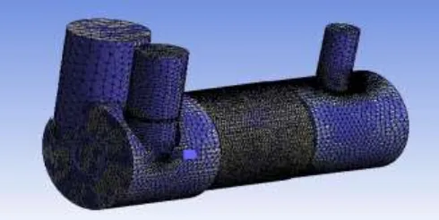
[image:2.596.164.422.628.740.2]the cold endwall, rotor and the hot endwall. The element size of the mesh is taken as 0.0419 m. the second step in meshing concerns the edge sizing since it contains a lot of edges. There are a total of 68 edges in the model . The element size for edge sizing is taken as 0.005 m. This results in a very fine mesh of the model.
[image:3.596.169.414.367.490.2]There is a separate rotating element in the model, the rotor which needs to be meshed differently. Hence, a meshing of the rotor is done having element size of 0.005 m. Now the extracted volume and the rotor have been meshed and then boundary conditions have to be set for the model. The type of meshing done on the model and the rotor is tetrahedral meshing. This kind of mesh contains 4 vertices, 6 edges, and is bounded by 4 triangular faces. The tetrahedral volume mesh is generated automatically.
Fig. 3-Meshing of the model
After applying the boundary conditions for the model or giving all the solutions for the meshed surfaces, the results can be viewed. For boundary conditions, air is selected to enter the inlets. It is assumed that there is no cavitation effect due to the flow of air. Although due to flow of gases at high pressure and temperature, the flow of the gases and air can be considered partially turbulent. The thermal characteristics of the model are selected to get temperature readings at the outlet. The rotor is given an angular speed of 35000 rpm approximately. The mass flow rate at the cold inlet is 5.104kg/s and the mass flow rate at the exhaust inlet is 7.656kg/s. These conditions are then applied and the results are then viewed.
(b)
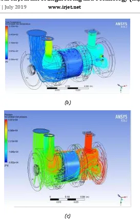
[image:4.596.166.439.58.485.2](c)
Fig. 4- The (a)velocity, (b)temperature and (c)pressure of model
5. RESULT AND CONCLUSION
The velocity of the model is analyzed and the average velocity of the air in the model is found to be 305 m/s approximately. The average temperature of the air in the model is estimated to be 316K and the average pressure of air at the outlet is estimated to be 77.115 kPa.
S.No Inlet Condition Outlet Condition 1 Cold inlet temperature Cold ouuletendwall
temperature
288 K 316 K
2 Exhaust inlet flow rate Cold wall outlet pressure
7.654 kg/sec 77.115 kPa
3 Cold inlet velocity Cold outlet velocity
The second modification carried out was to introduce a separator in the Air Inlet (AI) port. This would decrease the cross-section area of the port. It would hence lead to increase in pressure of the inlet fresh air, thus increasing the overall pressure of the supercharger.
The third modification carried out was to decrease the internal diameter of Air Outlet (AO)port. This would result in the decrease of the cross-sectional area of the port, increasing the pressure of the mixture of air escaping through the outlet port.
REFERENCES
[1]Jiří Navrátil, Miloš Polášek, Oldřich Vítek, Jan Macek, Pavel Baumruk “Simulation Of Supercharged And
Turbocharged Small Spark-Ignition Engine" ČVUT v Praze / Výzkumné centrum spal. motorů a automobilů Josefa Božka, Technická 4, 166 07 Praha 6.
[2]Gerard E. Welch , Scott M. Jones and Daniel E. Paxson “Wave Rotor-Enhanced Gas Turbine Engines” NASA
Technical Memorandum 106998 AIAA-95-2799
[3]IOP Conference Series: Materials Science and Engineering “Evolution Of The Pressure Wave Supercharger
Concept” Iuliana Costiuc and Anghel Chiru 2017 IOP Conf. Ser.: Mater. Sci. Eng. 252 012081
[4]Emiliano Pipitone, Stefano Beccari, Giuseppe Genchi “Supercharging the DoubleFueled Spark Ignition Engine:
Performance and Efficiency” Department of Industrial and Digital Innovation, University of Palermo, Viale delle Scienze, Palermo 90128, Italy, [DOI: 10.1115/1.4036514]
[5]Pezhmman Akbari, Razi Nilam, Norbert Mueller “Review of Wave Rotor Technology and its applications”
Department of Mechanocal Engineering, Purdue School of Engineering and technology, Indianapolis, [DOI: 10.1115/1.2204628]
[6]F.Weber, L.Guezella, C. Onder “Modelling of a pressure wave Supercharger including exhaust gas recirculation”
Proc Instn Mech Engrs Vol 216 Part D: J Automobile Engineering, D10801 IMechE 2002
[7]Y.Lei, D.S. Zhou, H.G. Zhang “Investigation on Performance of a compression- ignition engine with pressure wave