© 2016, IRJET | Impact Factor value: 4.45 | ISO 9001:2008 Certified Journal | Page 3001
“Experimental Validation & Testing of Brake Chamber Mounting
bracket”
Mr. Sagar B. Awate
1, Prof. Vidyasagar R. Bajaj
2,
Prof. Arun Bhosale
31 ME Student, Department of Mechanical Engineering, Alard College of Engineering & Management, Pune, India 2 HOD, Department of Mechanical Engineering, Alard College of Engineering & Management, Pune, India. 3 Assistant Professor, Department of Mechanical Engineering, Sinhgad Academy of Engineering, Pune, India. ---***---Abstract – Experimental validation & testing is one of
the important parts in design finalization. Now a days advances software’s are developed to virtually test & validate the design of component but still physical validation & testing is necessary in order to check reliability, maintainability, performance of the designed component. This paper is about, physical validation & testing of newly designed brake chamber mounting bracket. Brake chamber mounting bracket is a part of air brake system. It is mounted on rear axle of vehicle. Air chamber / spring brake actuator is mounted on the bracket so it’s called as “brake chamber mounting bracket or spring brake actuator mounting bracket”. Critical tests are identified for brake chamber mounting bracket such as endurance test, deflection measurement test, vibration test & natural frequency detection test. The detail procedure, setup & test methods are described in the paper.
Keywords: Endurance, Fatigue
1. INTRODUCTION
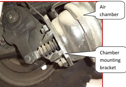
[image:1.595.308.573.231.363.2]Chamber mounting bracket is mounted on rear axle of vehicle at LH & RH side of the axle. The chamber mounting bracket is a part of air brake system mounted on axle. Bracket carries chamber of brake system, so is called as brake chamber mounting bracket. Below figure shows the assembly detail of chamber mounting bracket.
Figure 1 – Bracket fitment details.
1.1 Function of Chamber Mounting Bracket Chamber consist of reaction spring, diaphragm, push rod, air inlet & outlet connections. When brake gets operated by driver, high pressure air enters into air brake chamber. Air pressure gets applied on rubber diaphragm located inside the air brake chamber, which develops the force. Displacement of rubber diaphragm moves push rod in outward direction. Push rod is connected to auto slack adjuster as shown in below photographs.
Figure 2 – Bracket fitment on vehicle. LH side
bracket
RH side bracket
Air chamber
[image:1.595.310.574.556.737.2]© 2016, IRJET | Impact Factor value: 4.45 | ISO 9001:2008 Certified Journal | Page 3002 Auto slack adjuster is simply a lever which provides
leverage to the output force of chamber. One end of the auto slack adjuster is connected to “S” cam shaft of brake assembly. When push road moves in outward direction, which causes to rotate auto slack adjuster & while other end of auto slack adjuster, rotates the “S” cam shaft. “S” cam shaft moves brake liner against rotating drum. When stationary part (i.e. brake liner) pushed against rotating part (i.e. brake drum), this causes to induce reaction force in “S” cam shaft. Thus the reaction forces transferred to auto slack adjuster & then to chamber mounting bracket. Magnitude of the reaction force is equal to the applied force but opposite in direction. So chamber mounting bracket experiences the same force applied by air brake chamber but in opposite direction.
2. ENDURANCE / FATIGUE TEST.
Accelerated test methodology is used to validate the component. Today’s manufacturers face strong pressure to develop new, higher-technology products in record time, while improving productivity, product field reliability and overall quality. Estimating the failure-time distribution or long term performance of components of high-reliability products is particularly difficult. Most modern products are designed to operate without failure for years, decades or longer. Thus few units will fail or degrade appreciably in a test of practical length at normal use conditions. For example, the design and construction of a communications satellite may allow only eight months, to test components that are expected to be in service for 10 or 15 years. For such applications, Accelerated Tests (ATs) are used in manufacturing industries to assess or demonstrate component and subsystem reliability, to certify components, to detect failure modes so that they can be corrected, to compare different manufacturers, and so forth.
2.1 Reasons for Endurance / Fatigue test
In materials science, fatigue is the weakening of a material caused by repeatedly applied loads. It is the progressive and localized structural damage that occurs when a material is subjected to cyclic loading.
The nominal maximum stress values that cause such damage may be much less than the strength of the material typically quoted as the ultimate tensile stress limit, or the yield stress limit. Fatigue occurs when a material is subjected to repeat loading and unloading. If the loads are above a certain threshold, microscopic cracks will begin to form at the stress concentrators such as the surface, persistent slip bands (PSBs), and grain interfaces. Eventually a crack will reach a critical size, the crack will propagate suddenly, and the structure will fracture. The shape of the structure will significantly affect the fatigue life; square holes or sharp corners will lead to elevated local stresses where fatigue cracks can initiate. Round holes and smooth transitions or fillets will therefore increase the fatigue strength of the structure.
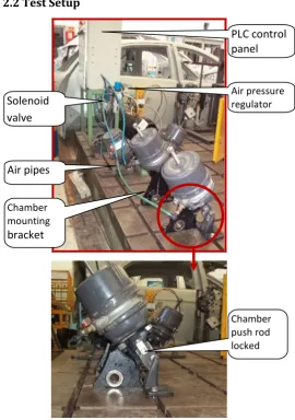
[image:2.595.306.577.347.732.2]2.2 Test Setup
Figure 3 – Endurance test setup photograph. PLC control panel
Solenoid valve
Air pressure regulator
Air pipes
Chamber mounting bracket
© 2016, IRJET | Impact Factor value: 4.45 | ISO 9001:2008 Certified Journal | Page 3003 2.3 Test procedure
Test setup is made without using axle & brake assembly. A chamber mounting bracket is mounted on rigid surface plate. Air chamber is mounted on bracket. Here stroke of chamber push rod is locked by making proper fixture. When high pressure air is supplied to chamber, immediately reaction force acts on bracket because there is no movement of push rod. In conventional method of testing reaction force comes into picture after competing stroke of push road. In this case push rod stroke, ‘S’ cam shaft rotation, brake lining movement is completely eliminated, So maximum cycle rate can be achieved up to 30 cycles / minute.
3. VIBRATION TEST
Consumers expect and demand products of high quality and reliability. To fulfill these requirements we must consider vibration, since at some time in its life the product will be subjected to vibration. Poor mechanical design will result in mechanical failure and customer dissatisfaction which will add cost and reduce credibility.
3.1 Reasons of vibration test
Reduce product development time. Avoid field failures.
To develop full proof system.
Ensure new products are fit for purpose.
3.2 Test setup
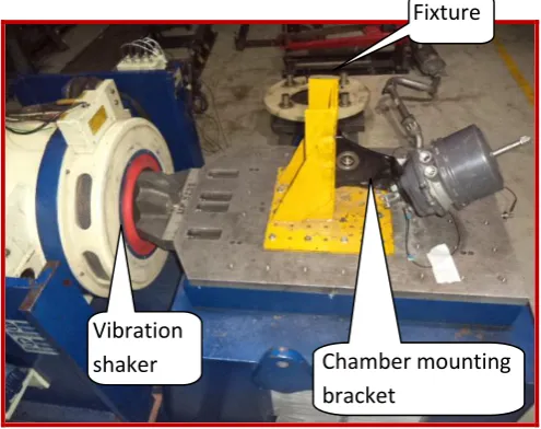
A test fixture has made to mount chamber mounting bracket on vibration shaker. A Saraswati Dynamics make 1.5 Ton, multi axial (i.e. X, Y & Z) vibration shaker is used for testing. In vibration testing it is important to maintain actual field condition of test item. Hence, fixture has designed in such a way that, it simulates actual field condition for chamber mounting bracket. Air chamber has been mounted on bracket to simulated dead load on bracket. A test fixture has bolted to vibration base table. Two ICP type accelerometers have been used for measuring acceleration level of vibration base table & chamber mounting bracket. A PC & controller are used to program the vibration shaker as
[image:3.595.308.556.223.419.2]per requirement. A computer is used to feed all input parameters required for testing. The function of controller is to check whether the vibration shaker is running as per program & controller gives command to power amplifier to increase / decrease electrical supply to shaker in order to maintain the programmed parameters. Figure 4 shows the vibration test setup in X, direction.
Figure 4 – Vibration test setup
4. Deflection Measurement Test
4.1 Reasons of Deflection Measurements
Deflection causes energy loss
Excessive deflection leads to structural failure Excessive deflection causes misalignment /
dislocation of mating part. Deflection reduces response time Increases failure rate
Due to the above mentioned reasons, deflection measurement is one of the important tests of chamber mounting bracket. As shown in test setup, a dial gauges are placed near the mounting of chamber bolts, where there will be maximum chances of deflection.
4.2 Deflection Measurement Test Setup
Two dial gauges of 0 to 10 mm range are placed at extreme end of bracket. Brake chamber air pressure is gradually increased, from 1 bar to 8.1 bar. A deflection
Chamber mounting bracket
Fixture
© 2016, IRJET | Impact Factor value: 4.45 | ISO 9001:2008 Certified Journal | Page 3004 observed on dial gauges are recorded at every one bar
[image:4.595.308.571.112.517.2]increment of air pressure. Figure 12.5 shows test setup details.
Figure 5 – Deflection measurement test setup
5. Natural Frequency Detection Test:
Natural frequency was detected on electro dynamic vibration shaker. Forced natural frequency detection method is used to find the natural frequency of chamber mounting bracket. In forced natural frequency detection method, objected is being forced to vibrate with gradually increasing excitation frequency. When excitation frequency approaches to the natural frequency of component, large amplitude occurs. 5.1 Reasons of Natural Frequency Detection Test
At natural frequency / resonance frequency, component vibrated excessively thereby increasing chances of failure.
Higher amplitude of bracket can lead to develop crack or leads to failure of bracket.
Chances of misalignment with mating part because higher displacements.
Increase in noise level of component.
Because of above reasons natural frequency detection test is important. Resonance is unavoidable. Resonance frequency is detected to check that, whether it should not match with operating frequency or lie within the operating frequency range.
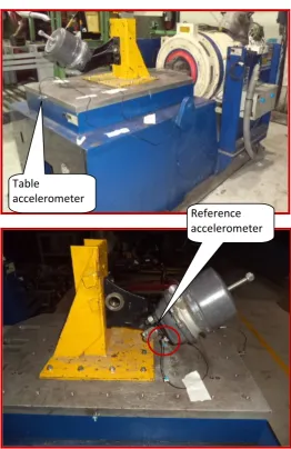
5.2 Test Setup
Figure 6 -Natural frequency detection test setup
A Saraswati Dynamics make 1.3T vibration shaker is used to detect the natural frequency of chamber mounting bracket. Below figure shows photograph of test setup. One accelerometer is mounted on vibration bed / table & another accelerometer is mounted on chamber mounting bracket as shown. As far as possible, farthest point of chamber mounting bracket is selected to mounted accelerometer, so that; maximum bracket acceleration can be measured. Using computer software, a program is made to search natural frequency. An acceleration of 1g is given to vibration table. Then, excitation frequency of vibration shaker is gradually increased from 10 Hz to 300 Hz. As programmed, a vibration shaker starts at 10 Hz, & Dial
gauges Air pressure gauge
Reference accelerometer Table
[image:4.595.38.288.153.342.2]© 2016, IRJET | Impact Factor value: 4.45 | ISO 9001:2008 Certified Journal | Page 3005 gradually increases frequency of vibration table. As test
fixture is rigidly mounted on vibration table & test bracket is mounted on fixture. As excitation frequency of vibration table increase, at the same time, bracket vibration frequency also increases. As bracket approaches to the resonance frequency, acceleration level on bracket increases & after certain increase in acceleration, suddenly it decreases, that is the indication of resonance. Associated frequency which is responsible to for maximum acceleration is called as natural frequency.
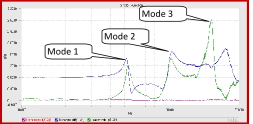
[image:5.595.37.290.306.430.2]5.3Natural frequncy detection test result
Figure 7 – Natural Frequency detection test result
6. CONCLUSION
Endurance test completed 1 million cycles without any structural failure.
Maximum deflection observed is less than 2 mm. Vibration test completed total 8 hrs. At 16g
acceleration & 67 Hz frequency in vertical, horizontal & lateral direction.
Natural frequency (mode) found at 52 Hz, 105 Hz & 195 Hz
ACKNOWLEDGMENT
I gratefully acknowledge Mechanical engineering department of ACEM, Pune for technical support and providing the research facilities. I would also like to thank to Dr. S.B. Padwal, Principal (ACEM, Pune) and Prof. V.R. Bajaj, HOD (Mechanical department) for their help and dedication toward my research and related research, also my friends for their directly & indirectly help, support and excellent cooperation.
REFERENCES
[1] Lev Klyatis “About Trends in the Strategy of Development Accelerated Reliability and Durability Testing Technology”, SAE International, 2012-01-0206.
[2] Hari Shrinivas Babu A, Swapnil R. Salunkhe, “Accelerated Life Test To Predict Fatigue Life Of Small Manual Steering Gearbox” SAE International, 2007-01-0635.
[3] Vyankatesh Madane, Abhijit Swami, Mihir Shah, S.S. Sane, “Creation & Elevation of Mini-Truck Accelerated Endurance test Cycle” SAE International, 2013-26-0154.
[4] Chandrakant Awate, Suyog Panse, Colin Dodds, “Validation of an Accelerated Test on a 4-Post Road Simulator” SAE International, 2007-26-070.
[5] Gagandeep Singh Risam, Shivakumar Balakrishnan, M. G. Patil, Ravi Kharul, “Methodology for Accelerated Vibration Durability Test on Electro dynamic Shaker” SAE International, 2006-32-0081 / 20066581.
[6] Sunil KV, Sunil Sheepri, Kiran Kandula, Amit Kumar, “Integrated Approach for Accelerated Fatigue Testing of Resonating Structure” SAE International, 2014-01-0821. [7] Uday Senapati, Yogesh Dhage, Vinaya Sawant, M.R. Saraf, Colin Dodds, “Accelerated Test Methods for Validation of Vehicle Components Subjected to Fatigue Failure” SAE International, 2007-26-072.
[8] Luis A, Escobar and William Q. Meekaer, “A review of accelerated test models” Statistical Science, 2006 Vol. 21, No 4, 552-577.
BIOGRAPHIES:
Mr. Sagar Awate is studying in
M.E - Mechanical design
engineering at Alard college of Engineering and Management. Marunji, Pune, India
E-mail- [email protected]
Mr. Vidyasagar R. Bajaj is working
as HOD, Department of
Mechanical Engineering at Alard College of Engineering & Management, Marunji, Pune. India.
Mr. Arun Bhosale is working as Assistant Professor, Department of Mechanical Engineering at Sinhgad Academy of Engineering Kondhwa, Pune.
Mode 1
Mode 3
Mode 2