© 2017, IRJET | Impact Factor value: 6.171 | ISO 9001:2008 Certified Journal | Page 1397
MIMO COMMUNICATIONS
Sana Zeba Bakshi
1, Sadiya Mirza
21,2
Student, M.Tech 1
styear, Dept. Of Electronics and Communication Engineering, Anjuman College Of
Engineering & Technology, Nagpur, Maharashtra, India
---***---Abstract –
Multiple-input multiple-output (MIMO)communication technology has proved itself as a widely used technology nowadays. MIMO can be generally referred to as a communication channel which has multiple numbers of transmitters and receivers of antenna which directly affects the communication’s performance. These days MIMO communication technologies are used in various technologies such as long-term evolution (LTE) and Wi-Fi. In this article, we discuss the different terminologies related to the MIMO communication systems such as its narrowband model characteristics, MIMO channel capacity and decomposition of the channel, various types of its diversity gain based methodologies & also its space-time modulation and coding techniques. This paper provides a brief summary of various multiple-input multiple-output technologies emphasizing its various characteristics.
Key Words: Narrowband MIMO model, parallel
decomposition of the MIMO channel, MIMO channel capacity, MIMO diversity gain, space time modulation & coding.
1. INTRODUCTION
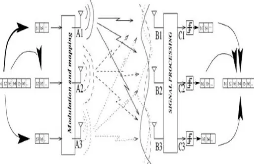
[image:1.595.343.543.287.417.2]Multiple-input multiple-output or MIMO is a radio communications technology which is basically a communication channel with multiple transmitters and receivers of an antenna so as to improve the overall performance of the system. MIMO attains space measurements to enhance the capacity of a wireless system, its range and also reliability. It provides higher data throughput and link range without the requirement of any additional bandwidth or transmitting power. MIMO has been around for many years but using it in wireless system is a newer phenomenon.
Fig-1: Schematic of a wireless MIMO system
1.1
Narrowband MIMO model
Consider a narrowband MIMO channel n this section.A narrowband also known as a flat fading point to point communication system which employs n transmit and m receive antennas as shown in figure 1.1.
Fig 1.1 : MIMO systems
This system can be represented by the discrete time model as follows:
Or a simple representation could be ȳ = Hx + Ñ x = n-dimensional transmitted symbol
Ñ = m-dimensional AWGN vector H = channel matrix
The H-matrix consists of zero Rayleigh fading complex circular random variables hij representing the channel gain from transmit gain j and antenna gain i. We normalize the noise without the loss of generality so that the covariance matrix of noise is an identity matrix. Note that x y nd used here are all stochastic processes. Consider that the receiver is able to estimate every value of H perfectly so that each value of H is known at the receiver.
The transmit power is constrained by:
[image:1.595.321.548.479.525.2]© 2017, IRJET | Impact Factor value: 6.171 | ISO 9001:2008 Certified Journal | Page 1398 Or equivalently given by:
1.2
Parallel decomposition of MIMO channel
Assume the case of a perfect channel state at the transmitter (CSIT) i.e. each value of H is known by the transmitter and the receiver. Consider a single value decomposition (SVD) for an instantaneous channel matrix as:
H = U ʌ V - [1]
U & V = unitary matrices
(i.e.
UU† = In and VV† = Im) ʌ = diagonal matrix of singular values of H.Consider that the transmitter selects
M
=
V†
and the receiver selectsF
=
U†
. The MIMO ch nnel is converted into r(≤min
(m,n)) parallel non-interfering single-input single-output (SISO) channels:
Where,
The parallel decomposition of MIMO channel is shown below:
Fig-1.2: Parallel decomposition of MIMO channel
The demodulation complexity is now r│X│ inste d of │X│r.Note that the multiplication by a unitary matrix does not distributes the AWGN.
1.3. MIMO channel capacity
The MIMO decomposition mentioned above permits a simple description of the MIMO channel capacity when the transmitter and receiver both has the complete knowledge of H. The capacity formula is given by:
Where the maximum is considered the overall matrices Q, which satisfies the constrained average power.
Substitution of SVD matrix and the properties of unitary matrices in the above equation gives:
which is equivalent to flat fading or in frequency selective fading having constant channel gains.
Thus a similar water-filling power allocation for the MIMO channel is thus obtained having the eigen values:
For some cutoff values –λ0 nd λ1=λi2 P/ (N0B).
Thus the channel capacity is given by:
1.3
MIMO Diversity gain
MIMO diversity gain is classified into the following categories:
1) Beam forming
2) Diversity-multiplexing trade-offs
1.3.1
Beam forming
A transmit approach in which the co-variance matrix has a unit rank then it is called as beam forming. Figure illustrates the configuration of a MIMO channel with beam forming.
Fig-1.3.1: MIMO channel with beam forming
1.3.2
Diversity-multiplexing trade-offs
© 2017, IRJET | Impact Factor value: 6.171 | ISO 9001:2008 Certified Journal | Page 1399 R*max = maximum multiplexing gain reachable in a channel
D*max = d*(0) is the maximum gain attainable
For a m×n MIMO channel, it can be easily shown that:
[image:3.595.318.559.55.295.2] [image:3.595.52.273.249.738.2]Figures illustrated below shows a 1×1 channel ,2×1 channel and 2×2 channel characteristics based on spatial multiplexing gain and diversity gain respectively.
[image:3.595.51.273.252.465.2]Figure 1.3.2.1: Example of 1× 1 channel
Fig-1.3.2.2: Example of 2× 1 channel
Figure 1.3.2.3: Example of 2 × 2 channel
1.4
Space time modulation and coding
In this article , our major concentration will be on Space time block code (STBC),space time trellis coding(STTC), spatial multiplexing and Blast architectures.
1.4.1 Space -time block code (STBC)
MIMO systems makes use of space-time block codes to allow the transmission of many number of copies of an information stream over a number of antennas and to utilize the multiple received data units to enhance the capability of data transfer. Space time coding helps to combat major problems like fading and thermal noise because of the use of number of copies of data .
In the space time block coding scheme, the stream of data is encoded in the form of blocks before the transmission takes place. These blocks of data are segregated over multiple antennas and spacing in time domain is also done.
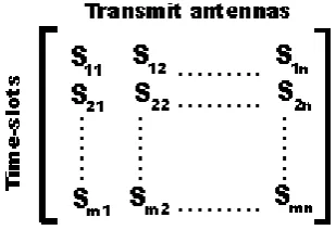
The general representation method used for representing space time block code is by a matrix as shown below:
[image:3.595.360.515.628.734.2]© 2017, IRJET | Impact Factor value: 6.171 | ISO 9001:2008 Certified Journal | Page 1400 Time slot is represented by e ch row nd one ntenn ’s
transmission in time domain is represented by each column.
1.4.2 Space-time trellis code (STTC)
Space-time trellis codes makes use of a scheme in which the transmission of redundant copies of data in done in both time and space by making use of multiple numbers of antennas. These copies of the redundant data sets are utilized by the receiver to recover the original transmitted data.
Space-time trellis codes are able to give coding and diversity gain along with improved bit error rate performance. Complexity of encoding and decoding increases as it makes the use of trellis codes.
1.4.3 Spatial multiplexing
Spatial multiplexing is a technique widely used in MIMO communications to send independent data streams which are separately encoded by using the multiple transmit antennas. The multiplexing of space dimensions is done or reutilization is done multiple times hence it is called as spatial multiplexing.
If the transmitter consists of Nt transmit antennas and Nr receive antennas then the maximum spatial multiplexing is given by:
Ns =min (Nt ,Nr) (in case of a linear receiver)
[image:4.595.309.567.184.350.2]The overall spectral efficiency can be thus increased as the multiple numbers of streams are transmitted in parallel approach. Practically the multiplexing gain can be reduced by the use of spatial correlation technique which channelizes that few of the parallel data streams can have low gain.
Fig 1.4.3: Spatial Multiplexing
1.4.4 BLAST Architectures
Bell Labs Layered Space Time (BLAST) architectures are a family of architectures which came into view for systems which employs multiple antenna arrays at both the transmitter and receiver end.
Fig 1.4.4: BLAST architecture
In this article, we only consider the overview of the various BLAST architectures. The BLAST architectures are categorized into three types:
1) D-BLAST architecture 2) V-BLAST architecture 3) Turbo BLAST architecture
1.4.4.1 D-BLAST Architecture
It is the original scheme of BLAST architecture family with diagonally layered architecture i.e. it uses diagonally layered coding sequence. The layered design of D-BLAST architecture has number of layers equal to the number of antennas in which each layer is coded independently.
The major advantage of the D-BLAST architecture is that it fully utilizes the spatial and time diversity. Due to full utilization of spatial and time diversity it requires multiple numbers of decoders which introduces the drawback of complexity.
[image:4.595.52.563.515.752.2]© 2017, IRJET | Impact Factor value: 6.171 | ISO 9001:2008 Certified Journal | Page 1401
1.4.4.2 V-BLAST Architecture
[image:5.595.311.553.109.411.2]The Vertical BLAST architecture is a much simpler architecture as compared to the D-BLAST architecture with reduced computational complexity which in turn lowers its transmit diversity.
Fig 1.4.4.2: V-BLAST architecture
1.4.4.3 Turbo BLAST Architecture
Another BLAST architecture proposed by Sellathurai and Haykin based on the turbo principle which was later generalized by the Threaded Space-time architecture (STS) by Hammons and ElGamal.
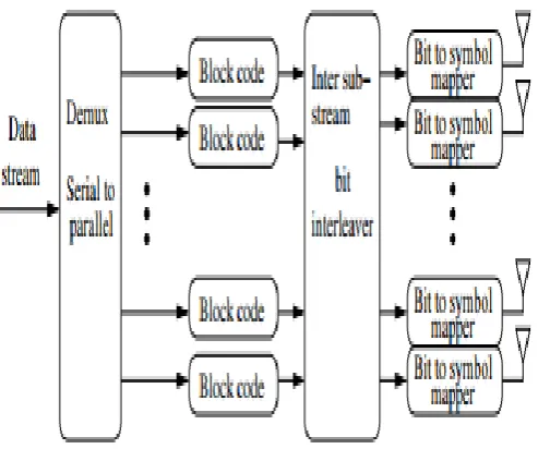
[image:5.595.42.283.181.278.2]The Turbo BLAST architecture uses random layered space-time coding scheme (RLST) before transmission at the encoder. The encoder & decoder of turbo BLAST architecture is shown in the below mentioned figures respectively.
Fig 1.4.4.3.1: Encoder of Turbo BLAST architecture
Fig 1.4.4.3.2: Decoder of Turbo BLAST architecture
2. CONCLUSIONS
MIMO communications is a much widely used concept in the field of wireless communications nowadays. Various technologies such as LTE & Wi-Fi are the fastest growing technologies in MIMO wireless communications. Parallel decomposition of MIMO channel ,its diversity gain and various BLAST architectures for MIMO communications. The concept of spatial multiplexing can also be used to increase the spectral efficiency of the MIMO wireless communication systems. The major concepts of MIMO communication in wireless networks are aforementioned.
REFERENCES
[1]
www.cs.ucdavis.edu/~liu/289I/Material/book-goldsmith.pdf
[2]
https://www.slideshare.net/onecolorheart/mimo-27833829
[3]
http://www.radio- electronics.com/info/antennas/mimo/precoding-codes-alamouti-diversity-space-time.php
[4] https://en.wikipedia.org/wiki/Space%E2%80%93time
[image:5.595.36.283.463.669.2]