© 2017, IRJET | Impact Factor value: 5.181 | ISO 9001:2008 Certified Journal | Page 1684
Graphical Method to Determine Minimum Cutting Fluid Velocity for
Effective Hole Cleaning
Sanjay Joshi
1, Arman Bhaisare
21
Asst. Professor, Dept, of Petroleum Engineering, MIT College Pune, Maharashtra, India
Student of M.E Petroleum Engineering, MIT College Pune, Maharashtra, India
---***---Abstract
- Drilling cutting removal is a vital factor for a good drilling program. In directional and horizontal drilling, It is a common and costly problem. Ineffective removal of cuttings can result in several problems such as slow drilling rate, high torque and drag and in the worst case the drill pipe can be stuck. If this type of situation is not handled properly, the problem can lead to side tracking or loss of well, at worst condition. Cuttings transport is controlled by many variables. A large number of papers have been published to explore and solve this problem over the last 30 years.The studies were directed towards investigating various parameters that affect the cuttings transportation in both vertical and horizontal wellbore. The main objectives of this work are to make a sufficient review of the previous studies, explain the basic of the cuttings transport parameters and models. To draw conclusions about what we can learn from earlier studies .On this paper a simplified graphical chart has been developed .Access the technology at the rig site has been greatly improved by development of this simplified charts for easy understanding. Simplified chart which is used to finding out the critical transport fluid velocity needed for hole cleaning as a function of mud weight, cutting size, plastic viscosity, yield point, hole size and rate of penetration. The proposed chart is easy to use and quick results, making it suitable for field application, results. The models are also be used for giving conclusion of privies studies.Key Words: (Drilling cutting, hole cleaning, Graphical
method, Cutting Velocity, )
1.
INTRODUCTION
Transportation of cuttings is a mechanism that is a vital factor for a good drilling program. In directional and horizontal drilling, hole cleaning is a common and costly problem. Ineffective removal of cuttings can result in several problems, such as bit wear, slow drilling rate, increased ECD. Cuttings transport is controlled by many variables such as well inclination angle, hole and drill-pipe diameter, rotation speed of drill pipe (RPM), drill-pipe eccentricity, rate of penetration (ROP), cuttings characteristics like cuttings size and porosity of bed and drilling fluids characteristics like flow rate, fluid velocity, flow regime, mud type and non -
Newtonian mud rheology. The majority of investigations on the vertical wellbore hole cleaning were performed mainly during the 1970‟s. As new technologies in directional drilling were developed, the research was focused primarily on cuttings transport in inclined and horizontal wellbores. Therefore, this thesis is mainly aimed on inclined and horizontal wellbore cuttings transport. Since this topic has become highly exposed for development and new studies for the last decades, it is possible that the literature review is not fully covered in this research.
In 1981, Iyoho and Azar presented a new model for creating analytical solutions to the problems of non-Newtonian fluid flow through eccentric annuli. During the study first, it was observed that flow velocity was reduced in the eccentric annulus.
In 1983, Hussaini and Azar conducted an experimental study on behavior of cuttings in a vertical annulus. They focused on studying the effect of various factors such as annular velocity, apparent viscosity, yield point to plastic viscosity ratio, and particle size effect on the carrying capacity of drilling fluids.. They concluded that annular fluid velocity had a major effect on the carrying capacity of the drilling fluids.
In 1989, Gavignet and Sobey presented a cuttings transport mechanistic model. In this study they established the critical flow rate above which a bed would not form. According to their calculations, this critical flow rate would occur when the flow was in a turbulent phase.
In 1989, Brown performed analysis on hole cleaning in deviated wells. The study indicated that the most effective drilling fluid for hole cleaning was water in turbulent flow. In 1991, Becker presented a method for mud rheology correlations. They proved that mud rheological parameters improved cuttings transport performance with the low– shear rate viscosity.
Luo (1992) performed a study on flow-rate predictions for cleaning deviated wells. They developed a model was simplified into a series of charts to facilitate rig-site applications.
© 2017, IRJET | Impact Factor value: 5.181 | ISO 9001:2008 Certified Journal | Page 1685 flow rate provided possible control during drilling
operations and were effective solutions of drilling issues In 1993, Larsen developed a new cuttings transport model for high inclination angle wellbores. The model was based on an extensive experimental test on annular hole cleaning in a wellbore with angle interval from 55° to 90° degrees from vertical. The experiment was focused on the annular fluid velocity required to prevent cuttings from accumulating in the wellbore. The aim of the developed model was to predict the minimum fluid velocity that was necessary to keep all cuttings moving.
In 1996, Kenny proposed a new model that combined some developments in the particle settling and rheology area. The model provided a useful tool for the planning of the hole cleaning for highly deviated wells.
Martins 1996 presented results of an extensive experimental program that was focused on the understanding the phenomena evolved in the erosion of a cuttings bed deposited on the lower side of a horizontal annular section. In 1996, Nguyen and Rahman28 introduced a three-layer cuttings transport model that was based on improved understanding of the mechanism and theory of particles transport.The model showed a good agreement with the experimental observations.
In 1996, Hemphill and Larsen 30 performed an experimental research where efficiency of water and oil-based drilling fluids in cleaning the inclined wellbore at varying fluid velocities were studied.
In 1999, Kamp and Rivero presented a two-layer numerical simulation model for calculation of cuttings bed heights, pressure drop and cuttings transport velocities at different rate of penetration and mudflow rates.
In 1999, Rubiandini developed an empirical model for estimating mud minimum velocity for cuttings transport in vertical and horizontal well.
In 2007, Mirhaj et al.37presented results of an extensive experimental study on model development for cuttings transport in highly deviated wellbores. The experimental part of this study focused on the minimum transport velocity required to carry all the cuttings out.
1.1
Summary of literature review:
A lot of studies and experiments were initiated on cuttings transport in 1980‟. By this time, the majority of the scientists were focused on the cuttings transport in the inclined wells. However, some established experimental studies were directed on the cuttings transport in the vertical wellbore. However, most of the research on the vertical drilling was done in the 1970‟s.The cutting transport studies mostly divided on two approaches. First one is an empirical model approach on which most of the scientist studied drilling parameters such as cutting size, mud rheology, flow velocity, viscosity, mud weight etc. to find out there influence on
Cuttings removal rate. The second approach is a theoretical or mechanistic approach. Here, a scientist develops a set of equations by analyzing the forces that are involved in the cuttings transport. These equations are then solved numerically, with certain physical or mathematical assumptions.Despite the large number of the models that had been produced using these two approaches, some of the models needed further development. However, a few models have been presented by combining the theory and best-known practice like Larsen’s model.
1.2
Larsen’s Model
Larsen defined equivalent slip velocity as a flow velocity difference between cuttings and drilling fluid.Equation for slip velocity is given as
𝑽𝒔𝒍𝒊𝒑 = 𝑽𝒔𝒍𝒊𝒑∗𝑪𝒂𝒏𝒈∗𝑪𝒔𝒊𝒛𝒆∗𝑪𝒎𝒘
The equation for critical transport fluid velocity (CTFV or Vcrit) is the sum of cuttings transport velocity (CTV or Vcut) and slip velocity (Vslip):
𝑽𝒄𝒓𝒊𝒕 = 𝑽𝒄𝒖𝒕 +𝑽𝒔𝒍𝒊𝒑
Cuttings transport velocity (CTV or Vcut) can be expressed through a simple mass balance equation as:
Mass generated by drill bit = Mass transported by Mud
𝝆𝒄𝒖𝒕∗𝑸𝒊𝒏𝒋 = 𝑽𝒄𝒖𝒕∗𝑨𝒐𝒑𝒆𝒏∗𝑪𝒄𝒐𝒏𝒄−𝒇𝒕∗𝝆𝒄𝒖𝒕
Cuttings transport velocity in equation is calculated by:
Vcut =
In order to convert volumetric injection rate (Qinj) to ROP, the following equation has been used as
ROP (ft/hr) = Qinj (ft/sec) × ×
To calculate cuttings transport velocity considering ROP, drill-pipe, hole diameter, and fractional cuttings concentration
Vcut =
Uncorrected equivalent slip velocity 𝑽 𝒔𝒍𝒊𝒑 in equation based on experimental data, can be calculated as follows:
𝑽𝒔𝒍𝒊𝒑=𝟎.𝟎𝟎𝟓𝟏𝟔∗𝝁𝒂+𝟑.𝟎𝟎𝟔 𝑭𝒐r 𝝁𝒂<53 𝒄𝒑
𝑽𝒔𝒍𝒊𝒑=𝟎,𝟎𝟐𝟓𝟓𝟒∗(𝝁𝒂−𝟓𝟑)+𝟑,𝟐𝟖 𝑭𝒐𝒓𝝁𝒂>53 𝑐𝑝
© 2017, IRJET | Impact Factor value: 5.181 | ISO 9001:2008 Certified Journal | Page 1686
µ
a= PV +
From experimental investigation, Larsen’s et al. developed an equation for annular cuttings concentration, at critical transport fluid velocity, for inclination angles from 55° to 90° degrees:
𝑪𝒄𝒐𝒏𝒄 = 𝟎.𝟎𝟏𝟕𝟕𝟖∗𝑹𝑶𝑷 + 𝟎.𝟓𝟎
Correction factor given by Larsen’s:
The cuttings size correction factor is expressed by:
𝑪𝒔𝒊𝒛𝒆 = −𝟏.𝟎𝟒∗𝑫𝑪𝒖𝒕𝒕𝒊𝒏𝒈𝒔 +𝟏.𝟐𝟖𝟔
Based on experiments, a correction factor for mud weight was developed:
𝑪𝒎𝒘 = 𝟏−𝟎.𝟎𝟑𝟑𝟑(𝝆𝒎 –𝟖.𝟕) 𝝆𝒎 > 8.7
Cmw = 1 for 𝝆𝒎 < 8.7
Correction factor for inclination is calculated by the following expression:
𝑪𝒂𝒏𝒈 = 𝟎.𝟎𝟑𝟒𝟐𝜽𝒂𝒏𝒈 –𝟎.𝟎𝟎𝟎𝟐𝟑𝟑𝜽𝒂𝒏𝒈2 –𝟎.𝟐𝟏𝟑
1.3 Hopkins Model:
The effect of mud weight on the slip velocity is obtained by the following equation:
Fmw = 2.117-0.1648 * ρm + 0.003681* ρm2
Slip velocity in ft/min (Vsv) is obtained from figure by inputting the value of yield point and assuming average cutting size. The adjusted vertical slip velocity considering the effect of mud weight and yield point is calculated by using the following equation.
Vs = Fmw * Vsv
The minimum mud velocity for in the non vertical section is calculated as follows:
Vmin = (Vs* cos ϴ) + (V2* Sin ϴ)
Where,
V2 = C × 0.166
Where C is the empirical constant based on a laboratory data varies from 40 to 60. Therefore the minimum flow in GPM can be calculated as:
Qcritical = 0.04079 (dh2-dp2)* Vmin
So by knowing both the methods it will take so much time to calculate minimum flow velocity required to remove out drilling cuttings. The calculation based on this chart is also complex.
2.
METHODOLOGY
Graphical method:
Step 1: Find out slip velocity (Vslip) from the chart by using yield point value
Step 2: Add correction factor for inclination angle (Cang) from table
© 2017, IRJET | Impact Factor value: 5.181 | ISO 9001:2008 Certified Journal | Page 1687 Step 4: Add cutting velocity (Vcut) values from table
[image:4.595.43.279.269.438.2]Fig . Cutting velocity for 17.5” hole
[image:4.595.44.279.473.636.2]Fig . Cutting velocity for 12.25” hole
Fig . Cutting velocity for 8.5” hole
Step 6: Find out minimum cutting fluid velocity (Vmin)
Vmin (m/min)= Vcut + 1.2 *(Vslip*Cmw*Cang) for inclination < 30
Vmin(m/min) = Vcut + (Vslip * Cmw * Cang) for inclination > 30
3. APPLICATION OF METHOD
3.1 Mud weight is varying parameter:
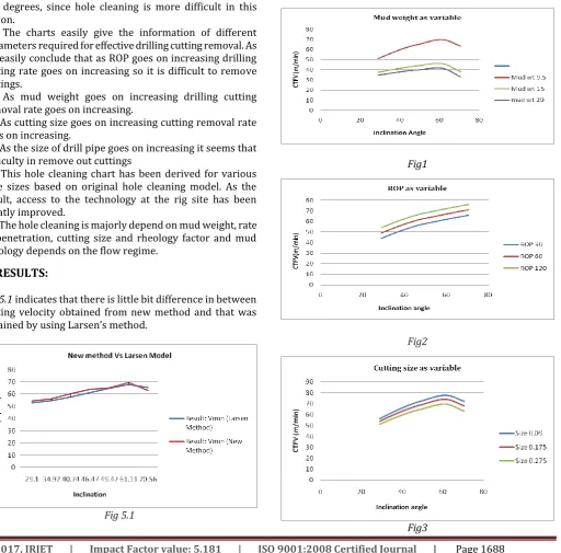
Figure 1 represents flow velocity in annulus versus pipe inclination, with mud weight as a varying parameter.Figure indicates that with increasing mud weight, the flow velocity decreases. Therefore, cuttings transport improves at higher mud weight. Another important observation indicates that the flow velocity lines are curved at the angle between 65° and 80° degrees meaning that higher flow velocity is required to transport cuttings in this angle range. Moreover, the flow velocity with mud weight equal to 20 ppg looks more linear compared to the 9.5 ppg line that is more curved. It seems that flow velocity (CTFV) with high mud weight is only slightly affected by inclination angle.
3.2 ROP as varying parameter:
Figure 2 indicates the ROP as a varying parameter and values are 30 ft/hr, 60 ft/hr, and 120 ft/hr .The rest of data set is constant as listed.As observed from figure 2 higher ROP value requires higher flow velocity for cuttings transport, due to increase in cuttings concentration in annulus. As it was noticed in the previous figure, the flow velocity lines are slightly curved at the angle interval between 65° and 80° degrees.
3.3 Cutting size as a varying parameter:
Figure 3 consider the effect of cuttings size as a varying parameters. Cuttings size of 0.275 inch, 0.175inch, and 0.09 inch was chosen for the simulation. The rest of data set is constant as listed during the simulation.
Figure shows the relationship between the cuttings size and the required cuttings transport flow velocity. From the observations, it is clear that smaller cuttings are more difficult to transport to surface since they require higher flow velocity than larger cuttings. This means that larger cuttings are easier to transport in inclined wellbore than smaller cuttings.
3.4 Drill pipe diameter as a varying parameter:
The values considered for drill-pipe diameter as a varying parameter are 2.375 inch, 3.5 inch and 5.493 inch (Figure 4). The rest of data set is constant as listed during the simulation.
As it is observed from the graph, larger drill pipe diameter (smaller annular areal) requires higher flow velocity for cuttings transport.
4. CONCLUSION:
© 2017, IRJET | Impact Factor value: 5.181 | ISO 9001:2008 Certified Journal | Page 1688 high torque, and drag. Annular cuttings concentration is the
parameter that should be considered for the cuttings transport in directional well drilling. In case of highly inclined or tight well, it is important to ream the wellbore with help of a back reamer. It helps creating a bigger hole that can eliminate risk of stuck drill-pipe.
(2) In the wellbore with inclination angle from 0° to 45° degrees, laminar flow in annulus and increasing yield value of mud to its limit is recommended. In the intermediate inclination from 45° to 55° degrees, it is possible to use either turbulent or laminar flow. In the high deviated wellbore with inclination angle from 55° to 90° degrees, a turbulent flow regime has a better effect on hole cleaning than laminar flow.
(3) Small cuttings create more packed cuttings bed. The height of cuttings bed is higher at inclination between 65° to 70° degrees, since hole cleaning is more difficult in this region.
(4) The charts easily give the information of different parameters required for effective drilling cutting removal. As we easily conclude that as ROP goes on increasing drilling cutting rate goes on increasing so it is difficult to remove cuttings.
(5) As mud weight goes on increasing drilling cutting removal rate goes on increasing.
(6) As cutting size goes on increasing cutting removal rate goes on increasing.
(7) As the size of drill pipe goes on increasing it seems that difficulty in remove out cuttings
(8) This hole cleaning chart has been derived for various hole sizes based on original hole cleaning model. As the result, access to the technology at the rig site has been greatly improved.
(9) The hole cleaning is majorly depend on mud weight, rate of penetration, cutting size and rheology factor and mud rheology depends on the flow regime.
[image:5.595.308.565.65.233.2]5. RESULTS:
[image:5.595.52.565.287.792.2]Fig 5.1 indicates that there is little bit difference in between cutting velocity obtained from new method and that was obtained by using Larsen’s method.
Fig 5.1
Fig 5.2
Fig 5.2 indicates that there is little bit difference in between cutting velocity obtained from new method and that was obtained by using Hopkins Model.
Fig1
Fig2
© 2017, IRJET | Impact Factor value: 5.181 | ISO 9001:2008 Certified Journal | Page 1689 Fig4
NOMENCLUTURE:
Aann = Area of annulus (ft2) Abed = Area of cuttings bed (ft2)
Aopen = Area open to flow above the cuttings bed (ft2), Cang = Correction factor for inclination (dimensionless) Cconc = Fractional cuttings concentration by volume, Cmw = Correction factor for mud density (dimensionless) Csize = Correction factor for cuttings size (dimensionless) Dh = Hole diameter (inch),
Dp = Drill-pipe diameter (inch) PV = Plastic viscosity (cP)
Qinj = Volumetric injection rate of cuttings, (ft3/sec), (m3/sec)
ROP = Rate of penetration (ft/hrs), (m/hrs) Vcrit = Critical velocity (CTFV), (ft/sec), (m/min)
Vcut = Cuttings transport velocity (CTV), (ft/sec), (m/min) Vslip = Slip velocity (m/min)
YP = Yield point (lbf/100 ft2), (Pa)
𝛍 a= Apparent viscosity (cP), (Pa*s)
𝜽𝒂𝒏𝒈= Angleof inclination of wellbore from vertical (degrees)
ρcut = Density of cuttings, (lbm/gal), (kg/m3) ρm = Density of drilling fluid, (lbm/gal), (kg/m3)
REFERENCES
(1) Larsen, T.I., Pilehvari, A.A., and Azar, J.J.: “Development of a New CuttingsTransport Model for High-Angle Wellbores Including Horizontal Wells,” paper SPE 25872 presented at the 1993 SPE Annual Technical Conference and Exhibition, Denver, April 12 – 14.
(2) Rudi Rubiandini, R.S.: “Equation for Estimating Mud Minimum Rate for Cuttings Transport in an Inclined-Until-Horizontal Well”, paper SPE/IADC 57541 presented at the 1999 SPE Annual Technical Conference and Exhibition, Abu Dhabi, November 8 – 10.
(3)Peden, J.M., Ford, J.T., and Oyeneyin, M.B.: “Comprehensive Experimental Investigation of Drilled Cuttings Transport in Inclined Wells Including the Effects of
Rotation and Eccentricity,” paper SPE 20925 presented at Europec 90, The Hsgue, Netherlands, October 22-24
(4) Kamp, A.M. and Rivero, M.:”Layer Modeling for Cuttings Transport in Highly Inclined Wellbores,” paper SPE 53942 presented at the 1999 SPE Annual Technical Conference and Exhibition, Caracas, April 21 – 23.
(5) Moore, Preston L.: “Drilling Practice Manual,” The Petroleum Publishing Co., Tulsa, 1974.
(6) Hussaini, S.M. and Azar, J.J.:“Experimental Study of Drilled Cuttings Transport Using Common Drilling Muds,” SPEJ, (February 1983), pp. 11-20.
(7) Tomren, P.H., Iyoho, A.W., and Azar, J.J.:“Experimental Study of Cuttings Transport in Directional Wells,” SPEDE (February 1986), pp. 43-56.
(8) Becker, T.E., Azar, J.J., and Okrajni, S.S.:“Correlations of Mud Rheological Properties With Cuttings-Transport Performance in Directional Drilling,” SPEDE (March 1991), pp. 16 - 24.
(9) Luo, Y., Bern, P.A. and Chambers, B.D.:“Flow-Rate Prediction for Cleaning Deviated Wells,” paper SPE/ IADC 23884 presented at the 1992 IADC / SPE Drilling Conference, New Orleans, February 18-21, pp. 367-376.