© 2017, IRJET | Impact Factor value: 6.171 | ISO 9001:2008 Certified Journal
| Page 1091
Higher Order Normal Shear Deformation Theory for Static FG
Rectangular Plates
Ashwinkumar Arun Kokane
PG student, Department of Civil Engineering, S.S.D.G.C.T.’s Sanjay Ghodawat Group of Institutions Atigre,
Kolhapur– 416118, Maharashtra, India
---***---Abstract -
In this paper, static response for simply supported rectangular functionally graded plate which is subjected transverse and sinusoidal load in is studied. The generalized shear deformation theory obtained by author in recent year. Material properties of rectangular plate are supposed to be varying in its thickness direction by using power law. The results are compared and validated with literature available. Modeling is based on HONST & finite element tool ABAQUS.Key Words: Functionally graded material, HONST, Uniform
loading , sinusoidal loading etc.
1.INTRODUCTION
In recent years FG materials have gained advantages and attention for the use of materials in various engineering applications. FG materials are considered as very useful material in structural engineering in the field of spacecraft industries and power generation industries. FG materials are new materials; in which properties of materials are vary smoothly along from one face to the other face. By applying the many possibilities inherent in the FGM concept, it is anticipated that materials will be improved and new function for them created.
In simplest FG materials two different material ingredients change gradually from one face to the other face. The most commonly used FG materials are Metal, Ceramic etc. The ceramic in an FGM acts as thermal barrier effects and protects the metal from corrosion and oxidation, and the FGM is toughened and strengthened by the metallic composition. A mixture of ceramic and metal with a continuously varying volume fraction can be easily manufactured. This eliminates interface problems of composite materials and thus the stress distributions are smooth.
Several researchers has done the research work in this field and they introduced various theories.Sankar (1) presented an elasticity solution for a functionally graded beam subjected to transverse loads. Chakraborty et al. (7) developed new beam element to study the thermoelastic behavior of functionally graded beam structures.Zenkur (4) discussed two dimensional solutions for bending analysis of simply supported functionally graded ceramic metal sandwich plates.Zenkur (5) presented the static response for a simply supported functionally graded rectangular plate
subjected to a transverse uniform load. The generalized shear deformation theory obtained by the author in other recent papers is used.This theory is simplified by enforcing traction-free boundary conditions at the plate faces. The equilibrium equations of a functionally graded plate are given based on a generalized shear deformation plate theory. The numerical illustrations concern bending response of functionally graded rectangular plates with two constituent materials. The influences played by transversal shear deformation, plate aspect ratio, side-to-thickness ratio, and volume fraction distributions are studied. The results are verified with the known results in the literature.
Bhangale et al. (6) studied buckling and vibration behavior of a functionally graded material (FGM) sandwich beam having constrained viscoelastic layer (VEL) is studied in thermal environment by using finite element formulation. The FGM sandwich beam is assumed to be clamped on both edges. The material properties of FGM are functionally graded in thickness direction according to volume fraction power law distribution. Temperature dependent material properties of FGM stiff layer and shear modulus of viscoelastic layer are considered to carry out buckling and vibration analysis.
© 2017, IRJET | Impact Factor value: 6.171 | ISO 9001:2008 Certified Journal
| Page 1092
deformation theories. The theory presented is variationally consistent, has strong similarities with classical plate theory in many aspects. In this theory governing equations are derived from principle of virtual work. The closed form solution of simply supported rectangular plate subjected to sinusoidal loading has been obtained by using Navier method and validation of present theory is performed by comparing some of the present results with the classical theory
.
Sobhy (15) described the vibration and buckling behavior of exponentially graded material (EGM) sandwich plate resting on elastic foundations under various boundary conditions. Swaminathan et al. (13) presented a comprehensive review of the various methods employed to study the static, dynamic and stability behavior of Functionally Graded Material (FGM) plates. Both analytical and numerical methods are considered. The review is carried out with an emphasis to present stress, vibration and buckling characteristics of FGM plates predicted using different theories proposed by several researchers without considering the detailed mathematical implication of various methodologies. The main objective of this paper is to serve the interests of researchers and engineers already involved in the analysis and design of FGM structures.
The FGM plate is made of an isotropic material with material properties varying in the thickness direction only. To make the study reasonably, displacements are given for different homogenization schemes and exponents in the power law that describes through-the-thickness variation of the constituents.
1.1 Matehmatical Model
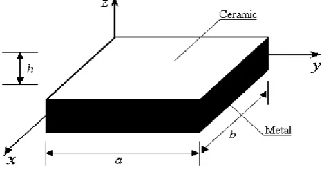
[image:2.595.324.542.354.490.2]Consider a solid rectangular plate of length a, width b and thickness h made up of FG materials as shown in above figure 1.
Figure 1. Geometry of rectangular plate
1.2 Calculation of Material Properties
The materials properties of rectangular plate such as Young’s Modulus is assumed to be the function of volume fraction constituents. The rectangular Cartesian planform
co-ordinates x and y are introduced in the deformation analysis of the present plate. The considered plate is bounded by the co-ordinate planes x = 0 ,a and y = 0 ,b. The reference surface is the middle surface of the plate defined by z = 0, and z denotes the thickness co-ordinate measured from the un-deformed middle surface. The functional relationship between E and z for ceramic and metal FGM plate is assumed as Other font types may be used if needed for special purposes.
E(Z) = Ec + Em x V
Where 2 2
K
z h V
h
Where Ec = Young’s Modulus for ceramic and Em = Young’s
Modulus for metal respectively, K is the volume fraction exponent which has values greater than or equals to zero. The value of K equals to zero represents the plate is fully ceramic. The above power law will helps for the mixture of materials. The variation of material along the thickness of the plate is shown in above figure no2.
Figure 2.Variation in Material in FGM Plate
2. Formulation of HONST
2.1 Equations of equilibriums areThe following differential equations of equilibrium are obtained from the classical theory of elasticity in Cartesian coordinate system (x, y and z)
0
0
0
xy
x xz
x
xy y yz
y
yz
xz z
z
B
x y z
B
x y z
B
x y z
(1)
[image:2.595.41.276.557.683.2]© 2017, IRJET | Impact Factor value: 6.171 | ISO 9001:2008 Certified Journal
| Page 1093
2.1 Strain-displacement relations
From linear theory of elasticity, the general strain-displacement relationships for small strain-displacements can be stated as under.
, , , , , . x y t z xy yz xz
u v w u v v w u w
x y z y x z y z x
(2)
2.2 Constitutive relations
Principal material coordinate system (1-2-3) is used for the stress-strain relationship of fiber-reinforced composites. The axis 1 is aligned with the fiber direction, the axis 2 is perpendicular to the fibers but in the plane of the layer, and axis 3 is perpendicular to the fibers as well as to plane of layer. The stress strain relationship in 1-2-3 coordinate system is as per the following form.
3
1 2
1 21 31
1 2 3
3
1 2
2 12 32
1 2 3
3
1 2
3 13 23
1 2 3
23 13
12
12 23 23
12 23 13
, , , , ,
E E E
E E E
E E E
G G G
(3)
The above relationship for Lth orthotropic elastic layer can be
written in a matrix form as
31 21
1 2 3
32 12
1 1 2 3 1
2 13 23 2
3 1 2 3 3
12 12 12 23 23 13 13 23 13 1
0 0 0
1
0 0 0
1
0 0 0
1
0 0 0 0 0
1
0 0 0 0 0
1
0 0 0 0 0
L L L
E E E
E E E
E E E
G
G
G
(4)
Using Maxwell-Betti reciprocal theorem, there are only 9 independent elastic properties with following relationships.
31 13 32 23
21 12
2 1 3 1 3 2
, , .
E E E E E E (5)
The 3D stress-strain constitutive relationship with stiffness matrix [C] for Lth lamina w. r. t. 1.2.3 can be written
as:
1 11 12 13 1
2 12 22 23 2
3 13 23 33 3
44 12 12 55 23 23 66 13 13
0 0 0
0 0 0
0 0 0
0 0 0 0 0
0 0 0 0 0
0 0 0 0 0
L L L
C C C
C C C
C C C
C C
C
(6)
In which this equation can be written as –
1 23 32 1 21 31 23 1 31 21 32
11 12 13
2 13 31 2 32 12 31 3 12 21
22 23 33
44 12 55 23 66 13
12 21 23 32 31 13 12 23 31
(1 ) ( ) ( )
; ; ;
(1 ) ( ) (1 )
; ; ;
; ; .
and (1 2 ).
E E E
C C C
E E E
C C C
C G C G C G
Substituting,
1 2 3 ; 12 23 13 ; 12 23 13
2(1 ) E
E E E E G G G G ,
following elastic constants are defined for isotropic layer.
11 22 33
12 13 23
44 55 66
(1 )
( 2 );
(1 )(1 2 )
;
(1 )(1 2 )
. 2(1 ) E
C C C G
E
C C C
E
C C C G
(7)
where,
and Gare Lame’s constants.In the laminate coordinate system (x-y-z) the stress strain relationship for Lth lamina can be written as
11 12 13 14
12 22 23 24
13 23 33 34
14 24 34 44
55 56 56 66 0 0 0 0 0 0 0 0
0 0 0 0
0 0 0 0
L L L
x x y y z z xy xy yz yz xz xz
Q Q Q Q
Q Q Q Q
Q Q Q Q
Q Q Q Q
Q Q
Q Q
(8)
where
x, y, z, xy, yz, xz
are the stresses and
x, y, z, xy, yz, xz
are the strains with respect to laminate© 2017, IRJET | Impact Factor value: 6.171 | ISO 9001:2008 Certified Journal
| Page 1094
4 2 2 4 4 4 2 2
11 11 12 44 22 12 12 11 22 44
2 2 3 3
13 13 23 14 11 12 44 12 22 44
4 4 2 2 2 2
22 11 22 12 44 23 13 23 3
24 11 12 44 12 22
2( 2 ) ; ( ) ( 4 ) ;
; ( 2 ) ( 2 ) ;
(2 4 ) ; ;
( 2 ) (
Q C c C C s c C s Q C c s C C C s c
Q C c C s Q C C C sc C C C cs
Q C s C c C C s c Q C s C c
Q C C C s c C C 3
44 33 33 2 2 4 4 34 31 32 44 11 12 22 44 44
2 2 2 2
55 55 66 56 66 55 66 55 66
2 ) ; ;
( ) ; ( 2 2 ) ( );
; ( ) ; .
C c s Q C
Q C C sc Q C C C C c s C c s
Q C c C s Q C C cs Q C s C c
(9)
and Qij Qji, i, j = 1 to 6, where, c = cos(α) and s = sin(α)is the angle made by fiber direction to x-axis.
11 12 13
12 22 23
13 23 33
44
55
66
0 0 0
0 0 0
0 0 0
0 0 0 0 0
0 0 0 0 0
0 0 0 0 0
L L L
x x y y z z xy xy yz yz xz xz
Q Q Q
Q Q Q
Q Q Q
Q Q
Q
(10)
2.3 Displacement Fields
In order to approximate the 3D elasticity problem to a 2D plate problem, the displacement components u(x, y, z), v (x, y, z) and w(x, y, z) at any point in the plate space are expanded in a Taylor series in terms of thickness coordinate z, viz.,
2 3
2 3
2 3
0 0 0
2 3
2 3
2 3
0 0 0
2 2
2 0
1 1
( , , ) ( , , 0) ...
2! 3!
1 1
( , , ) ( , , 0) ...
2! 3!
1
( , , ) ( , , 0)
2!
u u u
u x y z u x y z z z
z z z
v v v
v x y z v x y z z z
z z z
w w
w x y z w x y z z
z z 3 3 3 0 0 1 ... 3! w z z (11)
2.4 Displacement Model
2 * 3 *
0 0
2 * 3 *
0 0 ( , ) ( ) ( ) ( ) ( ) ( , ) ( ) ( ) ( ) ( ) x x z z
u x z u x z x z u x z x
w x z w x z x z w x z x
(12)
2.5 Governing Equations
Using the principle of minimum potential energy, which derives the equation of equilibrium. In analytical form it can be written as,
( ) 0
U V (13)where U is the total strain energy due to deformation, V is the potential of the external loads and U+V= is the total potential energy and
is the variational symbol. Substituting the appropriate energy expressions in the above equation, the final expression can be written as,/ 2
0 / 2
( ) 0
hx x z z xz xz
l l
h
dxdz q w dx (14)
where, 2 * 3 *
0 ( / 2) ( / 4) ( / 8)
z o z
w w h h w h is the
transverse displacement at top surface of the plate. 0
q is the transverse load applied at top of the plate. Integrating the above equation by parts and collecting the coefficients of
0 0
* * * *
0, 0, , , , , ,
u w x z u w x z, the following equations
of equilibrium are obtained.
0: 0, 0: 0 0, : 0, : ( ) 0
2
x x x x
x x z z z
N Q M S h
u w q Q N q
x x x x
0 * * * * * 0 * 2 * * 0 * 3 * * 0
: 3 0,
: 2 0,
: 2 ( ) 0
4
: 3 ( ) 0
8 z z z x x x x x x x M Q x N u S x Q h
w M q
x
S h
N q
x
(15)
Where the stress resultants in terms are defined by
1 1 1 1 1 1 1 1 * 3 1 1 1 * 2 1 1 * 3 1 1 * 1 , , , , , , , ,
L L L L L L L L L L L L L L L Ln Z n Z
x Z x x Z x
l l
Z n
z z
l Z
n Z n Z
x Z xz x Z xz
l l
n Z n Z
x Z xz x h xz
l l
n Z
x Z x x x
l
M zdz M z dz
M zdz
Q dz Q z dz
S zdz S z dz
N dz N 1
1 1 2 1 * 2 1 1 , , .
L L L L L L n Z Z l Z Z n nz z z z
l h l Z
z dz
N dz N z dz
(16)
3. Results and Discussions
In this paper FGM simply supported rectangular plate is studied subjected uniform and sinusoidal loading. Dimensions of the plate are a= 1000, b=1000 and h=100 is considered and calculated by using aspect ratio a/h=10.
Now, a functionally graded material consisting of aluminum and alumina is considered. Young_s modulus for aluminum is 70GPa while for alumina is 380GPa. Note that, Poisson’s ratio is selected constant for both and equal to 0.3. The non-dimensional displacement parameters are calculated by using the following relations –
3 4 0 10 , 2 2 c
h E W a b W
a q
© 2017, IRJET | Impact Factor value: 6.171 | ISO 9001:2008 Certified Journal
| Page 1095
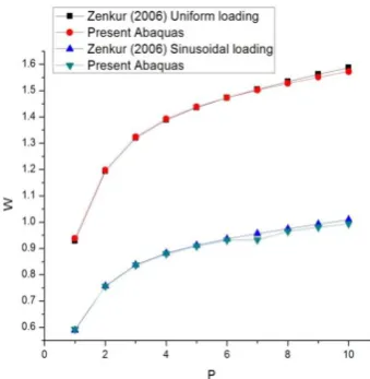
Above table shows comparison between results for plates subjected to uniform or sinusoidal distributed loads, respectively. As it is well known, the uniform load distribution always overpredicts the displacements. As the plate becomes more and more metallic, the difference increases for deflection w. In above table no.1 the non dimensionless displacements of FGM simply supported rectangular plates subjected to uniform loading and non dimensionless displacements of FGM simply supported rectangular plates subjected to uniform loading are given –
Table No. 1 Non-Dimensional transverse displacement for S-S FGM Plate under uniformly distributed loading and
Sinusoidal loading.
K Loading Lit.(5) Present Values
Ceramic UL 0.4665 0.4636
SL 0.2960 0.2926
1 UL 0.9287 0.9382
SL 0.5889 0.5920
2 UL 1.1940 1.1973
SL 0.7573 0.7558
3 UL 1.3200 1.3235
SL 0.8377 0.8356
4 UL 1.389 1.3927
SL 0.8819 0.8793
5 UL 1.4356 1.4383
SL 0.9118 0.9085
6 UL 1.4727 1.4728
SL 0.9356 0.9306
7 UL 1.5049 1.5017
SL 0.9562 0.9317
8 UL 1.5343 1.5276
SL 0.9750 0.9652
9 UL 1.5617 1.5511
SL 0.9925 0.9800
10 UL 1.5876 1.57244
SL 1.0089 0.9937
Metal UL 2.5327 2.54448
[image:5.595.341.511.90.264.2]SL 1.6070 1.6404
Figure 3. Comparison between Lit. (5) & Present Results for Non-Dimensional transverse displacement S/S FGM
[image:5.595.21.560.266.746.2]Plate under uniformly distributed loading & Sinusoidal loading.
Figure 4. Non-Dimensional transverse displacement for S-S FGM Plate under uniformly S-Sinusoidal loading for metal
plate.
Figure 5. Non-Dimensional transverse displacement for S-S FGM Plate under uniformly S-Sinusoidal loading for P=8
[image:5.595.313.555.333.497.2]© 2017, IRJET | Impact Factor value: 6.171 | ISO 9001:2008 Certified Journal
| Page 1096
Conclusion –
The static response of FGM plate is studied using this HONST. This HONST results shows good validation for the results available in the literature. The displacement response of rectangular plate under uniform and sinusoidal loading is studied. Non dimensional displacements for FGM rectangular plate are computed. From the results it is seen that non dimensional vertical displacement of FGM plate goes on increasing for both uniform loading and sinusoidal loading as per the power law distribution. Thus it shows that the gradients in Material properties plays very important role.
REFERENCES
1. Sankar B.V. (2001) “An elasticity solution for functionally graded beams.” Composites Science and Technology, Vol. 61, pp. 689–696.
2. Mantari J.L.(2015) “A simple and accurate generalized shear deformation theory for beams.” Composite Structures, Vol.134, pp. 593–601.
3. Sina S.A, H.M. Navazi (2009) , H. Haddadpour “An analytical method for free vibration analysis of functionally graded beams.” Materials and Design, Vol. 30, pp. 741–747.
4. Zenkour A.M. (2005) “A comprehensive analysis of functionally graded sandwich plates: Part 1—Deflection and stresses.” International Journal of Solids and Structures, Vol.42, pp. 5224–5242.
5. Zenkour Ashraf M (2006)c “Generalized shear
deformation theory for bending analysis of functionally graded plates.” Applied Mathematical Modeling, Vol.30, pp. 67–84.
6. Bhangale Rajesh (2006) “Thermoelastic buckling and vibration behavior of a functionally graded sandwich beam with constrained viscoelastic core.” Journal of Sound and Vibration, Vol. 295, pp. 294–316.
7. Chakraborty A (2003) “New beam finite element for the analysis of functionally graded materials.” International Journal of Mechanical Sciences, Vol. 45, pp. 519–539.
8. Jha D.K, Tarun Kant,R.K. Singh (2013) “A critical review of recent research on functionally graded plates.” Composite Structures. Vol.96, pp. 833–849.
9. Kadoli R et al. (2008) “Static analysis of functionally graded beams using higher order shear deformation theory.” Applied Mathematical Modeling, Vol.32, pp. 2509–2525.
10. Bui T Q (2013) “Dynamic analysis of sandwich beams with functionally graded core using a truly meshfree
radial point interpolation method.” Engineering Structures, Vol.47. pp. 90–104.
11. Hadj Henni ABDELAZIZ , Hassen Ait ATMANE , Ismail MECHAB, Lakhdar BOUMIA, Abdelouahed TOUNSI, Adda Bedia El ABBAS (2011) “Static Analysis of Functionally Graded Sandwich Plates Using an Efficient and Simple Refined Theory.” Chinese Journal of Aeronautics, Vol. 24, pp. 434-448.
12. Huang Song-Jeng (2003) “An analytical method for calculating the stress and strain in adhesive layers in sandwich beams.” Composite Structures, Vol.60, pp. 105–114.
13. Swaminathan K (2015) “Stress, vibration and buckling analyses of FGM plates—A state-of-the-art review.” Composite Structures, Vol.120, pp. 10–31.
14. Gupta Ankit, Mohammad Talha (2015) “Recent development in modeling and analysis of functionally graded materials and structures.” Progressin Aerospace Sciences, Vol.79,pp.1–14.
15. Sobhy Mohammed (2013) “Buckling and free vibration of exponentially graded sandwich plates resting on elastic foundations under various boundary conditions.” Composite Structures, Vol. 99, pp.76–87.