© 2018, IRJET | Impact Factor value: 6.171 | ISO 9001:2008 Certified Journal
| Page 870
Capturing carbon dioxide from air by using Sodium hydroxide
(CO
2Trapper)
Harshdeep Singh
1, Prashant Gupta
2, Akshay Soni
3, Rohit Joshi
4,
Ram Jatan Yadav
5, Ashutosh Singh
61,2,3,4
Jims Engineering Management Technical Campus (JEMTEC-affiliated to GGSIPU)
Department of Mechanical Engineering, Knowledge park 3, Greater Noida, Uttar Pradesh
5,6
Assistant Professor Department of Mechanical Engineering,JIMS Engineering Management Technical
Campus, Greater Noida., India.201308
---***---Abstract -
Carbon dioxide (CO2) emissions have become oneof the most serious issues and this environmental concern is being faced by our civilization today. These emissions are mainly generated from the combustion of coal, oil and natural gas which are the main energy resources in our daily life, economic growth and industrial development. It is widely considered a primary factor in global climate change. In addition, it adversely affects our earth. Switching from fossil fuel would take time and in mean time, emissions will grow to a factor that will take centuries for plants to absorb it. Therefore, we need a solution for this. A possible solution is to capture carbon directly from air same as plants do and store it. This paper presents a way to capture carbon from air by using NaOH. This paper also presents design, materials and cost analysis of prototype created for carbon capturing facility. Reactions and chemicals involved to do so along with experimental data of effectiveness of carbon capturing.
Key Words: Air purifier, Carbon Scrubber, Carbon Capture, Direct Air Capture (DAC), Carbon Dioxide Trapper.
1. INTRODUCTION
It is well known that CO2 plays a dominating role in the
greenhouse gases. Global climate change leads to the high
interest in the technologies relevant to the CO2 capturing
that is one of the potential methods to reduce greenhouse
gas emissions. Carbon dioxide (CO2) emissions have become
one of the most serious issues and environmental concerns facing our civilization today. At present even if we stop using fossil fuels or producing excess co2, we still cannot revert to
the present normal state of the earth so we need to remove the excess co2 more rapidly than flora, as trees would
require a long time to absorb the present excess carbon from the atmosphere. Trees also require large amount of cultivating land of the earth which could be used for productive purpose. Keeping in mind all the challenges faced by humanity this project would help overcome the important problem of global warming.
The amount of carbon dioxide (CO2) in the atmosphere
continues to rise and rather rapidly due to unparalleled
cumulative CO2 emissions, provoking the undesirable
greenhouse gas effect. Certainly, it is becoming critical to develop economical and practical pathways to reduce the CO2 emissions; and appropriately, prospective routes to
address this enduring challenge are considered. (i) CO2
emission reduction from post-combustion stationary and
mobile sources where CO2 concentration is in the range of
10–15% and (ii) CO2 removal from air called direct air
cap0ture (DAC), which is another alternative option to reduce greenhouse gases emissions in a uniform way globally. Although DAC is relatively more challenging than post-combustion capture, it is recognized that it might be practical, provided that suitable adsorbent combining
optimum uptake, kinetics, and energetics and CO2 selectivity
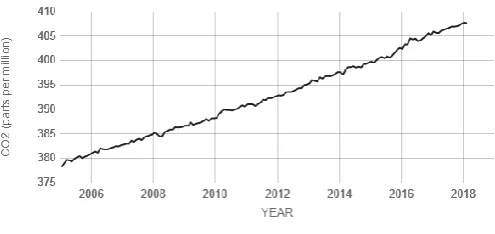
[image:1.595.308.556.426.543.2]is available at trace CO2 concentration.
Figure 1: Carbon dioxide ppm level over the time
1.1 Literature Review
Several methods has been developed and used to capture carbon dioxide from high emission sources and store it in different conditions, some of the featured work that has been done is:
Carbon capture and storage (CCS) involves the separation
and capture of CO2 from flue gas, or syngas in the case of
IGCC. CCS is a three-step process that includes:
1. LiOH absorption solution developed by NASA use same
© 2018, IRJET | Impact Factor value: 6.171 | ISO 9001:2008 Certified Journal
| Page 871
2. Capture of CO2 from electric generating units (or other
industrial processes);
3. Compression and transport of the captured CO2 (usually in
pipelines);
4. Underground injection and geologic sequestration (also referred to as storage) of the CO2 into deep underground rock
formations. These formations are often a mile or more beneath the surface and consist of porous rock that holds the
CO2. Overlying these formations are impermeable,
non-porous layers of rock that trap the CO2 and prevent it from
migrating upward.
Amine scrubbing:
The dominant application for CO2 scrubbing is for removal of
CO2 from the exhaust of coal- and gas-fired power plants.
Virtually the only technology being seriously evaluated involves the use of various amines, e.g. mono-ethanol-amine. Cold solutions of these organic compounds bind CO2, but the binding is reversed at higher temperatures:
CO2 + 2 HOCH2CH2NH2 ↔ HOCH2CH2NH3+ + HOCH2CH2NHCO2−
As of 2009, this technology has only been lightly implemented because of capital costs of installing the facility and the operating costs of utilizing it.
The following subsections provide an overview of CO2
capture technology, CO2 compression, CO2 pipeline
infrastructure for transportation, geologic sequestration, and alternatives to geologic sequestration.
A. CO2 Capture Technology In general, CO2 capture
technologies applicable to fossil-fuel fired power generation can be categorized into three approaches:
• Post-combustion systems are designed to separate CO2 from
the flue gas produced by fossil-fuel combustion in air.
• Pre-combustion systems are designed to separate CO2 and
H2 in the high-pressure syngas produced at IGCC power
plants
• Oxy-combustion uses high-purity oxygen (O2), rather than
air, to combust coal and therefore produces a highly
concentrated CO2 stream.
Source: Literature Survey of Carbon Capture Technology - Environmental Protection Agency (EPA)
Related work:
1. Gary T. Rochelle (2009). "Amine Scrubbing for CO2
Capture".
2. Li, Jian-Rong (2011). "Carbon dioxide capture-related gas adsorption and separation in metal-organic frameworks"
3. F. S. Zeman; K. S. Lackner (2004). "Capturing carbon dioxide directly from the atmosphere"
2. Experiment
Principle of operation
CO2 trapper works on the principle of alkali bases capacity to absorb carbon dioxide and convert it into carbonate. Reaction of the alkali bases with carbon dioxide:
When the alkali solution is a fairly concentrated one (pH>10), carbon dioxide directly reacts with it to form the bicarbonate, which further reacts with the alkali to form sodium carbonate (Na2CO3) as the main product by complete neutralization.
Complete Reaction involved and its intermediate states:
1. Carbon dioxide and water react to make carbonic
acid.
2. Carbonic acid reacts with hydroxide ions to make
bicarbonate ions.
Reaction in aqueous solution:
Now when carbon dioxide in the air had reacted to form sodium carbonate in the aqueous solution to obtain the absorbent solution (NaOH) back into the system, sodium carbonate is reacted with the calcium hydroxide to get NaOH solution back by the following equation:
Setup:
We will be using different percentage of NaOH solution for our testing with the prototype made; 1%, 2%, 3% and 5% (w/w) NaOH solution in distilled water. Ambient air with
average temperature of 30℃ and normal percentage of
© 2018, IRJET | Impact Factor value: 6.171 | ISO 9001:2008 Certified Journal
| Page 872
Dimensions:Hull or Body: 750 x 300 x 750 (L.B.H mm) Filter Structure: 500 x 300 x 550 (L.B.H mm)
Fan : 200mm Diameter (Voltage Regulated)
Nozzle : 0.5mm (5 holes)
Pump : 5-6 Kg hydraulic pressure (110 psi)
Prototype device of above dimensions is taken to run the test for absorption of CO2.
1. Air is made to flow through the system by use of an fan which extract air out of the system continuously and speed of the fan can be regulated to increase or decrease the flow of air, this air first pass first layer of dry filters. These dry filters do not let dirt particles to enter the chamber and make only clean air to be processed.
2. Air then enters the chamber where custom-made NaOH filter is place. NaOH (aq) solution is sprayed from the top of the chamber; nozzles form mist of aqueous solution giving uniform spreading of solution over the filter. Filter is so designed so that, speed of air is reduced enough to give enough time for reaction to occur. The design of filter is such that air must pass aqueous solution layers of NaOH, hence improving reaction and surface area for better efficiency. 3. Passing from NaOH solution filter most of the carbon dioxide is absorbed and remaining air is exhausted out of the chamber via voltage-regulated fan.
4. After absorption of CO2, solution becomes rich in Na2CO3.
This solution is taken to react with Ca(OH)2 to form CaCO3
and NaOH, hence giving back the main working chemical (NaOH). CaCO3 being solid is easy to remove from the aqueous solution.
We used 3, 4, 5% (w/w) solution of NaOH with distilled water to conduct the experiment.
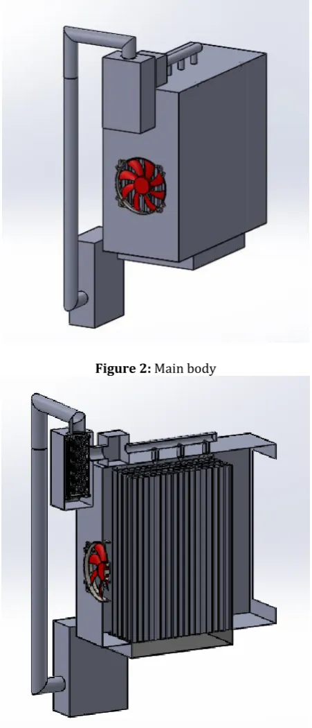
[image:3.595.321.548.105.372.2]2.1 Components and Working
Figure 2: Main body
[image:3.595.321.547.109.635.2]© 2018, IRJET | Impact Factor value: 6.171 | ISO 9001:2008 Certified Journal
| Page 873
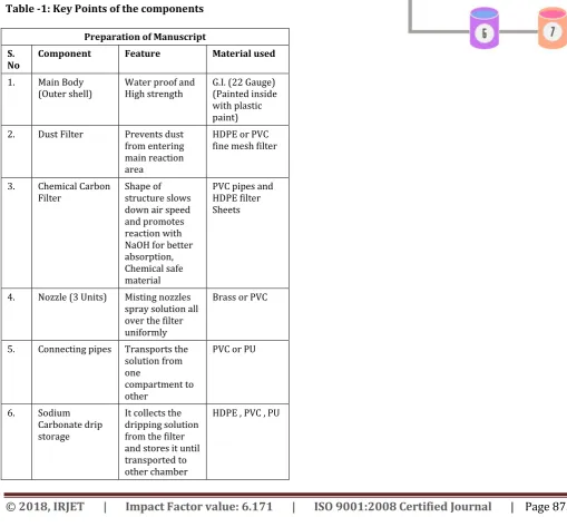
Figure 4: Carbon Dioxide filter (Top View)Table -1: Key Points of the components
Preparation of Manuscript S.
No Component Feature Material used 1. Main Body
(Outer shell) Water proof and High strength G.I. (22 Gauge) (Painted inside with plastic paint)
2. Dust Filter Prevents dust
from entering main reaction area
HDPE or PVC fine mesh filter
3. Chemical Carbon
Filter Shape of structure slows down air speed and promotes reaction with NaOH for better absorption, Chemical safe material
PVC pipes and HDPE filter Sheets
4. Nozzle (3 Units) Misting nozzles spray solution all over the filter uniformly
Brass or PVC
5. Connecting pipes Transports the solution from one
compartment to other
PVC or PU
6. Sodium
Carbonate drip storage
It collects the dripping solution from the filter and stores it until transported to other chamber
HDPE , PVC , PU
7. Fan Voltage regulated
speed control Plastic 8. Chemical storage
compartment It stores both NaOH and Ca(OH)2, leak proof, high strength
HDPE, PVC, Polypropylene or Poly Urethane
9. Pump Circulates
solution with high pressure for nozzles to work
© 2018, IRJET | Impact Factor value: 6.171 | ISO 9001:2008 Certified Journal
| Page 874
Figure 5: Working of prototype systematically1. Ambient air enters through the dust filter (air temp –
30℃ at 1atm); all the dust and macro impurity are filtered here
2. Now air moves to the chemical carbon filter where
NaOH is spraying and structure is such made that air moves slowly while making contact with walls of NaOH solution and crosses HDPE filters many times which increase the chance of Carbon to be reacted with NaOH. In this process Carbon Dioxide from air get filtered out as it reacts with NaOH to form Na2CO3
(Sodium carbonate) and makes air free from Carbon Dioxide.
3. This air free from Carbon exits out of the body via exhaust fan.
4. Sodium carbonate that is made is collected at the
bottom of the carbon filter and taken to chemical storage area where Na2CO3 is made to react with
Calcium Hydroxide (Ca(OH)2) to form NaOH which is
again used in the reaction and Calcium Carbonate which is easy to separate out.
5. NaOH obtained is recirculate repeatedly to filter out
Carbon Dioxide.
3. Results
These experiment results are obtained from 100% carbon dioxide gas fed to the reaction chamber just for testing the
correct working of the project.
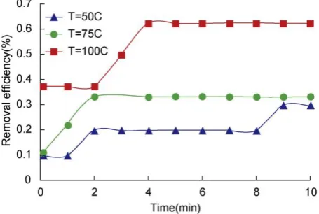
The removal efficiency of CO2 as a function of operating
temperature is shown in Chart 1 with the inlet CO2
concentration of 4%. As observed in the chart 1, with increasing the operating temperature, the reaction rate
increases resulting in enhancement of the CO2 removal
efficiency. Chart 1 shows that the maximum removal efficiency of 63% is related to 100 °C with 3 wt. % of aqueous NaOH for the rate of 0.063 lit/s. Moreover, the sharp change in the green line shown in Chart 1 returns to the accuracy of
the CO2 analyser as well as higher reaction rate.
In order to evaluate the influence of the absorbent concentration, two different aqueous solution of NaOH with the values of 3 and 1 wt. % is used and the results are depicted in Chart 2. As can be seen, increasing the absorbent concentration from 1 to 3 wt. % leads to an enhancement in removal efficiency due to providing higher driving force to the reaction. As the concentration of absorbent is increased, the rate of reaction will also be favoured due to providing higher concentration of the reactant.
These results are obtained from infrared CO2 sensor, air was
heated from a rapid air heater just for testing purposes. Source of this result is Reference [1]: “A novel rate of the reaction between NaOH with CO2 at low temperature in spray dryer” by Yadollah Tavan and Seyyed Hossein Hosseini.
© 2018, IRJET | Impact Factor value: 6.171 | ISO 9001:2008 Certified Journal
| Page 875
Chart 2: Plot for different concentration of NaOHCost Analysis
Cost analysis of components that are used in this system are as follows:
1. Initial cost of body : 12,000 to 16,000 rupees
2. Cost of chemicals :
NaOH : 8200 rupees / Ton (One time)
Ca(OH)2 : 4000 rupees / Ton *(Reoccurring Cost)
3. Cost of Energy: It consumes about 40W – 70W
energy depending upon pump (This energy can be free if solar energy panel is used and results in no carbon emissions)
3. CONCLUSIONS
In practical application of the project ambient temperature of air would be around 30 – 40 ℃ considering weather
conditions in India, ambient air also holds about 0.04% of carbon dioxide hence actual efficiency would certainly be
lowered than ideal 100% carbon rich air.
Conducting experiments along with the structure made by us actual efficiency of carbon removal varied between 30-60%. Carbon removal efficiency grows with increase in temperature and concentration of carbon dioxide in air passing through this filter hence it can be ideal to use in capturing carbon from carbon rich emission sources.
It is ideal for use in:
Power plant emission control Oil refinery and oil extraction emissions control Fossil fuel powered objects like automobiles, etc.
This can also be used for DAC Direct Air Capture, i.e. capturing carbon from ambient air itself.
REFERENCES
[1] “A novel rate of the reaction between NaOH with CO2 at
low temperature in spray dryer” by Yadollah Tavan and Seyyed Hossein Hosseini.
[2] Literature Survey of Carbon Capture Technology -
Environmental Protection Agency (EPA)
[3] “The Carbon Cycle” by Holli Riebeek, Design by Robert
Simmo June 16, 2011 NASA
https://earthobservatory.nasa.gov/Features/CarbonCyc le/
[4] Willis, Richard; Lesch, David A. (2010). "Carbon Dioxide Removal from Flue Gas Using Microporous Metal Organic Frameworks
[5] Gary T. Rochelle (2009). "Amine Scrubbing for CO2 Capture".
[6] Li, Jian-Rong (2011). "Carbon dioxide capture-related
gas adsorption and separation in metal-organic frameworks"
[7] F. S. Zeman; K. S. Lackner (2004). "Capturing carbon dioxide directly from the atmosphere"
[8] M. Wang, A. Lawal, P. Stephenson, J. Sidders, C. Ramshaw
“Post-combustion CO2 capture with chemical absorption: a state-of-the-art review”
[9] M.H. Marzouqi, M.H. El-Naas, S.A.M. Marzouk, M.A.
Al-Zarooni, N. Abdullatif, R. Faiz “Modeling of
CO2 absorption in membrane contractors”
[10] J.M. Amann, M. Kanniche, C. Bouallou “Natural gas
combined cycle power plant modified into an O2/CO2 cycle for CO2 capture”
[11] J. Davison “Performance and costs of power plants with
capture and storage of CO2”
[12] Y. Tavan, S.H. Hosseini “A novel application of reactive
absorption to break the CO2 –ethane azeotrope with low energy requirement”
[13] E. Worrell, L. Price, N. Martin Energy efficiency and carbon dioxide emissions reduction opportunities in the US iron and steel sector
[14] J.-C. Chen, G.-C. Fang, J.-T. Tang, L.-P. Liu “Removal of carbon dioxide by a spray dryer”
[15] S.-M. Shih, C.-S. Ho, Y.-S. Song, J.-P. Lin
© 2018, IRJET | Impact Factor value: 6.171 | ISO 9001:2008 Certified Journal
| Page 876
[16] “Carbon Dioxide Capture from Atmospheric Air Using
Sodium Hydroxide Spray” Joshuah K. Stolaroff§, David W. Keith‡ and Gregory V. Lowry
[17] Microporous metal-organic framework with potential
for carbon dioxide capture at ambient conditions: by Shengchang Xiang, Yabing He, Zhangjing Zhang, Hui Wu, Wei Zhou, Rajamani Krishna & Banglin Chen
[18] Quadrelli, R. & Peterson, S. The energy-climate
challenge: recent trends in CO2 emissions from fuel combustion. Energ.
[19] Rochelle, G. T. Amine scrubbing for CO2 capture.
[20] Haszeldine, R. S. Carbon capture and storage: how green
can black be?
[21] D'Alessandro, D. M., Smit, B. & Long, J. R. Carbon dioxide capture: prospects for new materials. Angew. Chem. Int.
[22] Drage, T. C. et al. Materials challenges for the