F86 Class Schedule
Day 1 Day 2 Day 3
OVERVIEW ADVANCED MCS FNP INTERNALS USAGE
Morning
General Telecomm tty_ Programs and
Concepts TTF Databases
MCS Parts
FNP Description
MCS RING 0 MCS MCS METERING
ADMINISTRATION INTERNALS AND DEBUGGING
After-noon CMF Programs and Ring 0 MCS Meters
FNP Core Image Databases FNP Meters Operator Commands Multics-FNP debug_fnp
MCS Overview
& What is MCS
Multics Communications System
Software to transfer data to/from terminals or other devices connected via communications lines
Sometimes called MCM: Multics Communications Manager
Design is generalized, table-driven
Especially good at supporting diverse asynchronous terminals
In this course most of the major MCS topics are covered
Administration
CMF, TTF, FNP images Use
All Ring 0 interfaces to MCS functions
Internals
I
Ring 0 and FNPMetering and Debugging
Ring 0 and FNP
There are certain topics within MCS or related to MCS that will not be covered in detail
Details of various protocols
i
HASP, X.2S, etc. Video SystemI/O Daemon software
FNPs other than 355/6670 families
wnat
is MCSa Standard Communications Concepts
Some communications concepts that are not necessarily specific to Multics need to be understood in order to understand MCS.
ASCII Character Set
Multics was one of the first systems to use ASCII standard
Character sizes
128 7~bit characters defined by standard
Usually transmitted as 8-bit characters
I
7 data bits plus 1 parity bitStored in 9-bit bytes in Multics
I
7 data bits plus 2 zero bitsStandard Communications Concepts
7-bit Character
7 6 5 4 3 2 I
D
1
D1
DID1
D I D I D Ia
1
aI
a I a1
a1
a1
a1
t1
t I t I tI
t I t I tI
aI
aI
aI
a I a I aI
a I1
1
1
1
1
1
1
I
1
I I1
1
1
I1---1---1---1---1---1---1---1
7-bit Character Plus Parity Bit
8 7 6 5 4 3 2 1
p D D
1
D1
D1
D I D I DI
a a aI
a1
a1
aI
a1
a1
r t t
1
tI
tI
t1
t I t1
i a a1
a1
a1
a1
a1
a1
t I
1
1
I I II
yI
I
I
1
1
I
I I1---1---1---1---1---1---1---1_1
7-bit Character Stored in 9-bit Byte
9 8 7 6 5 4 3 2 1
I
D1
D1
DI
D1
D1
D1
D1
I
a I a1
aI
a I a1
a1
a1
I
0 0 t I t1
tI
t I tI
t1
t I1
a1
a1
a1
a1
a I a1
a1
1
I1
I
I I I1
1
1
I
II
1
1
1
1
I
1_1---1---1---1---1---1_1_1_1
Control characters
Some ASCII codes are non-printing and have special uses
Multiple names are sometimes confusing
X-OFF, DC3, Control-S, ~S, \023
X-ON, DC1, Control-Q, ~Q, \021
Standard Communications Concepts
ESC, Control-[, A[, \033
LF, NL, Control-J, AJ , \012
CR, Control-M, AM, \015
BS, Control-H, AH, \010
Formfeed, NP, Control=L, AL, \014
PAD, DEL, Rub out , \177
NUL, Control-@, A@, Control-SP, ASp, \000 BREAK (QUIT) is not an ASCII character
I
BREAK is a line condition discussed later under RS232Standard Communications Concepts
ASCII Character Set Chart
Mu1tics
Bin Oct Dec Hex Def. Key/Name Other Definitions
0000000 000 0 00 NUL Contro1-@ Contro1-SP on some terminals
0000001 001 1 01 Contro1-A SOH, Start of Header
0000010 002 2 02 Contro1-B STX, Start of Text
0000011 003 3 03 Contro1-C ETX, End of Text
0000100 004 4 04 Contro1-D EOT, End of Transmission
0000101 005 5
as
Contro1-E ENQ, Enquiry0000110 006 6 06 Contro1-F ACK, Acknowledge
0000111 007 7 07 BEL Contro1-G Bell
0001000 010 8 08 BS Contro1-H Backspace
0001001 011 9 09 HT Contro1-1 Horizontal Tab
0001010 012 10 OA NL Control-J Newline, Line Feed, LF
0001011 013 11 OB VT Contro1-K Vertical Tab
0001100 014 12 OC NP Contro1-L New Page, Form Feed, FF
0001101 015 13 OD CR Contro1-M Carriage Return
0001110 016 14 OE RRS Control-N Red Ribbon Shift, SO, Shift Out
0001111 017 15 OF BRS Contro1-0 Black Ribbon Shift,SI, Shift In
0010000 020 16 10 Contro1-P DLE, Data Link Escape
0010001 021 17 11 Contro1-Q DC1, X-ON
0010010 022 18 12 Contro1-R DC2
0010011 023 19 13 Contro1-S DC3, X-OFF
0010100 024 20 14 Contro1-T DC4
0010101 025 21 15 Contro1-U NAK, Negative Acknowledge
0010110 026 22 16 Contro1-V SYN, Synchronous Idle
0010111 027 23 17 Contro1-W ETB, End of Transmission Block
0011000 030 24 18 Contro1-X CAN, Cancel
0011001 031 25 19 Contro1-Y FM --, End of Medium
0011010 032 26 1A Contro1-Z SUB
0011011 033 27 1B ESC, Contro1-[ Escape, A1t-mode
0011100 034 28 1C Contro1-\ FS, File Separator
0011101 035 29 1D Contro1- ] GS, Group Separator
0011110 036 30 IE Control-A RS, Record Separator
0011111 037 31 IF Contro1- US, Unit Separator
0100000 040 32 20 SP blank Space
0100001 041 33 21 exclamation point
0100010 042 34 22 n double quote
0100011 35 35 23 # number sign
0100100 044 36 24 $ dollar sign
0100101 045 37 25 % percent
0100110 046 38 26 & ampersand
0100111 047 39 27 acute accent
0101000 050 40 28 ( left parenthesis
0101001 051 41 29 ) right parenthesis
0101010 052 42 2A
*
asterisk0101011 053 43 2B + plus
0101100 054 44 2C comma
0101101 055 45 2D minus
0101110 056 46 2E period
0101111 057 47 2F / right slash
Standard Communications Concepts
0110000 060 48 30
a
00110001 061 49 31 1 1
0110010 062 50 32 2 2
0110011 063 51 33 3 3
('\'1('\1('\('\
064 I:;t) 'l!. 4 4
V.1...1..V.1..VV .J~ J""'r
0110101 065 53 35 S 5
0110110 066 54 36 6 6
0110111 067 55 37 7 7
0111000 070 56 38 8 8
0111001 071 57 39 9 9
0111010 072 58 3A colon
0111011 073 59 3B semicolon
0111100 074 60 3C
<
less than0111101 075 61 3D equals
0111110 076 62 3E
>
greater than0111111 077 63 3F ? question mark
1000000 100 64 40 @ commercial at
1000001 101 65 41 A Capital A
1000010 102 66 42 B Capital B
1000011 103 67 43 C Capital C
1000100 104 68 44 D Capital D
1000101 105 69 45 E Capital E
1000110 106 70 46 F Capital F
1000111 107 71 47 G Capital G
1001000 110 72 48 H Capital H
1001001 I I I 73 49 I Capital I
1001010 112 74 4A J Capital J
1001011 113 75 4B K Capital K
1001100 114 76 4C L Capital L
1001101 115 77 4D M Capital M
1001110 116 78 4E N Capital N
1001111 117 79 4F 0 Capital 0
1010000 120 80 50 P Capital P
1010001 121 81 51 Q Capital Q
1010010 122 82 52 R Capital R
1010011 123 83 53 S Capital S
1010100 124 84 54 T Capital T
1010101 125 85 55 U Capital U
1010110 126 86 56 V Capital V
1010111 127 87 57 'W' Capital 'W'
1011000 130 88 58 X Capital X
1011001 131 89 59 y Capital Y
1011010 132 90 SA Z Capital Z
1011011 133 91 5B [ left bracket
1011100 134 92 5C
\
back slash1011101 135 93 5D ] right bracket
1011110 136 94 5E A
circumflex
1011111 137 95 SF
-
underline1100000 140 96 60 \ grave accent
1100001 141 97 61 a small a
1100010 142 98 62 b small b
1100011 143 99 63 c small c
1100100 144 100 64 d small d
1100101 145 101 65 e small e
Standard Communications Concepts
1100110 146 102 66 f small f
1100111 147 103 67 g small g
1101000 150 104 68 h small h
1101001 151 105 69 i small i
1101010 152 106 6A j small j
1101011 153 107 6B k small k
1101100 154 108 6C 1 small 1
1101101 155 109 6D m small m
1101110 156 110 6E n small n
1101111 157 111 6F 0 small 0
1110000 160 112 70 P small p
1110001 161 113 71 q small q
1110010 162 114 72 r small r
1110011 163 115 73 s small s
1110100 164 116 74 t small t
1110101 165 117 75 u small u
1110110 166 118 76 v small v
1110111 167 119 77 w small w
1111000 170 120 78 x small x
1111001 171 121 79 Y small y
1111010 172 122 7A z small z
1111011 173 123 7B left brace
1111100 174 124 7C vertical bar
1111101 175 125 7D right brace
1111110 176 126 7E tilde
1111111 177 127 7F PAD DEL Rub out
Standard Communications Concepts
Baud Rate
Discrete signal events transmitted per second
Usually but net equal to bits per second
I
New 2400 bps modems are 1200 baud Line protocolParameters of a line that user can't change
Parameters that user can change are called terminal protocol
A line can have several levels of protocols that:
MCS Overview
Synchronise data transmission and reception
Ensure correct and comp1ete.reception of data by flow control and acknowlegement of received data.
Multiplex data for different devices on single line
Standard Communications Concepts
I
I
ASYNCHRONOUS
i
I
I
!
!
I
I
KERMIT XMODEM
Communications Protocols Supported by Multics
SERIAL BINARY
I I
I
I
BISYNC
I
I
I
I I
SYNCHRONOUS
i
I I
I
I
HDLC
I
I
I
/
I
SynchronisationI
of Clocksi
and Data\
I
/
I
I
ReliabilityGllS
I
of data (flowI
I
control&
I
I
acknowledge)I
\
---
I
,---c
I
I
I
I
I
I
I
I
I
I
II
I
I
I
I
/
3270 HASP 2780 3780 X.2S
Q)IL (U~ ~1{
f\<;,\'~5
RCI VIP POLLED
I
Multiplexing I ('.(bItSl
VIP \ ,I
~ "'" l '\. f I ~ ~ ~ S 4 v(Y P, , J'i At ( J~ ~ '"' . 1\ /j ./J ..
v~~~"> ~fIVL \e..
'3 :l ( b\ Ql"..: "
Standard Communications Concepts
Asynchronous Protocols
Data comes in bit by bit as changing signal on a wire with one voltage to represent logic 0 and another to represent logic 1
Two things need to be synchronized between the sender and the receiver:
When to sample each bit (synchronising clocks)
Which bit is the first in data (first in each character)
Asynchronous protocols resynchronize both for each character
MCS Overview
Start bit used to signal beginning of first bit of character
I
Transition from idle state (logic 1) to start bit (logic 0) One or two stop bits used to put line in idle state at end of each character10 bits used to send 1 character, so BPS - 10 CPS, efficiency 70%
Standard Communications Concepts
Asynchronous Protocol
Problem: Synchronisation of clocks and of data start
"6" = 066 octal = 0110110 binary = 00110110 with even parity At 300 baud, 1/300 sends between bits.
Bits sent to send ASCII "6"
----> Message Flow ---->
P D6 DS D4 D3 D2 D1 DO
o
0 1 1 0 1 1 0A A A A A A A A
I
II
!
I II
I
I 1
I
1I
1I
1 I 1I
1 1 1 I1
---I ---I
---I---I
---I ---I
---II 3001 3001 3001 3001 3001 300 1 3001
1 I
I
I 1 I I 1P D6 DS D4 D3 D2 D1 DO
Sampling needed every 1/300 second to read received bits,
Standard Communications Concepts
Asnynchronous Protocol
Bits sent to send ASCII "6"
----> Message Flow ~--->
Idle IStopl P D6 DS D4 D3 D2 Dl DO IStrtl Idle
o
0 1 1 0 1 1 0"- "- "- "- "- "- "- "- ....
I
I
I
I
I
I
I
1I
1I
1I
1I
1I
1I
1I
1I
3I ---I ---I
-~-I- --I
-=-1 --~I- --I
I
3001 3001 3001 300 1 3001 3001 300 1 600I
I
I
I
I
I
I
I
P D6 DS D4 D3 D2 Dl DO See
Transition
Standard Communications Concepts
Asynchronous throughput
... 1 1 100 110 1 100 100 1 101 100 1 1 ...
I I S P D D D D D DDS S P D D D D D DDS I I d d t a a a a a a a a t t a a a a a a a a t d d
110 r t t t t t t t a o r t t t t t t t a l 1
e e p i a a a a a a a r p i a a a a a a a r e e
t t t t
Y Y
1 parity bit 1 start bit
1 stop bit
7 data bits 3 overhead bits
Maximum throughput: 70%
Standard Communications Concepts
In Multics, maximum speed for asynchronous lines is 19,200 bps
Protocol used by typical asynchronous terminals is called ASCII
I
Could be used by non-ASCII, e.g. EBCDIC, terminals Multics used to support other asynchronous protocols2741
1050
ARDS
Standard asynchronous connections provide no guarantee of reliability
The Kermit and XMODEM protocols sit on top of the asynchronous protocol
They provide flow control, error detection, acknowledgement, for the purposes of reliable file transfer
Synchronous Protocols
Again, need to synchronize clocks and data
Clocks are synchronized by extra signal
Data synchronization is per-block
Two or more SYN(characters are sent to indicate start of block
Typical synchronous protocol adds information at beginning and end of each block
Block length, checksum, etc.
Typical synchronous protocol requires acknowledgement of each block from receiver
Throughput depends on details of protocol, but is higher than asynchronous for medium to high volumes of data
Standard Communications Concepts
Typical Synchronous Protocol
I
S S H ... R D D ... D DI
T ... TI
y y D ... D A A ... A AI
R ... RIdle 1 N N R ... R T T ... T T
I
A ... A---1
A A ... A A 1 I ... II 1 L ... L
I I E ... E
I
R ... R---<-Sync-> <-Hdr-> <---Data---> <-Trl->
Typical
Values: 2
100 data bytes
2 100
2 Sync bytes 2 Header bytes 2 Trailer bytes
8 Overhead bytes
Throughput: 100/108 = 93%
2
I
I
I
Idle1- ... _---1
I
I
Standard Communications Concepts
S
"irVl'h (o'"'oSIn Multics, maximum speed for asynshrea&Us lines is 72 KB
Multics supports a variety of synchronous protocols:
HASP
I
2780/3780 3270GllS
VIP
Polled VIP
HDLC Xo2S
Multiplexer
There are many ways to have several logical connections over a single physical connection
This is known as a multiplexed line
For some types of multiplexed lines Mes can perform the work of multiplexing/demultiplexing the logical connections
The idea of mUltiplexing is generalized in MCS to include an arbitrary number of levels of mUltiplexing
MCS considers the FNP to be a multiplexer because it has many
channels connected to it and mUltiplexes all of that information over a single physical connection (the DIA)
Modem
MOdulator/DEModulator
Allows data to be transmitted over phone lines
Many different standards for modems
Modems may be full or half duplex
Not to be confused with echoplex
RS232jV24
Standard Communications Concepts
Defines connection between
Data Terminal Equipment (DTE): Terminal or computer
Data Circuit-terminating Equipment (DCE): Modems
Connection is by 25 pin connectors and cables
Diagram shows the pins used by Multics in asynchronous connections
Synchronous connection also uses pin 24 for timing (clock signal)
Used for all Multics protocols except HDLC
1
I V\.. f! -j;
v 1-.5 1 () y\fre(;-
J
~
VI~
(~
Y) ~' ".~, IJ,
-/c....\ ~}.(~f - VlIVCS(Cv\
Standard Commurtications Concepts
Phone
DTE RS232 DCE lines DCE RS232 DTE
I
I I I I I
I
v
I
V1
V1
Terminal
1---1
Modem Modem1---1
ComputerI I I
1
CClTT Circuit
Pin No. Name Nom Description Description
1 101 GND TP Ground Terre de protection
7 102 GND TS Ground Terre de signalisation
2
-->
103 TX ED Transmission Emission de donnees 3 <-~ 104 RX. RD\t'~P- ~ 'fO'<I~ _ _
>
105 RTS DPE""o~
....
5<_
~ 106 CTS PAE",J, ____
6<=_
107 DSR PDP~J~
...
8<==
109 CD DPReception Reception des donnees
Request to send' Demande pour emettre Clear to send Pret a emettre
Dataset ready Poste de donne pret Carrier Detect Detection de 1a porteuse ,\'?e.""·,..,{20
-->
108 DTR CPD Data terminal ready Connectez 1e poste de donneesMALE
\
/
\ 1 2 3 4 5 6 7 8 9 10 11 12 13 /
\
/\ 14 15 16 17 18 19 20 21 22 23 24 25 /
\~---~/
FEMALE
\
/\ 13 12 11 10 9 8 7 6 5 4 3 2 1 /
\
/\ 25 24 23 22 21 20 19 18 17 16 15 14 /
\---~/
Standard Communications Concepts
Modem Dialup Sequence
TTY Modem Modem FNP
DTE DCE DCE DTE
g (TX) 2
--->
2 2<---
2 (TX) ff (RX) 3
<---
3 3--->
3 (RX) gc (RTS) 4
--->
4 4<---
4 (RTS) be (CTS) 5
<---
5 5--->
5 (CTS) ed (DSR) 6
<---
6 6--->
6 (DSR) ae (CD) 8
<---
8 8--->
8 (CD) ec (DTR) 20
--->
20 20<---
20 (DTR) bTo listen to a line, the FNP raises RTS (pin 4) and DTR (pin 20) and then waits for CTS (pin 5), DSR (pin 6) and CD (pin 8) to go high.
The FNP detects a hangup if DSR (pin 6) or CD (pin 8) drop for more than one second. If CTS (pin 5) drops, the FNP suspends output. Scenario:
a) Modem on FNP is powered on.
r"
1 ,., S. O,t R.b) FNP boots and listens to the line. (~:US ~1$ 0)(
c) The terminal is turned on. ~~hl"s r1',{ f.l'TR.
d) The terminal's modem is turned on. Il""':
s.,
01 ~e) The telephone call is made and the modems are connected. f'~;SN ~')j
en)
f) Multics sends the login banner.g) User types login line.
1
'i ~~~
S
Or,t"f'l
S ....
~
1-\ {~
j
v{Jl/ j - l / ' f ""1'5 ,.;, r1'-t,1
f () IOS~
-
(on" t,"'hof'\€.sJl.,bJ:5~!
(.1 5 -
f- (
0""«(} '"
~ro
, ,,)r :
~
J.
'\
6aT
~
Standard Communications Concepts
Break/Interrupt
Out-of-band signal
Logic 0 on pin 2 for 100 to 600 Line Driver
Also known as short-haul modems or point-to-point modems
Inexpensive replacement for modems for point-to-point connections
No real standards
Direct Connect
For very short distances, a direct RS232 connection is possible
Very inexpensive replacement for modems
Theoretically limited to about 50'
I
Practically can be extended much furtherKnown as hardwired connection, null modem, modem bypass
Each DTE must be made to think it is connected to a DCE
Standard Communications Concepts
(PG)
TTY DTE 1
6-WIRE DIRECT CONNECT
FNP DTE 1
(SG) 7 --- 7 (TX) 2 ---\ /--- 2
\
(RX) 3 ---/ \--- 3
(RTS) (CTS)
4
--I
I
5 --I
1--
4 11--
5(DSR) 6 - -1 I ~ - 6
I 1
(CD) 8
--1----\ /----1--
8\
(DTR) 20 ---/ \--- 20
5-WIRE DIRECT CONNECT
TTY FNP
DTE DTE
(PG) 1 1
(SG) 7 --- 7
(TX) 2
---\
/---
2\
(RX) 3 ---/
\---
3(RTS) 4 --I 1 - - 4
1
1
(CTS) 5
- - i
I - -
5(DSR) 6 i - j - - 6
1
1(CD) 8
--1----\
/----1--
8\
(DTR) 20
---/
\~~~~-~~ ')()L.V
Direct-Connect Dialup Sequence
TTY FNP
DTE DTE
d (TX) 2
---\ /---
2 (TX) d\
c (RX.) 3 =---/ \----=~- 3 (RX) c
b (RTS) 4
- -I
1- -
4 (RTS) aI
I
b (CTS) 5 --I J -- 5 (CTS) a
a (DSR) 6 ! 1-- 6 (DSR) b
1
1
a (CD) 8
--1----\ /----1--
8 (CD) b\
b (DTR) 20 ----=--/ \--- 20 (DTR) a
Scenario:
a) FNP boots and listens to the line. b) The terminal is turned on.
c) Multics sends the login banner. d) User types login line.
4-WIRE DIRECT CONNECT
TTY FNP
DTE DTE
(PG) 1 1
(SG) 7 ---~- 7
(TX) 2
---\
/---
2\
(RX) 3
---/ \---
3(RTS) 4 - -I I - - 4
1 I
(CTS) 5 - -I
1--
5I
(DSR) 6 - - 1
1--
61 I
(CD) 8
--I
/----1--
8/
(DTR) 20 ====---/ 20
Standard Communications Concepts
Line Monitor
Monitor RS232 signals and display transmitted and received data
Breakout Box
Monitor RS232 signals
Also known as a Blue Box.
Line Monitors, Blue Boxes
DTE RS232 DCE
I
I
VI
Terminal
1-+ +-1
ModemPhone lines
I
V
DCE RS232 DTE
I
I
VI
Modem
I
-+ +-I
Computer_ _ _ _ I I 1 1 _ _ _ _ _ _ _ _ I I I 1 _ _ _ _
_ I _ I
-I
Blue Box/II
Line Mon.I
I
I
_ I _ I
-I
Blue Box/II
Line Mon.I
I
I
~ Standard Multics Concepts
Ring 0 Supervisor
wllen a process requires supervisor services, it executes supervisor programs
Three ways to enter supervisor code:
Call
Fault
Explicit request for supervisor services
For example, create a segment, make a segment known. write data to a terminal, read input from a terminal, etc.
Faults are caused by conditions within the CPU
Implicit request for supervisor services
For example, page faults, segment faults, linkage faults
Interrupt
Interrupts are caused by conditions outside the CPU
Perform a service for another process
For example, handle completion of a disk read, interrupt from FNP, etc.
Initializer/Answering Service
The Initializer process has a number of tasks to perform
Listen to login lines
Execute operator commands
Load FNPs, other multiplexers
Etc.
BlockjWakeup
Mechanism used to wait for events of unknown duration
Terminal I/O, tape I/O
Process is in user ring while blocked
Standard Multics Concepts
When event occurs, some other process sends a wakeup to blocked process
Compare with WaitjNotify, to wait for events of short duration Disk I/O, system locks
Process is in ring 0 while waiting
When event occurs, some other process notifies waiting process by changing its Traffic Control state
"& MCS Parts
FNP
Ring 0
Ring 4
MCS Overview
MCS Parts
Central System (CS)
Multics
Host
Direct Interface Adapter
355
Communica-tion lines
Communica-tion Devices
1
I
RING 4
hcs
RING 0
1
I
I
DIA
I
D~ (('c1I
I
I
I
_ _
1
___ 1 _
-I
FNPI
1 ______________ _
term mpx term
/
\
term term
MCS Parts
I/O Modules, e.g. tty_ Block/Wakeup
PL/I: >sll, >sss
Answering Service FNP loading, dumping PL/I: >tools
Data conversion, translation
Manage wired buffer space TI,/,.JluF
Communicate with FNP Handle FNP interrupts
De-multiplexing Un 0)4(1{' $,51''''''5 /on(/ ell 'ffllfJ
~I
sLo,l). 6PL/I
&
ALM: Hardcore (MST)\",,(Jf'F-aCf
cA..iCtf'ler
t;... 'tc. ·Vo..'1}f~r Transfer of data over DIA I nfP((v,fJ" ~
Buffer space management ,.
'r/ _
B
u'::;" EchoingP a dd · ~ng J4'"P{'''!) I "'1;/(5 f6/
J
eo..YSjrJ()"~·I
I ... R,."", ;..J ~ o."V MoifFlow control fo r- A-~'1"'c..
X
0'" )( (')f!~Tell CS state of channels Send terminal input to CS
Send output from CS to terminal Modem control (RS-232, e.g.) Interval timers
Format, interpret synchronous msgs MAP355: loaded from Multics into FNP
'V",ss,,...t31
i
11i'-1-9\.otl9e.MCS Parts
The Ring 0 and FNP parts of Mes are covered in this course
The Mes functions made available to the user by Ring 0 and the FNP will be explained using the tty_ I/O module as an example
Following diagram shows the relationships of the various I/O modules for terminal I/O
tty_ uses the same hcs interface as other I/O modules, and therefore makes a good example
I/O Module Dependencies
+-~~-- hasp_workstation_ <--~---+
I
+---
hasp_host_ <--~-~---+I
+--- ibm3270
I
remote_input_+--ibm2780~3780_
<--+----
remote_punch_+---
bisync_<----+
I remote_teleprinter_hcs
<---+
+---+
remote_printer_+---
gl1S<---+
I
+---
tty_ <---+-~---+I
+---
tc io+---
kermit+--- emacs
+---
xmodem ioMes Parts
a FNP Hardware Description
Up to 8 FNPs can be configured
Names
FNP
Front-End Network Processor
Front End
Fuh-Nup
Datanet
DN355
355
6670
6678
l8x
FEP
MPX
Model Numbers
355
6632
6670
MCS Overview
The original Multics FNP
Has given its name to many of the MCS programs
Limited to 32K memory
No longer supported as of MRll
A newer version of the 355
Limited to 32K memory
No longer supported as of MRll
Level-6 based, emulates 355
FNP Hardware Description
Up to 256K memory with extended memory addressing
Two models
6678 with cache memo~j
6651 without cache
Architecture
Has same basic architecture as Multics: 10M, SCU+MEM, CPU
Peripherals connected to 10M
DIA
HSLAs
FNP Architecture
Multics
+---+ +---+ +---+
CPU +---+ SCU +---+ 10M
+---DIA----1+---+1
1
I
IIMEMIl
I
I
\+---+\
I
\
+---+
+---+ +---+FNP 10M Channels:
0 FNP Console
1 FNP Reader
2 FNP printer
3
4 DIA
5 e 'fifA 0: 0...
6 HSLA 0
7 HSLA 1
8 HSLA 2
9-14 LSLAs o~5o\~' ~
15 Clock
+---+ FNP
+---+ +---+ +---+ -+ 10M +--+ SCU +--+ CPU
\ 1+---+\ \
\ \ IMEM\ I I
1 1+---+1
1
+-+-+-+ +---+ +---+
I
+---+ +-+----+ +--+---+1 HSLA I \ HSLA I
+-+-+-++ +-+-+-++
+---+-+-+----+-+-+---+
I I
I \
1 I 1 1
Terminals
FNP Hardware Description
Data and Instruction Formats
l8-bit words
I/O commands also know about 36-bit words
FNP Hardware Description
STORE REFERENCE INSTRUCTION FORMAT
0 0 0 0 0 0 1
0_1_2_3 _ _ 8_9 _ _ _ _ 7
I I I I
I I I I
IIITAGIOpcodel Delta
1_1_1
1
_ _ _
_
1 2 6 9
INDEX REGISTER (Xn) -- UNPAGED ADDRESS
0 0 0 1
o
2 3 _ _ _ _ _ _ _ _ 71
I
I
ITAGI Address I
I_I I
3 15
INDEX REGISTER (Xn) PAGED ADDRESS
0 0 0 0 1 1
0 2 3 9 0 7
I
I
I
I
ITAGIPage No. I Offset I
I_I
I
I
3 7 8
FNP Hardware Description
ACCUMULATOR REGISTER (A)
°
0 ___________________ 7 1I
I
I
AI
I
I
18
QUOTIENT REGISTER (Q)
°
0 ____________________ 7 1I
I
I
QI
I
I
18
ACCUMULATOR-QUOTIENT REGISTER (AQ)
°
1 1 3°
7 8 5I
I
I
I
Even Word (A)I
Odd Word (Q)I
I
I
I
18 18
FNP Hardware Description
Extended Memory Addressing
So-called paging is used to address beyond 32K
Difficult to program, so only certain t)~es of data are stored in
extended memory
No programs in extended memory
\\is
\
'}~i
I'
~---~
S
FNP Hardware Description
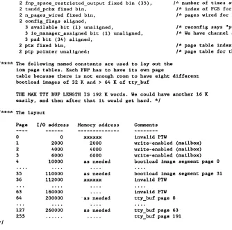
FNP Extended Memory Addressing
Memory
+---+
+--->+
000000-000377Page 0
I
I
I
+---+
I
+--->+
000400-000777 Page 1I I
I I
I
i
+---+
I I
+--->+
001000-001377Page 2
Page Table
I I I
+---+
I I I
4000
I
A=O+- ---+
I I
+---+
I I
4001
I
A=O+---+
I
+---+
I
4002
I
A=O+---+
+---+
+---+
!
I I
I'
+---+
+--->+
076400-076777I
I
Page 175+---+
I+---+
4175 I
A=O+---+
+---+
4176
A=l+---+
+---+
4177
A=l+---+
+---+
077000-077377 Page 176
+---+
077400-077777 Page 177, end of 32K
+---+
100000-100377
Page 200, start extended mem
+---+
+--->+
100400-100777Page 201
MCS Overview
+---+
+---+
+--->+
177000-177377 Page 376+---+
177400-177777 Page 377, end of 64K
+---+
FNP Hardware Description
FNP Address Calculation Example 1
Reference To Address In Low-Order Memory Using Non-Paged Addressing
c (x2)=076700; c(x3)-077240;
~ c(47S)=004000; '\. " c(417S)=000000;
'7 ~\ Ii.e S. .... -IclJ(,! s.~
er
.po,~"(l ",\",131~I
+---=-=--====---~-==---=--~~---+
2 0 7 0 0 1
010 000 III 000 000 001
I
I
000000001
y{
001 --
I
c(4176)=133040
+---+
+---=---=---~---+\ / \ / Final Address
I 1 _ _ _ _ _ _ +- - - -= - - - ---+
1 0 7 6 7 0 1
V
+--==---=---+
+---+
I
I
X-register 2I
+---+
I
1 0
I
7 6 7 0 0I
I
I
I
I
000i
III 110 III 000 000I
+--==---=---=---+
I
I
TagI
IS-bit addressI
I
1
I
1---=-==--=--i
a
I
76700I
+---~-=----+
FNP Hardware Description
FNP Address Calculation Example 1
Reference To Address In Low-Order Memory Using Paged Addressing
c (x2)=076700; c(x3)=077240; c(475)=004000; c(4l75)=000000; c(4l76)=133040
+---+
Instruction: Ida 1,2
+---+
2
a
7a
a
1 11 I 1 I 1 1 I
1 010
I
000I
III 1 000 1 000 1 001 1+---+
I ITag Opcode Delta
1
I
I
I
I
0I
10I
000111I
000000001I
I !
I
I 0 1 2 I 07 I 001
+---~---+
+---+
\ / Final Address
\ /
I 1
- - - -
+---+
I
V
0 7 6 7 0 1
+---+
+---+
IX-register 2 I
+---+
I1 0 7 I 6 7
a
a
I1 I
I
I I II
I
000 IIII
110I
IIII
000I
000I
i
+---
---+
I
I
Tag IS-bit addressI
I
I
1---, 0 76700
I
+---
---+
Tag Page No. Offset
000 III 110 1 11 000 000
o
175 300+---
---+
\ /
1
V
+---+
Page table entry
@
4175 [c(475) + 175 -> 4176]+---+
o
0 0 0 0 0000 000 000 000 000 000
+---+
1 Page addr mod 2561 IActl
I
I
I
I
I
000 000 000a
I
00I
a
i
00000+---+
FNP Hardware Description
FNP Address Calculation Example 3 Reference To Address In Extended Memory
c (x2)-076700; c(x3)=077240; c(475)~004000; c(4l75)=000000; c(4176)=133040
+---+
Instruction: Ida 113
+---== ---=-=---=-+
3
I
a
7a
a
1I
I
I
I
I
I
I
I all I 000 I III 000
I
000I
001I
+--- ---+
I ITag Opcode Delta
I I
I I
I 0
I
11I
000111 000000001I
I
I
I a I 3 I 07 001
+--- ---+
+---+
\ / \ / Final Address
I 1 _ _ _ _ _
+- ---+
V 1 1 3 I 3 2 4 1
+---+
+---+
I X-register 3
+---
---+
I
0 7I
7 2141
a
I
I II
II
I
000 IIII
IIII
010I
100I
000I
+---
---+
I Tag IS-bit address
I
I a 77240
+--- ---+
+--- ---+
1 Tag Page No. Offset 1 3
I
3 2 4 aI
I
I
1 1 1I
I
I 000 III III a 10 100 000 1 001 I all I all 010 1 100 1 000 I
I
+--- ---+
I 0 176 240 1 001 011 all a 10 100 000
+--- ---+
+---+
\
/
\
/
/
V I ______________ ~/
+---+
I Page table entry
@
4176 1 [c(475) + 176->
4176]+---+
1 3 3 0 1 4 0
1 1 1 1 1 I 1
I
001 I 011I
011I
000 1 100I
000 1+---+
1 Page addr mod 2561 IActl
I I 1 I 1
I
001 all all aI
00 1 1I
00000I
+---+
---\
/---
1---FNP Hardware Description
HSLA
I
High-Speed Line Adapter Emulated in 6670sAll communications lines are connected to HSLAs
Maximum of 32 channels per HSLA
Maximum of 3 HSLAs per FNP => maximum of 96 channels per FNP
HSLAs do much of the work of running a channel, freeing up the FNP's CPU
Set and detect RS232 signals
Interrupt FNP when a signal changes
Read incoming characters into a buffer
Interrupt FNP when action is required
Buffer full
BREAK condition
Interesting character (such as CR, LF, EDT) read
Character Control Table (CCT) tells HSLA what characters are interesting
Does not do echoing
Send buffer of characters to terminal
Interrupt FNP when finished
Old FNPs had HSLAs and LSLAs (Low-Speed Line Adapters)
Channel names
One component for each level of multiplexing
FNP. H/L 99
b.hlOI
FNP . H/L 99 . SUB
I
a.h006.prtl Mother/Daughter BoardsFNP Hardware Description
HSLAs are emulated by Mother and Daughter Boards
Communications lines are connected to daughter boards
Two lines are connected to each daughter board
There are different types of daughter boards for different types of lines
Asynchronous
Autocal1 channels
BSC
I
GllS---HOLC daughter boards only have one line connected instead of two
Daughter boards are properly known as CLAs
I
Communications Line AdapterDaughter boards are mounted on mother boards
MCS Overview
Four daughter boards can be mounted on one mother board
Maximum combined speed of lines on mother board is 72KB
An FNP can have up to 16 mother boards
12 mother boards 4 daughter boards 2 lines
=>
96 lines per FNP4 mother boards are the equivalent of an HSLA (32 lines)
Mother boards are properly known as HMLCs
High-speed multi-line controller
~ I~los\
fV'
~ 0(·'1'i
6 n
~
aSS', ()\ "\-0 \
~\o(f
JrYl'O
T
hr; r~:ro", {'~
,.5
(I6'l (Or'\.c
1.)5)
v~
.
FNP Hardware Description
Mother/Daughter Boards
la.h23l a.h2301 la.h229 a.h2281 la.h227 a.h2261 la.h225 a. h224 1
I CIA I I CIA I I CIA I I CIA I
_I
OA,J~lil"f ~~_I
I_I
I_I
1_
: HMLC
Mf!lJ{..~r ~r;.4,rf
1 ______________________________________________________ __
la.hl07 a.hl061 la.hl05 a.hl041 la.hl03 a.hl021 la.hlOl a.hlOOI
I CIA I I CIA I I CIA I I CIA I
_I I_I I_I I_I I_
I I
I
HMLCI
I
I
la.h03l a.h0301 la.h029 a.h0281 la.h027 a.h0261 la.h025 a.h0241
I
CIAI I
CIAI I
CIA1 I
CIAI
_I
I_I
I_I
I_I
I_
I
I
I
HMLCI
I
I
la.h023 a.h0221 la.h02l a.h0201 la.h019 a.h0181 la.h017 a.h0161
I
CLA I I CIA II
CLA I I . CIAI
_I I_I I_I I_I I_
I
I
HMLC1---la.h015 a.h0141 la.h013 a.h0121 la.hOll a.hOlOI la.h009 a.h0081
I
CLA I I CIA II
CIAI
I CIA I_I I_I I_I I_I I_
I
HMLC
I
---~---I
I
I
la.h007 a.h0061 la.h005 a.h0041 la.h003 a.h0021 la.hOOl a.hOOOI
I
CL~I
CIA I I CLA I I I"'T 1\ II I I I v.un. I
_I
1_1 _ _ _ _ _I_I
I_I
I-HMLC
1---o HMLC = Mother Board
o CIA = Daughter Board
FNP Hardware Description
I
I
I
DIA
Direct Interface Adapter
Connects Multics IOH to FNP 'T " " , .l.V.I.'l
200KBit/sec smart controller
DIA can:
Send interrupts in both directions
Transfer data between memories of FNP and Multics at request of either
MCS does not use all these possibilities, i.e. FNP initiates all data transfers
Can have 2 DIAs per FNP
I
But Multics will view each OIA as a separate FNPFNP Hardware Description
a MCS Manuals
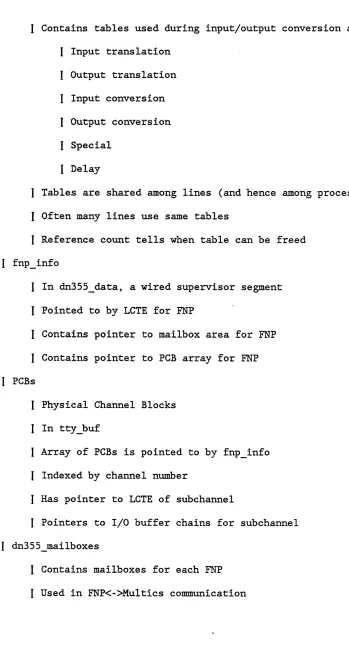
AN8S: Communication System SDN
MCS Internals, both Ring 0 and FNP
Theoretically unavailable: last upc~te MR7.0
CC7S: Multics Administrators' Manual--.Commu:t.:.1ca~ions
AG93: Multics Subroutines and Input/Outptlt Modules'
AG9l: Multics Programmer's Reference Guide
TTF described in Appendix B
Input conversion rules explained in Ch2pter 3
AN87: Hardware and Software Formats PLM
Theoretically obsolete and Unavailable
Chapter 6 has FNP dat~ formats
DDOl: DN3SS/6600 Macro Assembler Program
FIV&'\
MeS Manuals
MCS Administration
& eMF/CDT
Channel Definition Table
CDT describes all configured FNPs, multiplexers, lines
Created from ASCII source file Channel Master File
An Answering Service Database
Stored in >scl>cdt
Used by Initializer to manage lines, logins, etc.
Used to initialize Ring 0 databases at Multics bootload
Ring 0 Databases are not stored permanently
Used to initialize FNP databases at FNP bootload
CMF/CDT
Spare_channel_count: 10;
Sample CMF
Altows
'fOv '\ 0cr.J~
FNP_required_up_time: 5;' \ ~9",\~>
a.\s.o \ ()
\C,"VE'f \~wc\ " - - tb~\~ ~o>S· ~\'\ ~ ~ \t>~.(.yv.,v h';~h"Q{' t (c,.~ \ ~ \. ~ ~~
Check acs: all;
FNP: a· ,
, D\S 'f V\ ( \-.. \ . t' ~
type:
lsla: hsla:
DN6670; \ (;, \Jb\ p,,~ to \<~~f j'T 0.
0; 1'\0 \> CA. ,0 3;
memory: 64;
image: >sldd>mcs>info>fnp_a; service: name: baud: active; a.cOOO; 9600; service: slave;
name: baud:
a.hOOO; 1200; service: mc;
name: baud:
a.hOOl; 1200; service: login;
name: a.h002;
baud: 1200;
service: login;
name: baud:
a.h003; 1200; service: login;
comment: "COLTS executive channel"; line_type: COLTS; terminal_type: none;
comment: "console pupitre";
line_type: ASCII; terminal_type: ROSY; attributes: hardwired,dont_read_answerback;
comment: "console datanet";
line_type: ASCII; terminal_type: ROSY; attributes: hardwired,dont_read_answerback;
comment: "AJ5l0 dans salle de consoles 125"; line_type: ASCII; terminal_type: AJ510; attributes: hardwired,dont_read_answerback;
comment: "AJ860 dans salle de consoles 121"; line_type: ASCII; terminal_type: AJ860; attributes: hardwired,dont_read_answerback;
/***
a.h006 is X.25 Sync HOLC daughter. This board steals a.h007 as well.*/
name: a.h006;
comment: service: multiplexer_type: baud: terminal_type: line_type:
"X.25 canal principal 113001300"; multiplexer;
x25; 9600;
X25_TRANSPAC; X25IAP;
name: a.h006.dOl-a.h006.d02;
service: autocall;
generic_destination: "transpac";
comment: "X.25 dial_out sub-channel";
name: a.h006.00l-a.h006.0l3; .
login; service:
comment:
terminal_type:
MCS Administration
"X.25 login sub-channel"; ascii_crt;
CMF/CDT
baud:
attributes:
1200;
dont read_answerback;
name: a.hOOS; comment: "connexion stations HASP";
baud: 4S00; line_type: BSC; terminal_type: HASP_HOST;
mUltiplexer_type: hasp;
service: multiplexer; attributes: Ahardwired;
name: a.hOOS.opr; service:
line_type: terminal_type:
name: a.hOOS.rdrl; service:
. line_type: terminal_type:
name: a.hOOS.prtl; service:
line_type: terminal_type:
name: a.hOOS.punl; service:
line_type: terminal_type:
slave; BSC;
HASP_HOST;
slave; ESC;
HASP_HOST;
slave; BSC;
HASP_HOST;
slave; BSC;
HASP_HOST;
name: baud:
a.hOlO; 4S00; service: login;
comment: "Questar dans Ie bureau Adjemian-Weberl1; line_type: ASCII; terminal_type: VIP7205;
attributes: hardwired,dont_read_answerback;
CMF/CDT
CMF delivered in >udd>sa>a
Global key-word
2 crashes in this time => no reload
Applies to lower-level multiplexers as well
Global keyword
Number of extra entries in ring 0 databases
Adding CDT entries for which there is no room in ring 0 databases causes problems
Other global keywords
Define default values for omitted local keywords
FNP:
One FNP statement for each configured FNP
Followed by information about the FNP
type:
I
dn6670 memory:I
Memory size in Kwords hsla:Number of HSLAs: can always say 3
Must have one line declared on HSLA 0 before using HSLA 1
Likewise for HSLA land 2
image:
I
Pathname of image to load in FNP service:I
active or inactiveCMF/CDT
name:
One name statement for each configured channel
Followed by information about the channel
Can have a range of channel names, e.g. a.h006.001-a.h006.016
comment:
Comment stored in CDT
Not like /* comments */ which are ignored in CMF
Important to use comments to document
Also important to have well-organized CMF
baud: ~~5
Up to 19.2KB for async, 72KB for sync
110, 133, 140, 300, 600, 1200, 1800, 2400, 4800, 7200, 9600, 19200, 40800, 50000, or 72000
line_type:
fll'ft'c..
Line protocol: ASCII, Gl15, BSC, VIP, POLLED_VIP, or X25LAP
Cannot be changed by user
service:
login
Loaned to process for duration of process
Initializer owns all lines
slave
I
mcLoaned to existing process, returned when finished or at end of process
Requested by sending wakeup to Initializer (using dial_manager_)
Example: Used by I/O daemons to attach printers, readers,
-y~tc.(6.V\: , 0 o..l7J .... (..L.. }Iy_ b,~J{(
I
Like slave, but for the Initializer's own useCMF/CDT
I
Used for operator terminals autocallLike slave, but Initializer makes requested phone or network connection before loaning it
I
Example: dial out .. l' n.;r""",oY\~- \ fL~\.ft.,J &t- V).tI,\e ~AI
'c>
vseA 0\),,;- -f....:::rS,0
(O'f'f'fJC) 0,-inactive
Not listened to when FNP boots
Useful for holding a spot for a line that is not yet physically installed
multiplexer
Line is a mUltiplexer channel
mUltiplexer_type statement must be used as well
multiplexer_type:
ibm3270, vip7760, hasp, x25, or sty
dataset_type:
Used mostly for half-duplex-modems
Require special handling of RTS, CTS, etc.
terminal_type:
Can be changed dynamically by user
For mUltiplexer, TTF entry gives multiplexer-specific parameters in the additional info field
generic_destination:
Valid for autocall and slave lines
Allows users to attach line without knowing channel names
Useful to group together channels, allow changing channel assignments without affecting users
charge:
Specifies a surcharge for using the channel
For login lines this is in addition to connect charges
CMF/CDT
I
Must correspond to device type in installation parms check acs:ACS Segments in >scl>rcp
I
E.g. >scl>rcp>a.h001.acsKeywords specify when access checking is to be done
login
slave
priv attach
dial in
dial out
all
Default is priv_attach, dial out
attributes:
hardwired
Eliminates use of the login_time parameter in installation_parms
set modes
Modes are set according to default terminal type at dialup
Only attribute that is on by default
dont read answerback
System does not send ~E (ENQ) at dialup to request terminal's answerback
check answerback
I
See answerback statement auditSee access class statement
none
CMF/CDT
Default is
set_modes, A audit , A check_answerback , Adont_read_answerba ck,Ahardwired
answerback:
Specifies expected answerback for terminal
I
If check answerback attribute is set~ any other answerback will be refused connectionaccess class:
Specifies the AIM classes of users allowed to login on the line
Enforced if the audit attribute is set
initial command:
Preaccess command (e.g. login, modes, ttp~ etc.) to be executed at each dialup
cv cmf
Converts CMF into CDT
Usually CMF.cmf -> CMF.cdt
Resulting segment has same format as >scl>cdt but with no dynamic information
install
Initializer is the maintainer of COT
Sends a request to Initializer
Initializer merges dynamic info from existing COT with info from new COT
Requires access to >scl>admin acs>cdt.install.acs
Adding, deleting, changing channels
Many CMF changes do not take affect immediately
Some require FNP reboot to take affect
Tables 5-1 and 5-2 in CC7S explain when changes take effect
Most important are adding lines and changing speed of lines
Require FNP reboot
CMF/CDT
Two commands for displaying information from CDT
display_cdt
I
Gives detailed information on CDT entriesI
Gives brief information on eDT entriesreset cdt meters resets n_dialups, n_logins, dialed_up_time
CMF/CDT
CDTE at 515115360
in use: name: comment: charge_type: service_type:
current_service_type: dim:
line_type: terminal_type: baud rate:
fnp_no:
flags.attributes: event:
tra_vec: count: twx: state:
current_termina1_type: cur_line_type:
tty_id_code: process: next channel: n_dia1ups: n_logins:
dialed_up_time: dialup_time:
recent_wakeup_count: recent_wakeup_time:
3 (dialed) achl14
DKU7102 sur sous canal mpx trt de Paris2
o
(none)1 (login)
1 (login)
1 (tty)
1 (ASCII)
DKU7102 1200 1 (a)
hardwired,dont_read_answerback,check_acs;
000470001164407777000107 3 (wait_login_line)
1 46
5 (dialed up)
AJ510 1 (ASCII) none
7777711
o
393 348 1083 hrs
02/20/84 1
02/20/84
CMF/CDT
45 mins 11 secs.
1727.4 hfh Mon
1807.9 hfh Mon
Values for tra_vec in display_cdt output and WP column in tty_lines output
1 wait_dialup 2 wait answerback 3 wait_login_line 4 wait_login_args 5 wait_old-password 6 wait_password 7 wait_new_password 8 wait_logout_sig 9 wait_logout 10 wait_logout_hold 11 wait detach 12 13 14 15 16 17 18 19 20 21 22 23 24 25 wait_new_proc wait remove
wait_fin_priv_attach wait dial release
-
-wait dial out
-
-wait_hangup
wait_slave_request wait_greeting_msg wait delete channel
-
-wait_connect_request wait_tandd_hangup wait fin tandd attach
-
- -wait_discard_wakeups wait_before_hangupChannel waiting for dialup.
wau
sent, waiting for replyGreeting typed, wait for login command. Want rest of login line
"-cpw" was specified. Wait for old password.
Waiting for password. (If "-cpw", repeat of new one.) "-cpw" was specified. Wait for new password
Channel is hooked up. Wait for logout.
A logout has been requested. Wait for process to die As above but don't hang up when it dies.
As above but ignore channel afterwards. As above but make new process and continue. As above but completely expunge channel. When channel dials up, connect it to user Waiting for master process to release. Waiting for auto call to complete
Wait for the hangup event to occur for a channel Ignore line until someone asks
Print greeting message and wait for login line
Channel deleted - mark cdte after process is destroyed logged in; awaiting request re disconnected processes when channel hangs up, proceed with t
&
d attachment when channel dials up, finish t&
d attachmentdisregard all wakeups on channel
allow output to print before hanging up
Values for state in display_cdt output and S column in tty_lines output
-1 masked 1 hung
0 1 2 3 4 5 6 7
2 known 5 dialed
free hung up
listening dialed logged in logged in dialing dialed out
& proc
MCS Administration
Terminal channel is there, but masked by MCS Terminal channel is there, but dead.
Channel being "listened" to, awaiting dialup. Channel is dialed up. This is normal state.
Values for in_use in display_cdt output and A column in tty_lines output
Entry is empty.
Entry is usable but tty is hung up. Entry is waiting for phone call.
Entry is connected but login not complete. Entry is logged in but no process.
Entry has a valid process.
Entry (auto_call line) is dialing Entry (auto_call line) is in use
CMF/CDT
tty_lines
Attached lines - 132 (size - 136) at 02/20/84 1817.0
a.cOOO a.hOOO a.hOOl a.h002 a.h003 a.h006 a.h006.dOl a.h006.d02 a.h006.d03 a.h006.d04 a.h006.dOS a.h006.001 a.h006.002 a.h006.003 a.h006.004 a.h006.00S a.h006.006 a.h006.007 Type (NU) (NU) ROSY AJ510 AJ860 (NU)
ASCII CAPS MINITEL ASCII CRT ASCII CRT ASCII_CRT ASCII CRT ASCII CRT
tty_lines field Name Type No. S yp A Baud User
MCS Administration
'I\."~
.L .. v.
s
~T]? A Baud Usero
5 18 2 9600 COLTS executive channelo 5 0 1 1200 console pupitre
125 5 3 3 1200 console datanet
171 5 6 3 1200 AJSIO dans salle de consoles 12S ISS 5 17 1 1200 AJ860 dans salle de consoles 121
o 0 0 1 1200 X.25 major channel
1649 1 18 1 300 X.25 dial_out sub-channel 603 1 18 1 300 X.2S dial out sub-channel 228 1 18 1 300 X.25 dial out sub-channel 89 1 18 1 300 X.2S dial out sub-channel 38 1 18 1 300 X.2S dial out sub-channel
2788 5 8 5 1200 Desgoutte CNIP2 (none) X.2S login sub-channel 1790 2 1 2 1200 X.25 login sub-channel
1441 2 1 2 1200 X.Z5 login sub-channel 1144 2 1 2 1200 X.2S login sub-channel 910 2 1 2 1200 X.2S login sub~channel 719 2 1 2 1200 X.25 login sub-channel 587 2 1 2 1200 X.25 login sub-channel
display_cdt field name: current_terminal_type: n_dialups: state: tra vec: in use: baud: comment:
CMF/CDT
a FNP Images
An FNP image is the software to load into the FNP
It consists of 'object decks' of individual programs bound together by the bind_fnp command
Two FNP images are delivered in system libraries
>unb>mcs
>unb>site mcs
When the FNP is booted (during Multics bootload or by operator command or after FNP crash) this software is sent to the FNP from Multics
Before loading, configuration information from the CDT is patched in
An FNP's image must contain all software necessary to run the types of lines configured on the FNP
An image should not have unneeded software
I
This would waste FNP memory that could be used for I/O buffers Choosing the necessary modules is the main work in creating an imageI
All software must fit in <32KThe site mcs and mcs images contain software for several types of lines
Sites create their own FNP images tailored to their FNP line configurations
Often have a different image for each FNP
i
Image is stored in a segment whose pathname is specified in CDTFNP Images
Module Name
dia man interpreter scheduler utilities
init
control tables hsla man
trace meters mclt
gllS_tables bsc tables x2S tables hasp_tables vip_tables
polled_vip_tables
(
ibm3270 tables acu tables autobaud_tables
I ic_sampler
!
breakpoint_man\ console man
~
,.wlf.t\~"f.'<~
(0.'"
~~ jO~1t
Of
Needed if:
always always always always always
FNP MODULES
line_type: ascii; hsla: >0;
module: trace; meter: yes; line_type: COLTS
line_type: gllS line_type: bsc; line_type: x2Slap; mUltiplexer_type: hasp
line_type: vip
line_type: polled_vip line_type: bsc; + ibm3270_ service: autocall;
baud: auto;
debug_fnp ic_sample debug_fnp breakpoints console: yes;
Which should happen:
always always always always always always always sometimes sometimes sometimes sometimes sometimes sometimes sometimes sometimes sometimes rare rare rare
(Level-6 remotes) (HASP, IBM remotes) (real Multics x.2S) (HASP)
(Sync VIPs)
(Polled sync VIPs) (3270 controller) (non-x.2S dialout)
(?r-oC~S> C"'-'" \\}-.. (o,,~o'~r <?U"(
3)(o'~-FNP Images
The bind_fnp command uses a control file with .bind_fnp suffix to select software modules to put in FNP image
FNP Images
/*
bindfile for MCS, Multics Communications System */version: 6.Sd;
0;
Isla:
hsla:
memory: console: printer: meter:
~L; (O«!,,~{>o
... j ' \ 6C~\) O'''''t''f'\fv\>~ \o","~(
no; no; yes;
/* module load list = init module must be last
*/
order: scheduler,
interpreter, control_tables, dia_man,
melt, hsla_man, utilities, trace, bsc_tables, hasp_tables, x2S_tables, meters, init;
/*
entry to init from bootload*/
entry: istart;
/*
table size specifications*/
module: type: size:
module: type: mask: size:
trace; trace;
317777; 2048;
/*
trace enable mask*/
/* mask bits: 0 scheduler I dia man
2 interpreter
3 utilities
4 Isla man 5 hsla man */ end;
FNP Images
bind_fnp
fnp_a.bind_fnp [wd]>*.objdk
I
I
v
- - - -
v
I
v
fnp_afnp_a.bind_fnp ([contents [wd]>fnp_a.search]»*.objdk
I
I
V _ _ _ _ _ _ _ _ V
I
I
V V
fnp_a fnp_a.1ist
FNP Images
LDD Structure
+~~---~---+
I
IddI
+---~-+--~-~-+
+---~~+--=---+ mes
+~==-=--+~-~---+
+---~-=--=-+---=---+
+---+---+ +---+--==--+
source object
+---~=+---~--+ +---+--~=--+
*.s.arehive *.archive
FNP Images
Mes
AdministrationI
I
+---+---+ info
+---+---+
355 macros macros.map355
macros asm site_mcs.bind_fnp
site mes.list mes.bind_fnp
mes.list