The Effect of Dental Implant Design on Bone Induced
Stress Distribution and Implant Displacement
Sahar Fawzi
Assistant Professor Systems and Biomedical Engineering department, Faculty of Engineering,
Cairo University
ABSTRACT
Dental implants have a great role in changing treatment concepts to edentulous ridges. This paper presents a finite element analysis evaluation of the effect of implant design on the stress distribution induced in bone surrounding the implant and on the micro displacement of the implant of a full arch screw retained cantilevered fixed mandibular restoration, in case of immediate loading. Twelve models were simulated, all composed of four identical interforaminal dental implants and a cantilever overdenture. Two design parameters (the implant diameter and taper) were tested while keeping all other parameters fixed. The simulated 12 implants have 3.2, 3.7, 4.7 and 6 mm diameter with 0, 2 and 5 degrees tapering respectively. Vertical and oblique loads were applied on the right premolar and first molar under model restrain. Results revealed that, increasing implant diameter leads to decreased bone induced stresses and also decreased implant micro displacement and so leading to better initial stability. On the contrary, increasing implant tapering increased bone induced stresses and also increased implant micro displacement.
General Terms
Finite Element Analysis in Dental research. Dental modeling.
Keywords
Dental Implants; Implant Diameter; Implant Taper; In vitro stress analysis; Immediate Loading.
1.
INTRODUCTION
The state of edentulism has negative impact on the person. It changes his dietary habits and decreases his social interaction due to speech affection, and senile appearance. Complete dentures had been the only treatment option until the emergence of dental implants. Implants were used to support both fixed and removable prosthesis [1, 2]. The basic technique in using dental implants is to place a fixture in the bone for a period of 3-6 months to insure osseointegration and then add the final prosthesis. This is called a two stage implantation. This is a long period for patients wishing to have good aesthetics’ [3]. Immediate loading, adding the prosthesis immediately after placing the fixture, reduces the clinical steps and eliminates the long period required for osseointegration. This appears to satisfy the patient’s needs but it introduces a great threatening to the bone and the whole structure. In case of structure failure, the patient should pass through several clinical visits to remove and replace the implant [1].
Fixed retained implant prostheses are preferably chosen to give patients the natural feeling of fixed teeth. The fixed restoration has the advantage that it requires interarch space less than the 12 mm limitation of the over denture [4]. Although the structure based on interforaminal implant placement with a posterior cantilever has several clinical advantages, yet the cantilever exerts a bending moment that may affect the underlying bone, the prosthesis and even the implants, especially in immediate loading conditions [1]. Implant design (material, structure and dimensions) is an important factor affecting the implant stability and the stresses generated in its surrounding bone. Variations in implant designs were investigated aiming to achieve better stability, to diminish the effect of shear forces on its interface so that marginal bone is preserved and to enhance osseointegration process [5].
Implant diameter (ID) was reported to be more important than implant length (IL) in distributing stresses to the surrounding bone in case of two stage implantation [6]. Using wider implants allows the engagement of extra surrounding amount of bone, and hence improves both structure stability and induced stress distribution pattern [7]. Implant taper (IT) also plays a role in stress transmission. It was reported that under immediate loading conditions, minimally tapered implants (degrees of implant taper ranged from 2° to 14°) generated the most favorable stress distribution patterns [8].
In this study, the induced stress distribution patterns along with the resulted micro displacements resulted according to various diameters and tapers were investigated.
2.
METHODOLOGY
2.1 Model Construction
software (SolidWorks Corporation, Concord, Massachusetts, USA).
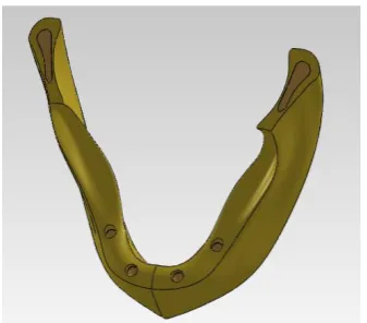
Fig 1: The whole mandible with the circular holes
The obtained measurements (ridge width) of cortical and cancellous bony layers were utilized to draw multiple two dimensional sketches on different planes simulating the conformity of the mandibular body. These sketches were used to obtain the 3D models representing the compact and cancellous bones of half the mandible. The 3D half mandible model comprised of mating the calcellous and the compact bone models, was mirrored to obtain a bilaterally symmetrical mandibular model. Four cylindrical holes with a length of 11.5 mm were cut in the anterior region of the formed mandible model at the expected implants sites, as presented in Figure 1. The created holes have varying diameters to accommodate the various implants used in the different models. The holes were prepared to receive cylinders with inside implant imprint. These bone cylinders represent the peri implant bone.
[image:2.595.376.483.71.176.2]Twelve different implant models were built having a length of 11 mm with diameters of 3.2, 3.7, 4.7 and 6 mm respectively. Each implant exists in three different tapers of 0o, 2o and 5o. A spiral was drawn having 0.6 mm pitch distance and 0.3 mm depth all over the implant body with 15 revolutions. Each implant is connected to the overdenture by an abutment which is attached to the implant through a retaining screw. The retaining screw has 6 mm length and 1.5 mm diameter with a helix of 0.3 pitch and 20 revolutions. Steps for modeling the implant are shown in Figure 2. The implant of a certain diameter and different tapering is represented in Figure 3.
[image:2.595.84.253.96.244.2]Fig 2: Steps for modeling the implant
[image:2.595.329.530.231.368.2]Fig 3: An implant with 3 different tapering of 0o, 2o and 5o The implants receive full arch screw retained prosthesis, as shown in Figure 4.
Fig 4: Model of full arch screw retained prosthesis
2.2 Assigning Material Properties
All the materials used were considered homogeneous and linearly isotropic, so they can be completely identified by Modulus of Elasticity (Young's modulus) and Poisson's ratio. The material properties for compact and cancellous bone of the mandible, titanium alloy of the implant, retaining screw and abutment and the acrylic overdenture were identified and presented in Table 1. The peri implant bone was assigned the properties of the cancellous bone.
Table 1. Material properties for different components [9].
2.3 Specifying Contacts, Boundaries and
Loadings
The contact between the implant and the surrounding bone was identified as slip contact to simulate the immediate
Material
Material Properties
Modulus of Elasticity (MPa)
Poisson's Ratio
Compact bone 15000 0.3
Cancellous bone 1500 0.3
Titanium 110000 0.33
[image:2.595.317.548.512.654.2] [image:2.595.58.277.558.693.2]premolars (50N on each) on one side only, resembling the actual values in case of prosthetic denture.
The vertical load was applied on the central fossa while the oblique load was applied to the buccal incline of the lingual cusps.
2.4 Meshing and Analysis
The models were meshed with a fine solid mesh to create 3D parabolic tetrahedral solid elements. The average element size was set to 1 mm with a tolerance of 0.05 mm.
Linear elastic analysis was performed and von Mises stress (
𝜎
𝑒), the effective stress was used as a measure of the stress state.𝜎
𝑒=
1
2
𝜎
1− 𝜎
22
+ 𝜎
2
− 𝜎
3 2+ 𝜎
3− 𝜎
1 2Where σ1, σ2 and σ3 are the three principle stresses in the three directions
3.
RESULTS
3.1
General Observations on Induced
Stress Distributions
Results showed that, high stresses were induced on the loaded side while negligible stresses were induced on the other side, as shown in Figures 5 and 6.
[image:3.595.326.521.71.217.2]It was also noted that oblique loads induced higher stress values than those induced due to vertical loads.
[image:3.595.315.547.294.648.2]Fig 5: Stress distribution induced in the loaded and unloaded sides
Fig 6: Crestal stress concentration with apical propagation in the loaded side peri implant bone.
3.2
The Effect of Implant Diameter on Peri
Implant Bone Stress distribution
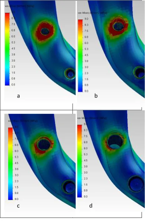
The stress distribution induced in the peri implant bone due to vertical load application, decreases with the increase in implant diameter as shown in Figure 7.
Fig 7: Pattern of stress distribution induced in peri implant bone surrounding implants with different diameters under vertical load; (a). 3.2 mm, (b). 3.7
mm, (c). 4.7 mm & (d). 6 mm.
d c
[image:3.595.55.280.397.546.2]Fig 8: Pattern of stress distribution induced in peri implant bone surrounding implants with different diameters under oblique load; (a). 3.2 mm, (b). 3.7 mm,
(c). 4.7 mm & (d). 6 mm
Table 2 and Table 3 tabulate the maximum stress values, measured in MPa, induced in the peri implant bone due to the application of vertical and oblique loads, respectively.
Table 2. Maximum stress values (MPa) induced due to vertical load
Diameter (mm) 3.2 3.7
Taper 0o 2o 5o 0o 2o 5o
Right posterior 20.7 22.7 27.8 17.2 22.6 24.8 Right anterior 8.1 9.8 10.3 6.5 7 9 Left posterior 1.3 1.6 1.7 1.1 1.2 1.6
Left anterior 1.7 1.8 2.3 1.3 1.4 1.7
Diameter (mm) 4.7 6
Taper 0o 2o 5o 0o 2o 5o
Right posterior 12.3 13.8 16 9 10.4 12 Right anterior 4.6 4.3 5 2.8 3.2 3.1 Left posterior 0.72 0.86 1 0.46 0.52 0.64
Table 3. Maximum stress values (MPa) induced due to oblique load
Diameter (mm) 3.2 3.7
Taper 0o 2o 5o 0o 2o 5
o
Right posterior 26.7 30 35.2 22.3 29.2 33.2 Right anterior 8 9.3 10.6 6.4 7 8.6 Left posterior 2.1 2.2 3 1.6 1.7 2.1 Left anterior 2.3 2.6 3.1 1.7 1.8 2.2
Diameter (mm) 4.7 6
Taper 0o 2o 0o 2o 0o 2
o
Right posterior 15 16.7 15 16.7 15 16.7 Right anterior 3.5 4 3.5 4 3.5 4 Left posterior 0.93 0.9 0.93 0.9 0.93 0.9
Left anterior 0.95 1 0.95 1 0.95 1
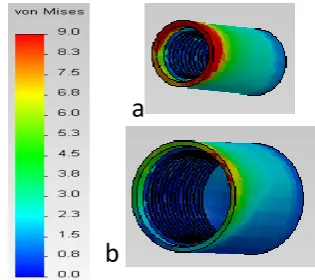
It was also noticed that apical propagation of stresses in the bone cylinder decreased with increasing implant diameter, as shown in Figure 9.
Fig 9: Reduction of apical stress propagation upon increasing the diameter from (a) 3.2 mm to (b).6 mm
3.3 The Effect of Implant Taper on Peri
Implant Bone Stress Distribution
For a certain diameter, an increase in implant taper leads to an increase in apical propagation of peri implant stresses, as illustrated in Figure .10.
a b
c d
[image:4.595.317.541.90.303.2] [image:4.595.344.502.359.499.2]Von Mises (N/mm2
(MPa))
[image:5.595.49.292.69.387.2]Loaded side Unloaded side
Fig. 10: Peri bone cylinder surrounding an implant with different tapering (a) 0o, (b) 2o, (c) 5o.
3.4 Observations and measurements of
implant displacement
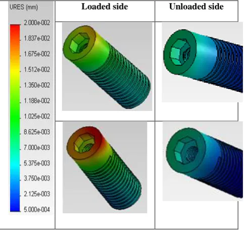
In coherence with stress distribution obtained, the highest micro-movement was recorded at the right posterior implant (highest loaded implant), while implant displacement on the unloaded side showed insignificant values.
The displacement values measured under oblique loads were relatively higher than those measured under vertical loads, as shown in Figure 11.
[image:5.595.314.541.151.359.2]Loaded side Unloaded side
Fig 11: Micro motion of dental implants under vertical (a) & oblique (b) Loads
3.5 The Effect of Implant Diameter on
implant displacement
Maximum measured displacements values (μm) were tabulated in Tables 4 & 5.
Table 4. Values of maximum implant displacement (μm) due to vertical load
Diameter (mm) 3.2 3.7
Taper 0o 2o 5o 0o 2o 5
o
Right posterior 28.6 30.1 35.2 23.7 25.1 28.2 Right anterior 14.1 15 16.5 11.7 12.2 13.4 Left posterior 2.2 2.4 2.8 1.7 1.8 2
Left anterior 3.3 3.6 4 2.9 3 3.4
Diameter (mm) 4.7 6
Taper 0o 2o 5o 0o 2o 5
o
Right posterior 16.7 18 20 12.5 13.3 14.7 Right anterior 8.3 8.8 9.5 6.3 6.7 7.2 Left posterior 1 1.1 1.3 0.7 0.8 0.9 Left anterior 2.2 2.3 2.5 1.7 1.8 2 Table 5. Values of maximum implant displacement (μm)
due to oblique load
Diameter (mm) 3.2 3.7
Taper 0o 2o 5o 0o 2o 5
o
Right posterior 37.9 40.6 45.8 30.9 32.5 36.3 Right anterior 14.1 15.1 17 11.3 11.8 13.1 Left posterior 3.5 3.8 4.4 2.7 2.8 3.2
Left anterior 4.1 4.3 4.8 3.1 3.2 3.5
Diameter (mm) 4.7 6
Taper 0o 2o 5o 0o 2o 5
o
Right posterior 21.3 22.8 25.1 15.8 16.8 18.4 Right anterior 7.6 8.1 8.8 5.7 6 6.5 Left posterior 1.7 1.8 2 1.3 1.4 1.5 Left anterior 2.1 2.2 2.3 1.6 1.6 1.7
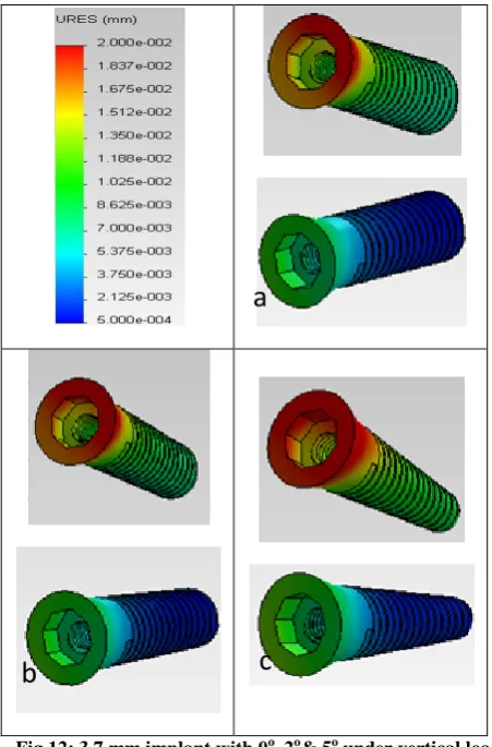
3.6 The Effect of Implant Taper on implant
displacement
[image:5.595.49.291.515.742.2]Fig 12: 3.7 mm implant with 0o, 2o& 5o under vertical load
4.
DISCUSION
The bone shows a dynamic state of resorption and deposition in reaction to stresses below its mechanical yield strength. Determination of the force magnitude that induces resorption is not well established, so it is difficult to claim that a certain stress is totally safe [10].
Applying the force on one side (simulating the normal chewing action), induces high stress values on this side with minimal propagation to the other side because acrylic restoration has the ability to transmit the forces to the underlying abutment/ implant rather than distributing stresses through its whole body, as shown in Figure 4.
The stress values induced in the peri implant bone due to vertical load are lessthan that induced due to oblique load, as indicated by the maximum stress values tabulated in Tables 2 & 3. This is due to the combination of both vertical and shear components in case of oblique load. The vertical load is directly transmitted through the underlaying implant. In both cases the effect of the bending moments of the cantilever is added to the resulting stress distributions.
The loaded side implants bear more stresses on its distal part due to bending moments of the cantilever on the restorations which in turn transfer more stresses to the peri-implant bone at this side. The nature of healing bone allows stress propagation along the bone cylinder permitting relatively more stresses to reach the apex as compared to the healed bone refrenced in [11].
The results revealed that raising the diameter by a factor of aproximatly 1.5 decreases the resulted stress by more than 40%, while doubling the diameter decreases the resulted stress by about 56%, as shown in Table 2. This is due to the findings that wider implants increase stiffness of the implant and also increase bone-implant contact surfaces, allowing the engagement of maximal amount of bone and theoretical improvement of the stress distribution in the surrounding bone.
The results also revealed that increasing implant taper to 2o led to an average of 15% increase in the induced stress values while a taper of 5o would increase the stress induced in the peri bone by an average of 35%, as shown in Tables 2 &3. This may be attributed to the reality that an implant of a certain diameter with 0o tapering has more surface area than its tapered one allowing more absorption of the energy and less transmission of stresses to the surrounding bone. Moreover, on applying vertical loads, the column of forces would be totally recieved by the cylinderical implant and stresses reaching the bone would be minimized unlike the case in the tapered implant where the column of force would be directly shared between the implant and the bone.
The displacement of implants was found to increase with the application of oblique loads rather than vertical loads. As for implant displacement, increaisng the diamter by about 150% (from 3.2 to 4.7), would lead to decrease in implant displacement by 40% while approximatly doubling the implant diameter would lead to 60% decrease in implant displacement, as tabulated in Tables 4 & 5. This is attributed to the idea that wide diameters have broader surface area that
a
b
c
[image:6.595.48.281.419.748.2]implant displacement while a taper of 5o increases implant displacement by around 20%.
Moreover tapered implant has a decreasing cross section till reaching the apex, so unscrewing one thread facilitate implant removal as every implant cross section would be opposed by wider osteotome, leading to decrease in the stability of the immediate loading restoration.
5.
CONCLUSION
The presence of cantilevers resulted in accentuation of bone stresses especially, at the bone distal to the terminal implant. Increasing implant diameter, within limitation of bone anatomy, and decreasing implant taper lead to better stress distribution and to reduced implant micromotion.
6.
ACKNOWLEDGMENT
The author would like to thank Prof. Dr. Mohmoud Elfar, Professor of prosthodontics, Faculty of Oral and Dental Medicine, Cairo University. Dr Azza Farahat , Lecturer of prosthodontics, Faculty of Oral and Dental Medicine, Cairo University and Dr Marwa Abdelaal Faculty of Oral and Dental Medicine, Cairo University
7. REFRENCES
[1] Misch, C.E., “Contemporary Implant Dentistry”, 3rd Edition, Elsevier Mosby, Missouri, 2008. [2] Mericske-Stern, R.D., Taylor, T.D. and Belser, U.,
“Management of Edentulous Patient”, Clin Oral Impl Res; Vol. 1, pp. 108-125, 2000.
[3] Engelke, W., Decco, O.A., De las Mercedes, C.M., Schwarzwaller, W. and Villavicencio, M.M., “Immediate Occlusal Loading of Freestanding Implants Using Cortical Satellite Implants: Preliminary report of a prospective study”, J. Implant Dent. Vol. 14, pp. 50-57, 2005.
[4] Alsabeeha, N.H., Swain, M.V. and Payne, A.G., “Clinical performance and material properties of single-implant overdenture attachment systems”, Int. J. Prosthodont, Vol. 24, pp. 247-254, 2011 [5] Linish, V., Peteris, A., “Dental Implant Design and
Biological Effects on Bone-Implant Interface”, Stomatologija, Baltic Dent and Maxillofac. J. Vol. 6, pp. 51-54, 2004.
[6] Jae-Hoon, L., Val, F., Keun-Woo, L. and Robert, W., “Effect of Implant Size and Shape on Implant Success Rates: A Literature Review”, J. Prosthet Dent., Vol. 94, pp. 377-381, 2005.
[7] Khon, D.H., “Overview of Factors Important in Implant Design”, J. Oral implantol., Vol. 18, pp. 204-219, 1992.
[8] Momen, A. and Reza, A. S., “The Evaluation of Optimal Taper of Immediately Loaded Wide-Diameter Implants: A Finite Element Analysis”, J. Oral Implantol., Vol. 10, 2011.
[9] Elkhadem, A.H., Fawzy, S.A., Ibrahim, A.M. and Elsayed, S.M., ”Implant Tilting Effect on Bone Stresses Induced in Cantilever Mandibular Prothesis”, J. Engineering and Applied Science,.2011.
[10]Geng, J.P., Tan, K.B. and Liu, G.R., “Application of Finite Element Analysis in Implant Dentistry: A Review of Literature”. J. Prosthet. Dent.; Vol. 85, pp.585-598, 2001.
[11]Fawzi, S. A., “Influence of Bar Position on Implant-Retained Mandibular Overdenture A Three Dimensional Finite Element Analysis”, CASBEC, 2012.
[12]Mahon, J.M., Norling, B.K. and Phoenix, R.D., “Effect of Varying Fixture Width on Stress and Strain Distribution Associated with an Implant Stack System”, J. Implant Dent., Vol. 9, pp. 310-320, 2000.
[13]Himmlova, L., Dostalova, T. and Konvickova, S., “Influence of Implant Length and Diameter on Stress Distribution: A Finite Element Analysis”, J. prosthet. Dent. Vol, 91, pp. 20-25, 2004.
[14]Nobuaki, O., Roxana S., Eriko K, Kouichi K., Shuichi N., “Influence of maxillary cortical bone thickness, implant design and implant diameter on stress around implants: A three-dimensional finite element analysis”, J. prosth. Res., Vo, 54, pp