Design and Analysis of Stepped Impedance Microstrip
Low Pass Filter Using ADS Simulation Tool for Wireless
Applications
K.Rajasekaran*, J.Jayalakshmi**T.Jayasankar***
*
Department Of Electronics and Communication Engineering, M.A.R College of Engineering Trichy
**
Department Of Electronics and Communication Engineering, PABCET, Anna University Trichy
*** Department Of Electronics and Communication Engineering, University College of Engineering Anna University BIT Campus Trichy
Abstract- There is an increasing demand for microwave systems to meet the emerging telecommunication challenges with respect to size, performance and cost. This project describes a general design technique for micro strip low pass filters that are used to convey microwave frequency signals. The parasitic problems of X- band can be adjusted through impedance ratio K, which can enhance the performance of harmonic suppression. The ADS simulation tool is used to design an X-band stepped impedance low pass filter of range 8-12 GHz. This simulation results show that the filter works on 10GHz at the center frequency and achieves attenuation of 60dB, which effectively suppresses the parasitic bands. To attain the filter with these characteristics, Insertion Loss Method is performed. Compared to other filter types, this design works very well with excellent harmonic suppression performance.
Index Terms- ADS, Attenuation, Harmonic suppression Insertion loss, Micro strip, Stepped impedance.
I. INTRODUCTION
icro strip is a type of electrical transmission line, which can be fabricated using printed circuit board [PCB] technology, and is used to convey microwave-frequency signal. It consists of a conducting strip separated from a ground plane dielectric layer known as the substrate. Micro strip is much less expensive than traditional waveguide technology, as well as being far lighter and more compact. The disadvantages of micro strip compared with waveguide are the generally lower power handling capacity, and higher losses.
Also, unlike waveguide, microstrip is not enclosed, and is therefore susceptible to cross talk and unintentional radiation. For lowest cost, microstrip devices may be built on an ordinary FR-4 (standard PCB) substrate. However it is often found that the dielectric losses in FR-4 are too high at microwave frequencies, and that the dielectric constant is not sufficiently tightly controlled. For these reasons, an alumina substrate is commonly used. On a smaller scale, micro strip transmission lines are also built into monolithic microwave integrated circuits [MMIC] s.
Micro strip lines are also used in high-speed digital PCB designs, where signals need to be routed from one part of the
assembly to another with minimal distortion, and avoiding high cross talk and radiation. A stripline circuit uses a flat strip of metal, which is sandwiched between two parallel ground planes. The insulating material of the substrate forms a dielectric.
The width of the strip, the thickness of the substrate and the relative permittivity of the substrate determine the characteristic impedance of the strip, which is a transmission line. In the general case, the dielectric material may be different above and below the central conductor to prevent the propagation of unwanted modes; the two ground planes must be shorted together. Most communication systems require an RF front end, where RF filters and low noise amplifiers perform analog signal processing. Micro strip RF filters are commonly used in receivers and transmitters operating in 800 MHz to 30 GHz frequency range. In this project, a design of prototype lowpass filter and its implementation to microstrip line is done and responses are analyzed. Joining together two micro strip transmission lines with different characteristic impedances forms fundamental micro strip low pass filter. The design is performed in Advanced Design System software.
II. DESIGN AND MATHEMATICAL CALCULATION In microwave filters, lumped elements of the of filter circuit sections are simulated by means of waveguides, coaxial lines, strip (or) micro strip lines, cavity resonators, etc. [2].The equivalent lumped elements values of the microwave components are themselves functions of the frequency [2]. There are two design techniques properly used.
1) Image parameter method.
2) Insertion loss method. .
A.
Advantage of Insertion Loss MethodInsertion Loss method complete specification of a physically realizable frequency characteristic over the entire pass and the stop bands from which the microwave filters are synthesized.
B. Low-Pass Design
Basic design of microwave filters of type’s low-pass, band-pass and band-stop, operating at arbitrary frequency bands and
between arbitrary resistive loads, are made from a prototype low-pass design through:
1) Some frequency transformer,
2) Element normalization and Simulation of these elements by means of sections of microwave transmission line,
3) Design of a prototype low-pass filter with the desired pass band characteristics,
4) Transformation of this prototype network to the required type (low-pass, high-pass, band-pass) filter with the specified center and band-edge frequencies.
5) Realization of the network in microwave form by using sections of microwave transmission lines.
[image:2.612.314.566.71.349.2]C.
Flow Diagram to Design a FilterFig 1 Design flow diagram
D. Filter Specifications
III. DESIGNING STEPS FOR LOW PASS FILTER IN ADS STEP.1
We choose order of the filter to be 7, N = 7.
There are two responses to assign prototype values for designing. 1) Butter worth (maximally flat) filter,
2) Chebyshev filter.
For Butterworth response we use the specific formula to determine prototype values. The formula is
Butterworth Prototype Element Values g o = 1
g k = 2sin [(2k-1) /2n], k=1,2,…..,n
g n+1 = 1, for all n
STEP.2: Filter Transformations from Prototype
In order to design actual low pass filters, the transformations of the low pass prototype filters with normalized cut-off frequency, Wc’=1 and having the source and load resistances of
1ohm are made into the desired type with Required source and load impedances using frequency and impedance
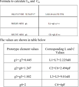
Formula to calculate LK and CK
The values are shown in table below
Prototype element values Corresponding L and C Values g1= g7=0.445 L1=L7=2.225nH
g2=g6=1.247 C2=C6=2.494pF
g3=g5=1.802 L3=L5=9.01nH
g4=2 C4=4pF
[image:2.612.311.571.394.506.2]STEP 3: By Substituting all these L and C values in the network design, we have;
[image:2.612.310.578.537.638.2]Fig 2 Schematic diagram of LPF using L&C values in network
Fig 3 Schematic diagram of LPF with S parameters
Schematic diagram of LPF using L&C in network with S-parameter. The design is being synthesized and “display window” is being created.
Output waveform of LPF using lumped elements Response type Butterworth (or)
maximally flat Centre frequency 10GHz Stop band attenuation -60db
Source and load impedance
Fig 4 Output Wave form S parameters vs Frequency
This is the prototype low pass filter response where the attenuation property is not satisfied here. Hence we go for micro strip implementation.
STEP 4:
Filter designs beyond 500MHz are difficult to realize with discrete components because the wavelength becomes comparable with the physical filter element dimensions, resulting in various losses severely degrading the circuit performance. Thus to arrive at practical filters, the lumped component filters must be converted into distribution element realizations.
In order to convert lumped components to micro strip lines of various impedances should be found out hence we go for
1) Richards Transformation 2) Kuroda Identities
RICHARDS TRANSFORMATION:
To accomplish the conversion from lumped and distributed circuit designs, Richards proposed a special transformation that allows open and short circuit transmission line segments to emulate the inductive and capacitive behavior of the discrete components [1].
Richards transformation allows us to replace lumped inductors with short circuit stubs and capacitors with open circuit stubs of characteristic impedance Zo= 1/ C.[1] Thus from prototype series inductance are the same and shunt capacitance is replaced by 1/ C values.
Formula for Electrical Lengths
Β l l = g x * R0 / Z h
Β l c = g x* ZL / R 0
After substitution the Results after Richards Transformation and Kuroda Identity as shown table below
Impedance with 50 ohm not
considered
Impedance with 50 ohm considered
Electrical lengths (Degree)
Z1=Z7=1.445 72.25 17.64
Z2=Z6=0.8019 40.095 57.29
Z3=Z5=3.247 162.35 31.79
Z4=0.5 25 57.29
Step 5: LINE CALC
[image:3.612.316.539.247.403.2]With having the impedance and electrical length of the stub lines, the width and length of the line can be calculated using linecalc tool in schematic window as shown in Fig 5.
Fig 5 Line Calculation Tool
Thus for each inductance and capacitance line width and length is calculated using linecalc as shown in table.
IMPEDANCE (OHM)
ELECTRICAL LENGTH (DEGREE)
WIDTH (MIL)
LENGTH (MIL) Z1=Z7=72.25 17.64 10.359 22.996 Z2=Z6=30.09 57.29 37.975 70.4118 Z3=Z5=162.35 31.797 0.3255 43.4755 Z4=45 57.29 80.104 61.1688
Fig 6 Schematic diagram of LPF using Micro strip
[image:4.612.36.272.264.454.2]For the above schematic, the layout can be given as follows.
Fig 7 Layout of LPF using Micro strip
III. INFERENCE
Thus we get sharpest attenuation of -60 db. using insertion loss method and cut off frequency of 9 GHz app. to 10 GHz. Hence, the filter allows to pass the frequencies less than 10GHz and rejects those frequencies more than that.
S (1,1),S (2,2) = scattering matrix for return loss.
S (2,1) = scattering matrix for insertion loss.
IV APPLICATION OF MICROSTRIP LOW PASS FILTER
Wi-Fi is a wireless LAN technology that enables laptop PC’s, PDA’s, and other devices to connect easily to the Internet. Technically known as IEEE 802.11 a/b/g/n. Wi-Fi is less expensive and nearing the speeds of standard Ethernet and other common wire-based LAN technologies. Several Wi-Fi hot spots have been popular over the past few years. Some business charge customers a monthly fee for service, while others have begun offering it or free in an effort to increase the sales of their goods.
V.CONCLUSION
In this paper, stepped impedance micro strip low pass filter is designed. This filter provides us to achieve better harmonic suppression. This filter not only shows a superior harmonic suppression in stop-band, but also saves as much compact circuit size compared with the conventional one. This design is applied in X-band electromagnetic environments. Various steps to design a stepped impedance micro strip filter are described. The special calculator, linecalc of ADS is used for designing. The calculated filter parameters are applied to design a filter. The software platform used in this designing purpose is ADS (Advanced Design System). This software is used especially in leading industries working on MMIC’s. A filter of mentioned specifications is designed. The corresponding waveforms are obtained. The range of attenuation achieved can be known from the waveform. Then the layout of the designed stepped impedance micro strip filter is obtained using the software itself. Thus, finally a stepped impedance micro strip filter whose harmonic suppression is -60db is obtained.
REFERENCES
[1] M.Pozar, “Microwave Engineering “ 4 th Ed. Wiley, Ed. pp. 388–422. [2] Annapurna Das, Sisir K Das , “Microwave Engineering ”Tata McGraw-Hill NewDelhi. Pp. 275-289.
[3] Binong*,QuanyuanFeng,Shuai Yang” Research and Design of X-band SIR Microstrip Filters “ IEEE Explorer2009 .
[4] ApisakWorapishet,,Kunnthphong Srisathit, Wanlop Surakamponton,“Stepped Impedance Coupled Resonators For Implementation Of Parallel Coupled Microstrip Filters With Spurious Band Suppression,”IEEE Trans Microwave Theory and Technique Volume 60 June 2012.
AUTHORS
First Author – K.Rajasekaran (Correspondent Author)
Assistant Professor Department Of Electronics and Communication Engineering, M.A.R College of Engineering and Technology, Email:mvkraja@yahoo.com.
Telephone: 09080009439.
Second Author – J.Jayalakshmi, Department Of Electronics
and Communication Engineering, Anna University Trichy Email. san.jayalakshmi@gmail.com Telephone: 08695046034
Third Author – T. Jayasankar. Assistant Professor