1745
IMPLEMENTATION OF WIRELESS COMMUNICATION
SYSTEM USING NETWORK CODING ON WARP
1
ENDROYONO, 2SUWADI, 3ACHMAD ANSORI, 4UMMUL KHAIR
1,2,3,4
Department of Electrical Engineering, Institut Teknologi Sepuluh Nopember (ITS)
SURABAYA, INDONESIA, 60111
E-mail: {1endroyono,2suwadi, 3ansori}@ee.its.ac.id, [email protected]
ABSTRACT
Mobility is one of the most interesting assets in modern communications. The need of a very fast data access in wireless communication is become a necessity. It is obligatory to have a good throughput in a wireless limited bandwidth. In this paper we propose to implement a combination of Network Coding and Quadrature Amplitude Modulation (called NC-QAM), started by a simulation and followed by a realization in a Wireless Open-Access Research Platform (WARP) module. Our model consists of two sources and one relay and one receiver. Based on an analytical simulation, theoretically we found that the combination of C-QAM gives us a throughput improvement up to 31.8% compared to C-QAM without network coding. Based on the same model, the implementation on WARP has been carried-out. Two measurements and evaluations have been performed, with indoor and outdoor channel, by considering distance between two different sources. The evaluation shows that the improvement of combination NC-QAM can reach 14.02% compared to a system without network coding.
Keywords: Network Coding, Quadrature Amplitude modulation, throughput, wireless Open-Access
Research Platform.
1. INTRODUCTION
Telecommunication technology is major aspect in ICT era. On that era, Wireless communication systems are becoming important of telecommunication to give a very high mobility society. For this purpose, the system should be a high capacity, fast data access, high reliability and high security. Some efforts, included source coding, channel coding, and data security coding have been developed to gain high throughput with the best probability of error.
A model called "Network Information Flow," which was inspired by the application of computer networks have been also used in wireless communication system. The model focuses on the use of some point-to-point communication basis, in a multicast way or a combination. The model considers that information as “fluid”, so we can re-created and re-directed the flow easily. The flow control is applying on the network’s node, so it calls a “Network Coding” [1]. By this coding, we expect to have acceptable coding rate and to save the bandwidth.
In The research previous, it was implemented cooperative communication system using WARP
and it was evaluated its performance[2]. It also has been implemented an OFDM system and MIMO system on WARP[3-4]. The systems were not improved their throughput. In this study, we are interested in a model built from a very basic form of modulation, the Quadrature Amplitude Modulation [5]. We have implemented this technique in our WARP platform prior to development of our NC-QAM Model. NC-QAM stands for the combination of Network Coding and QAM modulation. By combining NC and QAM in a WARP platform, an improvement of network’s throughput and data reliability may be achieved [6]. The choice of WARP Platform is based on the fact that WARP Platform categorized as a platform that can implement algorithms wireless very complex [7].
1746
2. SYSTEM MODEL
2.1 System model of QAM Modulation
In digital communication, the transmission of digital data in the media (under water, air, wire, coaxial cable, waveguide, or a group of optical fibers) should pass through a modulator. Modulator will process base-band digital information to an analog form of a carrier signal. Usually the carrier will have a frequency higher than the base-band frequency, and varying in amplitude, frequency or phase [5]. The most questions during the modulation process will be the bandwidth efficiency of modulation (bps/Hz), the capability to
adapt the transmission channel, and complexity of receiving part.
[image:2.612.101.501.248.698.2]Some time it is important to have theoretical efficiency of 1bit/Hz in maintaining the robustness of system in channel and a non-complex system. And, it is also possible to have modulation with M-Ary digital methods to achieve higher symbol efficiency than 1 bit/Hz. In this paper, we propose to use a QAM [5], which have 2 bit/symbol. In our model, each symbol will be transmitted via two modulated signal, real part in I channel (in-phase) and imaginary part in Q channel (Quadrature).
Figure 1: QAM transmitter system block [8]
Figure 2: QAM receiver system block [8]
Serial to parallel converter
LPF
cos wct
LPF Delay Tb
BPF
90
X X
X Binary data
IN
F1 = Fb/2
Q
QAM output
X
X Cos wct
-90 0
LPF
LPF QAM Input
I
[image:2.612.109.496.273.455.2]1747 To realize the above QAM scenario, binary data with a rate of 1/ bps, will be split by a serial to parallel converter into two binary data sequence and transmitted in parallel with a rate of 1/ bps, 2 . refer the symbol rate or baud rate, and is the bit rate. Then the low pass filter is used to limit the bandwidth of baseband signal and to form the signal suitable to carrier used. Since we use Amplitude Modulation System, the data signals of I channel and Q channel are modulated using modulation DSB-SC. I channel will be modulated directly to carried signal (cos , so called in-phase. The carrier for Q-channel will be shifted 90° prior to modulator, so called quadrature channel. The result of I-Q modulator is then summed and filtered using band-pass-filter (BPF) in order to limit the bandwidth spectral in pass-band domain. The QAM modulation-demodulation processes are shown in Figure 1 and Figure 2.
2.2 Network Coding
In the existing computer network, each node serves as a switch in the sense to forward any information from an input link to an output link. The node may copy the information received from an input link and send it to a predetermined output link. From the Information theoretic (Information Theory) standpoint, there is no reason to limit the functions of a node into the switch. It is better to consider a node to function as an encoder in the sense node receives information from all the input links, encode, and send information to all output links. From this view point, a switch is a special encoder. Furthermore, it will all lead to coding at a node on a network, and referred as Network Coding [1]. Our scenario is described as following.
1) Non-Network Coding Schema [6]
By assuming the system works without the use of network coding, and a basic configuration is intended to avoid interference, a “four timeslot” is required to exchange two consecutive packages, one at each destination. Figure 3 illustrates the process of exchanging the two packages. At timeslot 1, node 1 sends a packet to relay R. in timeslot 2, relay R forward packets to node 2. In timeslot 3, node 2 sends a package to relay R. And in timeslot 4, relay R forwards the packets
[image:3.612.315.523.50.181.2]to node 1..
Figure 3: Traditional non-network coding scheme [6]
Figure 4: Straightforward network coding scheme [6]
2) Straightforward Network Coding Schema Straightforward network coding scheme is performed by reducing the number time-slot, i.e. three time-slot from the previously four timeslot. This scheme resulted in throughput improvements of 33% of the non-network coding scheme [6].
In Figure 4 illustrates a schematic of a straightforward network coding. At timeslot 1, node 1 sends a packet to relay R. on timeslot 2, node 2 sends a packet to relay R. After receiving the package and , relay R create a package
, . In general, some mapping of network coding , is possible. Formula , is an XOR operation, expressed as follows:
⨁ (1)
Where the pair XOR symbol ⊕ states per symbol of package and . At timeslot to 3, relay R is broadcasting to node 1 and node 2. At node 1 receives information from , extract information from using information from . So it can be written as follows:
⨁ ⨁ ⨁ (2)
Like-wise on node 2, extract information of
⊕ [3]. Diagram of Straightforward Network Coding Scheme process is depicted in Figure 5.
3) Throughput [6]
Throughput analysis is based on the calculation time slot, assuming the number of any sent will be received correctly.
Time Slot 1 Time Slot 2 Time Slot 3 Time Slot 4
1 R 2
S1 S1
S2 S2
Time Slot 1 Time Slot 2 Time Slot 3
1 R 2
S1 S2
[image:3.612.319.521.206.270.2]1748
Figure 5: Straightforward network coding schema block [9]
Figure 6 Blok of simulation process for M-QAM communication systems with network coding
2.3 The Working Principle of the System
2.3.1 Design of System Simulation in MATLAB
Before implementing the system, the system is tested by simulation. These simulations serve as a starting-point of the system implementation. The model consists of two sources, as the origin. It is
connected to destination nodes are connected by a relay. So that the communications system simulation process M-QAM with Network Coding is depicted in Figure 6. Each block in the simulation represents to signal, bits or symbols pass through the block.
Generate Bit Serial to Parallel
Biner to Decimal QAM Modulation
Receive Bit Parallel to Serial
Decimal to Biner QAM
Demodulation
Generate Bit Serial to Parallel Biner to Decimal QAM Modulation
XOR Bit S1 and S2 Serial to Parallel Biner to Decimal QAM Modulation
S1 TX
S2 TX
Relay
QAM Demodulation Decimal to
Biner Parallel to
Serial
Receive Bit XOR SR with S1
S1 RX
QAM Demodulation Decimal to
Biner Parallel to
Serial
Receive Bit XOR SR with S1
[image:4.612.102.535.382.617.2]1749 At the beginning of each node, S1 and S2, randomly generated bits of information, a row of bits can be expressed as
1 , 2 , 3 , … , (3)
For, n is lots of randomly generated bits. Serial bit stream is then shaped into a parallel bit stream as much as k parallel, with the M-QAM constellation size and can be expressed as:
! "
# (4)
Parallel bit stream is further grouped into a binary symbol. In MATLAB 2013b, modulated symbols in the form of a decimal symbol. Hence, the binary symbol is converted into a decimal symbol first and then modulated with QAM modulation.
In the simulation program, the channels used are AWGN channel. AWGN channel is to replace the channel condition at the time of implementation.
Signals from S1 and S2 are sent to the relay. After at the receiver relay, the signal that has gone through AWGN channel demodulated by the QAM demodulation. Demodulation results converted back into binary form and the back row of parallel binary formed into a serial bit stream. This serial bit stream is a bit of information sent from the source node S1 and S2.
The bit of information that has been received and network coding process is then performed, as described in [6] bits of information S1 and S2 in-XOR. The Results of XOR broadcast to S1 and S2 with the same delivery process as senders S1 and S2.
In S1 and S2 receiver, the signals relay information from the demodulated. Decimal symbol of the demodulation result is converted back to a row of parallel binary and then formed into a row of serial.
In the node S1, bits of information received from the relay in-XOR of the bits of information
belonging to the node S1 is sent to the node S2 to get bits of information from node S2. The same process is also performed in the node S2. But at the node S2 bits of information from the relay OR with bits of information belong to the node S2. Figure 7 shows of the simulation results.
From Figure 7, there are simulation results of QAM Relay. Relay QAM question are relay communication system with 4 QAM, but without network coding is added to the process. Figure 7 shows the BER is the ratio between the relay communication system with and without network coding. The simulation results will serve as starting point in the implementation of the system.
Figure 7: The result of simulation BER at 4-QAM relay and 4 QAM with network coding
2.3.2 Implementation system at WARP module
In the implementation phase, the specific programming code is written. The program is different from program written during simulation phase. WARP includes some modeling tools, can be used along with the system parameters planted for WARP platform based in the system to be implemented. So it is necessary to re-design the system form algorithmic to physical code for WARP. The working process of the system illustrated in the block diagram in Figure 8, and Figure 9.
Figure 8: Block process at transmitter
Generate Bit QAM
Modulation Add Pilot Upsample Add Preamble
Filter SRRC Upconvert
1750
Figure 9:.Block of process at receiver
3. MEASUREMENT&ANALYSIS
3.1. Measurement of system
Measurement system implemented WARP is done on 4-QAM constellation. The measurements are taken at two different conditions, the conditions in indoor and outdoor conditions with different distances. The measured parameters include Bit Error Rate (BER), Throughput, and constellation diagram. From these measurements can be used as a scenario analysis of the comparative performance of the communication system network coding.
3.1.1 Indoor Environment
Measurement with the conditions in the room is carried out in AJ403, The Laboratory of Basic Telecommunication Systems, Department of Electrical Engineering ITS. The third node is placed in the position of a straight line. Setting distance variation is applied to the distance between the node 1 and node 2. Node 1 and node 2 is at once a source node destination node, while the node is a relay node that connects the communication path between the first node and the second node in the communications relay and network coding. Configuring the location and distance for each node its depicted in Figure 10.
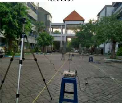
3.1.2 Outdoor Environment
[image:6.612.319.517.416.582.2]Measurements with outdoor conditions carried out in the parking lot for lecturer of the Department of Electrical Engineering ITS. The third node is placed in the position of a straight line. Setting distance variation is applied to the distance between the node 1 and node 2. Node 1 and node 2 is at once a source node destination node, while the node is a relay node that connects the communication path between the first node and the second node in the communications relay and network coding. Configuration of the location and distance for each node it’s depicted in Figure 11.
Figure 10: Configuring of each node WARP for indoor evironment
Figure 11: Configuring of each node WARP for outdoor evironment
Figure 12 illustrates the result curves of simulation: Bit Error Rate (BER) of the Signal to Noise Ratio (SNR) at the 4-QAM. In the simulation, the channel used for simulation is the Additive White Gaussian Noise to Signal (AWGN). As the results of the value of BER on 4-QAM with network codingis are better than the value of the 4-QAM BER without network coding.
Downconvert Matched
Filter
Detection
Preamble Downsample
Released Pilot QAM
1751
Figure 12: The result of simulation BER at 4-QAM modulation
Figure 13: The result of simulation throughput at 4-QAM modulation
Figure 13 shows the curve QAM system with a throughput of network coding and QAM systems without network coding. In this simulation, to approach the actual situation, packet transmission time per channel is assumed to be 1 second. Great value at the beginning of the curve for QAM throughput without network coding is equal 10%0.75
bps. Throughput values continue to increase as the increasing value of SNR to the SNR of 15 dB. After 15 dB, the throughput remains constant at
10%0.06bps. Then for QAM with network coding has a different shape of the curve with QAM without network coding. The throughput values continue to increase until the SNR is 12 dB. After exceeding the value of 12 dB SNR, the value of the network throughput of QAM coding becomes constant at a value 10%0.48bps. In theory, system with network coding will increase throughput by up to 33%. The results of the above calculation of network coding simulation system capable to improve the throughput of up to 31.8%. Results are closed to theory.
Figure 14: BER4-QAM indoor system with network coding, without network coding, and point to point
,-. /0 % ,-. /1 /0 1023.45% 1023.6
0.08
0.08
,-. /1 /07100% 31.8 %
3.2. Performance of system in indoor and
outdoor environment 3.2.1 BER Performance
The measurement carried out to compare the effect of Network Coding System, with Network without Coding System, and System Point to Point QAM. The observation was done by BER performances of these three systems. Measurements carried out on the environmental conditions indoors and in outdoor environments. The results of the measurements were used as the analysis is the result of the measurement at a distance of 8 meters in the 4-QAM.
The results of the three comparison measurement communication systems, 4-QAM system with Network Coding, 4-QAM without Network Coding, and 4-QAM Point to Point depicted in Figure 14 and Figure 15. The line curves in Figure 14 and Figure 15 which has a value of BER good lowest in indoor and outdoor conditions, namely 4-QAM BER from point to point. Results are due on a point to point system does not use a relay. In a system of point to point signal is emitted directly from the source 1 to source 2. Thus the received signal power is weaker than the signal power on a system using a relay.
1752 is not significant and the value of BER are both also still do not provide the difference BER. The BER value great to finally be worth 0. From these results we have described that the results of the above curve approached a curve in the simulation.
[image:8.612.100.288.342.489.2]Figure 15: BER 4-QAM outdoor system with network coding, without network coding, and point to point
Figure 16: Throughput 4-QAM indoor system network coding, without network coding, and point to point
Figure 17: Throughput 4-QAM outdoor system with network coding, without network coding, and point to
point
3.2.2 Throughput comparison
Figure 16 and Figure 17 is the result of the measurement throughput of 4-QAM systems with network coding and 4-QAM system without network coding. The results of measurements on indoor conditions and on outdoor conditions has the shape of the curve is almost similar, the difference of the two curves are located on a large throughput its value. In outdoor conditions the throughput produced better or faster than the value generated in indoor conditions.
At the same environmental conditions, both in indoor conditions as well as in outdoor conditions, the curve of the 4-QAM with network coding generates value much better throughput compared with the curve of the 4-QAM without network coding. The difference of the two shows the value of the difference is quite significant. Judging from the value of the maximum throughput of the system on indoor conditions, at -23 dBm output power with network coding throughput value reached 4.698 kbps whereas without network coding 4.111 kbps. When calculating the percentage of the difference between the two values is described as follows:
,-. /0 % ,-. /1 /0 109.6: % 109.6 4
587.44
587.44
,-. /1 /07100% 14.28 %
The results of the above calculation of network coding system can increase the throughput of up to 14.28%.
And when result is viewed from a maximum value of both systems throughput in outdoor conditions, at -23 dBm output power with network coding throughput value reached 5.091 kbps whereas without network coding 4.465 kbps. When calculating the percentage of the difference between the two values is described as follows:
,-. /0 % ,-. /1 /0 109.:36% 109.64;
625.03
625.03
,-. /1 /07100% 14.02 %
The results of the above calculation of network coding system capable of improving the throughput of up to 14.02 %.
4. CONCLUSION
[image:8.612.97.292.538.688.2]1753 give us a promising result. NC-QAM shows a comparable result in term of BER. But in terms of throughput, NC-QAM scheme has shown a better performance than traditional QAM or QAM with
Relay. The throughput improvement of NC-QAM
is up to 14.02 % from the traditional scheme. So it will be a potential approach to solve the throughput problem in wireless communication network for indoor or outdoor environment. Implementation of the system on WARP is a reliable solution to have a prototype of wireless system with a variety of approach or algorithms.
5. ACKNOWLEDGMENTS:
This work was financially supported by a Research Grant from the Indonesian government through the ministry of research - technology and higher education with PUPT research scheme.
REFRENCES:
[1] R. Ahlswede, N. Cai, S. Y. R. Li, and R. W. Yeung, “Network information flow,” IEEE Trans. Inf. Theory, vol. 46, no. 4, pp. 1204– 1216, Jul. 2000.
[2] Suwadi, T. Suryani, I. Anisah, "Performance analysis of cooperative communication systems using wireless open access research platform for indoor and outdoor environment", Journal of Theoretical and Applied Information Technology, Vol.83, No.3, January, 2016, pp. 474-481.
[3] T. Suryani, Suwadi, Hasan, Yoga, S.W., "Implementation and performance evaluation of orthogonal frequency division multiplexing (OFDM) using WARP", Proceeding of International Seminar on Intelligent Technology and Its Applications, ISITIA 2015.
[4] Darwis, R. S., Suwadi, Wirawan, Endroyono, Suryani, T., Mukti, P. H., “Implementation and Performance Analysis of Alamouti Algorithm for MIMO 2x2 Using Wireless Open Access Research Platform (WARP)”, Proceeding. of International Conference on Information Technology, Computer, and Electrical Engineering: Green Technology and Its Applications for a Better Future, ICITACEE 2014, pp.436-440.
[5] M. Schwartz, Information Transmission, Modulation, and Noise, 3rd ed. McGraw-Hill, Inc, 1980.
[6] S. C. Liew, S. Zhang, and L. Lu, “Physical-layer network coding: Tutorial, survey, and beyond,” Phys. Commun., vol. 6, pp. 4–42, Mar. 2013.
[7] P. Murphy, A. Sabharwal, and B. Aazhang, “Design of WARP: A wireless open-access research platform,” in Signal Processing Conference, 2006 14th European, 2006, pp. 1– 5.
[8] F. G. Stremler, Introduction to Communication System. Addison-Wesley Publishing Company, 1982.
[9] Z. Wu, G. Xiang, Y. Fan, W. Bin, Y. Li, and Z. Luo, “A Physical-layer Network Coding Relay scheme for IEEE 802.11.” 11-Jan-2013.
[10] Kisiel, K., Sahota. D, and Swaminathan. G, "Quadrature Amplitude Modulation": A Simulation Study. Canada: Simon Frasier University, 2005.
![Figure 1: QAM transmitter system block [8]](https://thumb-us.123doks.com/thumbv2/123dok_us/8907169.957363/2.612.109.496.273.455/figure-qam-transmitter-system-block.webp)
![Figure 3: Traditional non-network coding scheme [6]](https://thumb-us.123doks.com/thumbv2/123dok_us/8907169.957363/3.612.319.521.206.270/figure-traditional-non-network-coding-scheme.webp)
![Figure 5: Straightforward network coding schema block [9]](https://thumb-us.123doks.com/thumbv2/123dok_us/8907169.957363/4.612.102.535.382.617/figure-straightforward-network-coding-schema-block.webp)