VISUAL ACUITY AND EYE MOVEMENTS
Thesis by David Scott Gilbert
In Partial Fulfillment of the Requirements
For the Degree of Doctor of Philosophy
California Institute of Technology Pasadena, California
1968
ACKNOWLEDGMENTS
This work has been carried out during my course of graduate studies in Biology at the California Institute of Technology, while I participated in an interdisciplinary program in vision research administered under the Division of Engineering and Applied Science, and the Division of Biology.
I wish
to
express first thanks to Dr. Derek H. Fender, my advisor, for his continued guidance and encouragement throughout this investigation. I am grateful also for the helpful suggestions of Dr. Patrick W. Nye, d:uring both the experimentation and the writing of this paper, and for his service as experimental subject.Gaetan St. Cyr and George Beeler served faithfully as sub-jects and provided invaluable assistance in setting up and calibrating the equipment.
Clark Albin assisted in the execution of most of the experi-ments reported herein, and replaced innumerable transistors which
succumbed to my handling.
Kathleen Moore, Patricia Cummings, and Gretchen Gilbert assisted patiently in the preparation of this manuscript.
The taxpayers of the United States have supported me for three years through an N I H traineeship grant. I am very grateful for their support. International Business Machines supported me for one year, and to them I also owe thanks.
iii
ABSTRACT
Several longstanding theories and some recently published experimental evidence support the hypothesis that eye movements serve to improve acuity. By measuring eye movements during a simple acuity task, and during a control non-acuity task, we have shown that certain patterns of eye movement are characteristic of acuity tasks. Similarly, specific patterns of eye movement are generated during spatial localization tasks. These observations provide circumstantial evidence for the existence of mechanisms by which eye movements mediate acuity and spatial localization information.
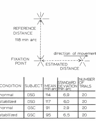
Through a comparison of acuity for stabilized retinal images with acuity for normal retinal images we have found that eye move -ments improve acuity very slightly at most, and that even this small improvement may be adequately accounted for by the residual fade -out effects commonly observed during prolonged viewing of stabilized images. Measurement of distance and angle estimation ability in both normal and stabilized vision reveals much the same result.
improve acuity only slightly (e. g. , by less than 0. 1 log unit in sine wave grating contrast sensitivity). Thus eye movements serve to
v
TAB LE OF CONTENTS
Chapter Title Page
-I INTRODUCTION
1
II EXPERIMENT AL APPARATUS
6
III CHARACTERISTICS OF EYE MOVEMENTS
29
IV ACUITY, A LINEAR ANALYSIS
70
v
THE ROLE OF EYE MOVEMENTS IN137
MONOCULAR ESTIMATES OF DISTANCE AND DIRECTION
VI SUMMARY AND CONCLUSIONS
165
APPENDICES:
I. Derivation of the Point Spread-Function 1 74 From the Line Spread-Function
CHAPTER I
"A rolling eye, a roving heart. "
Thomas Adams, Sermon, 1629 11She that has good eyes
Has good thighs. 11
John Suckling, The Goblins, 1638
No era has bred much agreement on the functions or corre-!ates of eye movements, and ours is no exception. This thesis concerns two alleged uses of eye movements, first, as an aid to acuity:
The limiting retinal factor in acuity seems to be the relation of receptor width to the highest optical gradient in a moving pattern [with move-ment produced by ocular rotation], rather than the average static illumination on one cone compared with its neighbors.
W. H. Marshall and S. A. Talbot, 1942 ( 1) Thus, there never has been any experimental basis for the 11dynamic1
' theories of visual acuity, according to which micronystagmus provides the basis for a mechanism which sharpens contrast and aids in acuity ...
G. Westheimer, 1965 (2)
The decrease in visual acuity with stabilized retinal images contributes [experimental] evi
-dence to a certain extent in favor of the dynamic theory of visual acuity.
M. Millodot, 1966 (3)
and, second, as an aid in estimating distance and direction: Every accurate comparison between two spatial dimensions,such as lines, angles or surfaces in the field of view, is made with the help of ocular move-ments.
2
The experiments reported above show that the perception of geometrical illusions does not depend on eye movements.
R. M. Pritchard, 1958 (5)
Far from being simply semantic differences, which in proper context would seem much more harmonious, these statements embody distinctly contradictory ideas concerning the role of eye movements in human vision. The conflicting theories are discussed in detail in
the following chapters. The experiments reported here attempt to
resolve the disputes by establishing either the existence or the
absence of physiological mechanisms which through the action of eye movements either improve acuity, or improve estimates of distance
or direction.
The following chapter gives the description of two rather
intricate pieces of apparatus which were employed in these
experi-ments, i.e. , the eye movement measuring system, and the retinal image stabilization apparatus. Chapter III deals with the behavior of eye movements during simple acuity and distance estimation tasks.
Chapters IV and V treat the problem from the complementary angle, that is, by measuring performance in these tasks both with and with-out retinal image motion. Thus Chapter IV treats changes in acuity due to cancellation of retinal image movement, and Chapter V treats distance estimation with and without retinal image motion.
One of the advantages of research on visual systems is the
wide range of available methods and theoretical frameworks.
Although the particular problem frequently suggests the method to
results, in particular, on the range of validity of the results. These factors necessitate fairly explicit definition of the type of experi-mental approach, as well as the theoretical framework within which the results are valid and, more importantly, useful.
The first step in this definition of method and theoretical framework is schematized in Fig. 1. This is done not so much to limit the appli.c_ation of my results, but rather to curb, or at least to circumscribe, the expectations of the reader. Fig. 1 should be interpreted to mean that the experiments discussed herein employ psychological or psychophysical methods in order to arrive, via an
>-i E-t H ...:i H (:Q < [.J..l > H E-t C.J H i:::i [.J..l ~ p.. [.J..l > H E-t ~ H ...:i < ~ O' Gestalt Psychology Behavioral Psychology, '\. sychology" Cybernetics
Studies Microelectrode
1 Marshall, W. H. & Talbot, S. A. 11Recent Evidence for Neural Mechanisms in Vision Leading to a General Theory of
Sensory Acuity Jt In H. Kl-liver (Ed. ) Biological Symposia
Vol. VII Visual Mechanisms, Lancaster: Cattell Press, p. 138 1942.
2 Westheimer, G. 11
Visual Acuity" Ann. Rev. Psychol. 16 , p. 368,
1965.
3 Millodot, M. 11
Foveal and Extra-Foveal Acuity with and without
Stabilized Retinal Images Jt Brit. J. Physiol. Optics 23,
p. 103, 1966.
4 von Helmholtz, H. Physiological Optics Vol. III (trans. by
J. P. Southall), Optical Society of America, Menasha,
Wisconsin, p. 168, 1925.
5 Pritchard, R. M. 11Studies of Visual Perception with a
Stabilized Retinal Image 11
Ph.D. thesis, Univ. of Reading,
6
CHAPTER II
EXPERIMENTAL APPARATUS
Introduction: The experiments to be described utilized two distinct systems: the first measures vertical and horizontal components of eye movements; the second stabilizes target images on the retina. Because the results described later in this thesis rely heavily on the accuracy of the devices, the construction and performance charac-teristics of these two systems are described in this chapter. Details concerning the design of these systems and their predecessors are treated elsewhere ( 1, 2, 3) and will not be discussed.
Both stabilization and movement measuring systems rely on a contact lens to follow the motions of the eyeball. For eye movement recording, a small lamp is attached to a rigid stalk protruding from the lens. As the eye moves, the lamp casts the shadow of a fixed edge back and forth over the face of a photomultiplier. The voltage output of the photomultiplier provides, in our apparatus, a linear measure of eye position over a 4° range.
passed through a telescope of magnification 1/2 and projected on the retina. Once this is done, eye movement through an angle a causes the target image to be translated through an angle a in the same direction, and the image is said to be "stabilized," since it does not move across the retina as the eye moves.
Contact Lenses
The crucial mediator of eye movements in both of the above
systems is the contact lens. Several different types are currently in use in other vision research laboratories. The two chief variants, as used by Ditchburn' s group ( 4) and by Yarbus ( 5), are shown in Fig. 1. The full scleral contact lens, illustrated on the left, differs only slightly from the type athletes wear (aside from the stalk) in that the
lens makes contact with the limbus, the junction of cornea and sclera,
and is more closely fitted to the sclera. In the athletes' type of full scleral lens, the plastic arches clear of the limbus since pressure on this area causes the subject pain. Those using the version illustrated put a local anaesthetic, for example, amethocaine, into the eye before wearing. Such discomfort is considerably greater with the Yarbus-type suction caps, as is the probability of corneal abrasions. For increased adhesion of the cap to the eye Yarbus serrates the edge of the cap. A detailed comparison of the two types of lenses is given by Barlow ( 6). He concludes that the full scleral lens may slip as much as
±
3. 5 min arc while the subject is looking ahead, whereas the suction type slips only ~ 40 sec arc under this condition. TheseFig
.
2-1
Methods
of
attachment
to
the
eyeball
.
Left
:
the
"full
scleral"
contact
lens
used
by
Ditchburn,
showing
an
attached
metal
rod
bearing
a
small
lamp
for
measurement
of
eye
movements.
Right:
the
"suction
cap"
developed
by
Yarbus,
showing
the
platform
for
support
of
stabilized
targets
.
necessary individual slippage measurements for each subject and each lens. In an effort to decrease the slip associated with scleral lenses, and at the same time to minimize the pain associated with
suction devices, the arrangement shown in Fig. 2 was developed, and used in all studies reported here. These are triple curvature contact lenses, with light weight tubes attached, through which suction may be applied.
Fitting and Construction: All subjects had full scleral molds taken of
their eyes by Mr. Robert Graham of Pasadena, a specialist in the fitting of contact lenses. Triple curvature plastic lenses were then made to his specifications, and checked by him for snugness of fit and optical correction. All subjects were corrected to 20/ 20. A light plastic stalk was cemented to the lens in a position where it would interfere least with the eyelids. Finally, a thin polyethylene tube (Intramedic ID. 015''x0 D. 04311
) filled with 2 percent sodium bicarbo-nate connected the space between lens and limbus to a water
manometer. By raising or lowering the manometer the lens was sucked onto the eye to any desired degree. With 23 cm of water negative pressure, subjects needed no anaesthetic and could remain with the lenses in their eyes for periods up to one hour without
ensuing discomfort or visual defects. No subject has yet experienced a corneal abrasion as a result of wearing these lenses.
POLYETHYLENE
TUBE
TO
MANOMETER
NASAL
TOP
VIEW
LAMP
POWER
LEADS
LEFT
LENS
FRONT
VIEW
Fig
.
2-2
Diagram
of
one
of
the
modified
full
scleral
contact
lenses,
showing
engraved
grid
for
slippag
e
measurement,
stalk
with
lamp
attached
(for
measurement
of
eye
movements),
and
polyethylene
tube
through
which
suction
could
be
applied.
the lens. Second is slippage of the lens over the eyeball. To rule out the first possibility, the lens was embedded in a block of paraffin from which stalk and lamp protruded. This block was clamped
under a microscope and weights of various sizes were suspended from the end of the lamp. Bending of the stalk was observed through the microscope, and amounted to . 0128 mm per gram weight at the tip. Using W
~stheimer
's ( 7) estimate of 27, 000 deg/ sec 2 as the maximum acceleration of the eye during a flick, and treating thestalk-lamp combination as a leaf spring with the above Hooke's
constant and with all its mass ( 0. 18 gm) concentrated at the tip, one finds that the stalk bends 4µ due to maximal flick acceleration,
giving an eye position measurement error of 0. 4 min arc. The tungsten lamp filament could not be observed to move even after the most intensive jarrings. The mirror could be attached to the stalk with equal tightness.
Lens Slippage Over the Eyeball: Of the several methods we used to quantify lens slippage, the most reliable and direct consisted of
observing through a microscope the movement of scleral blood
vessels relative to marks on the inside surface of the lens. For this purpose a grid of accurately spaced grooves was machined on the
inner surface of the lens, with 0. 0025" separating lines of the grid. The grid extended from the corneal portion to the temporal edge of
12
During all slippage experiments the subject's head was held by a bite bar, and his eye brightly illuminated by a microscope lamp. His instructions were either to fixate a small ( 4 min arc diameter) black point on white paper
6
feet in front of him, or to flick from one to another of two such points. Slippages were nearly identical for the two subjects under all conditions studied.Two fac_t~Hs, suction and direction of regard, greatly affected slippage. With no suction ( i. e. 0 cm vertical displacement between water level in the manometer and center of the lens) the lens remained immobile while the eye went through saccades and drifts of up to
30 min arc. Increasing suction decreased slip until a negative pres-sure of approximately 15 cm was reached. Further increase in suc-tion gave a slight addisuc-tional decrease in slippage. However, nearly all blinks displaced the lens a degree or more relative to the sclera, and the greater the applied suction, the more slowly the lens would creep back to its initial position. As a compromise between these effects of pressure we elected to work with 23 cm pressure. This allowed the lens to return after a blink in roughly 5 seconds.
conjunctiva behaves like a hemispherical rubber sheet, clamped at the outer edges to the skull, and attached around the limbus to the sclera. The lens behaves as though it were attached to the conjunc-tiva, about two mm from the edge of the cornea. This is the neigh-borhood of the scleral end of the lens' arch over the limbus. At
13 cm pressure, when the subject fixates first the central position and then a poii:it 4° nasal, the lens follows smoothly but only travels 3° 24'; and the conjunctiva 2 mm from the corneal edge goes through the same motion as the lens, though elsewhere the conjunctiva
slides both over the sclera and under the lens. If the eye continues in the same direction another 4°, the lens this time will only traverse
3°, and the slippages between lens, conjunctiva, and sclera will be more pronounced. Increased suction greatly flattens blood vessels of both conjunctiva and sclera, indicating that suction does not pull
one from the other, but rather presses the lens upon the sclera.
With 23 cm of water suction and eye straight ahead, how much
does the lens slip? When the subject fixated a point straight ahead and did not blink or flinch, we could see no slippage over 30 second intervals of time. That is, the error is less than 6 min arc in this interval. When the subject drifted slowly or made a saccade 4° in
14
perpendicular to the direction of movement.
The above discussion refers only to steady state errors, and tells nothing about the ability of the lens to track rapid eye move-ments. In fact, the observer can detect no transient slippage for either saccades or rapid drifts; however, the method is ill suited for the determination of rapid transients, since quite some time is
required for the observer to note relative positions of lens and blood vessels.
To answer the question of how much a lens slips due to its own inertia during a flick, we applied a similar force across the lens- scleral junction, but with the eye stationary, and measured the resultant slip. Specifically, we found that a 1 gram weight when hung on the end of the stalk (at 23 cm pressure) caused an 8 min arc displacement of the lens over the eyeball. When the weight was removed the lens returned to its normal position. The torque with respect to the center of the eye caused by this weight is 3430 gm cm 2 / sec2 (lgm weight at 3. 5 cm) and this torque when transmitted through the lens-sclera junction caused 8 min arc slip. During a flick the maximal torque transmitted through this same junction is equal to the product of the rotational inertia of the lens and the maximum flick acceleration. The maximum acceleration, as mentioned before, is 27000 degrees/ sec 2, or 4 70 radians/ sec 2. The moment of inertia of the lens about the rotational axis of the eye was estimated as
follows: lamp, wire, and cone joint weigh 85 mg and are 3. 5 cm from the center of the eye, giving a rotational inertia of 1. 0 gm cm 2;
gives 0. 6 gm cm 2 for its rotational inertia; the lens plus tear solu-tion has a weight of about 1. 1 gm, and, when approximated as a
segment of a thin spherical shell, has a rotational inertia of 1. 2 gm cm 2; therefore the sum of the rotational inertias involved is
2
2. 8 gm cm The manometer tube was neglected because it is taped to the subject's temple shortly after leaving the lens, thereby behav-ing more like a __ spring than a mass, and this action is included in the
measurement of static lens slip. The torque transmitted across
the lens-sclera junction during a flick is therefore 1360 gm cm2/sec2. Since this is four-tenths of the torque which causes 8 min arc slip,
and since slippage increased linearly with torque over the region we were able to measure, we expect transient slippage due to lens inertia during saccades not to exceed 3. 2 min arc. The large
acceleration during a flick is not sustained for more than a few milliseconds, and since the one gram weight was applied for more than a second in order to register 8 min arc slip, transient slippage due to lens inertia is probably less than 3. 2 min arc during a flick.
Eye Movement Recording
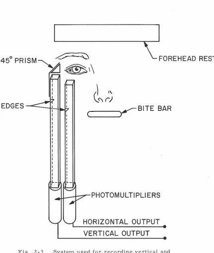
Subject Restraints: The recording apparatus combines techniques presented by Fender (8} and Byford (9). Two channels are shown schematically in Fig. 3; the assembly is duplicated under the
sub-ject's left eye (not shown} to provide simultaneous recording of horizontal and vertical components of movements of both eyes. The
subject's head is firmly held by both a dental cement bite bar
16
FOREHEAD REST
()
\\\..<'\
r)
~BITE
BAR
1--
I--, I
HORIZONTAL OUTPUT
VERTICAL OUTPUT
Fig. 2- 3 System used for recording vertical and
horizontal components of right eye movements. The lamp
attached to the subject's lens casts shadows of the edges
onto the photomultiplier faces. This causes the
[image:21.525.40.472.98.609.2]17
molars) and a forehead rest also molded to his head with dental cement. Both impressions are molded to solid aluminum stock, which, in turn, is bolted to the photomultiplier assembly. During all experiments the subject was seated comfortably in a medical examination chair with his head held rigidly vertical by the above supports.
Lamps: A variety of small medical lamps were used. Rimmer Bros. #cl 1 {unmounted} and Sylvania Mite-T-Lite, drawing respectively 200 and 20 milliamps, proved to be the most satisfactory in terms of weight and lifetime. The lamps were epoxied to a cone joint {for attachment to the stalk of the lens) and to black paper light shields, which prevented the lamps from shining directly into the subject's
eyes. Very fine wire {Belden 44 A WG) was soldered to the lamp leads and connected to a battery through a potentiometer. The wire leads
were taped to the subject's temple after allowing ample slack for eye movements.
18
photomultiplier, or by changing the level and gain of the DC
ampli-fiers which processed the photomultiplier output.
The rectangular tubes leading to the photocathode are
7xl 2xl 20 mm and lined with a non-reflecting black paper. The fixed
edge is 60 mm from the photocathode and 9 5 mm from the lamp. The
position of the fixed edge in the tube may be varied to increase either
the sensitivity _or the range of the measuring system. RCA
photo-multipliers (model 7767) are used in all channels; their high voltage
supply (usually 1200 v DC) is provided by two Kepko (model ABC
l 50M) power supplies which had 1. 0 mv rms maximum ripple plus
noise, 0. 05% variation with changes in load, and less than 0. 05%
drift in eight hours. Each high voltage supply feeds two photo
-multipliers in parallel. Immediately above each photocathode is a
rectangular mask fitted to eliminate non-linearities near the edge
of the tube.
Linearity of the Eye Recording System: To test for linearity of the
eye movement recording system a one inch diameter steel sphere
was built to function as a dummy eyeball. Two micrometers could
rotate the sphere about perpendicular axes. By means of a ten foot
optical lever the micrometers were calibrated to give angular
dis-placements accurate to 1 min arc over a 225 min arc range. One of
the small medical lamps was attached to a steel shaft protruding
from the sphere. The lamp was 3. 5 cm from the axis of rotation of
the sphere, just as it was on the lens stalk.
With the dummy eyeball clamped in position above the
19
the other micrometer vertical, the DC amplifier output voltage was
recorded for many different sphere positions. A plot of the results
is shown in Fig. 4. From this it may be seen that the output voltage
is close to linear over a 4° range in both vertical and horizontal
channels.
Frequency Response: By rotating a slotted disc between
photo-multiplier and lamp it was possible to measure the frequency
re-sponse of the entire eye movement recording system. The effective
input signal was a repetitive trapezoidal waveform whose duty cycle
depends on the width of the slots in the disc. For a 50% duty cycle
the response was of uniform amplitude as the disc rpm increased,
until the repetition rate of the trapezoid reached 330 cycles per
second. Response was 3 db down at 450 cps. Thereafter the falloff
was roughly 10 db/ decade. This low pass filter effect is entirely due
to the photomultiplier, whose high frequency gain increases with load.
Calibration of the Eye Movement Recording System: In order to
account for the brightness of the lights and the variable gains of the
high voltage power supply, the DC amplifiers, and whatever
appara-tus was used ultimately to record eye movements, it was found most
convenient to introduce a calibration step at the photomultipliers at
the start of each experiment. This was done by wiring a solenoid to
pull opaque vanes a short distance across the face of each
photo-cathode. At the end of a two second interval the solenoid was
de-energized and springs returned the vanes to their initial locations.
IOr
(/)
I
1-
c5
s
t
>
120
UP
/
60
0
60
MIN
ARC
~··
•
l20
DOWN
10
S
r
l20
NASAL
GO
0
MIN
ARC
/'
60
120
TEMPORAL
Fig
.
2-4
Photomultiplier
output
as
a
function
of
dummy
eyeball
rotation
along
vertical
and
horizontal
meridia,
illustrating
the
linearity
of
the
eye
movement
recording
apparatus.
the recording medium a two second wide rectangular pulse appeared
on each channel with small superimposed eye movements. The vanes
moved between rigidly fixed stops so that the calibration steps were
of uniform amplitude. Calibration of the calibration steps was done
by matching the rectangular pulse amplitude (caused by the vane) to
the amplitude caused by a known eye rotation. Here the dummy
eye-ball was again us ed.
Recording Media: The outputs of the DC amplifiers were recorded
on one or more of several machines, Most commonly used was a
Honeywell 1406 Visicorder, a 5 channel oscillograph with a frequency
range from 0 to 330 cps (flat within± 10% to 200 cps) and linearity
within 5% of full scale (8 inches), Where higher frequencies were of
interest, a Tektronix 564 storage oscilloscope with 3A6, 3A3, and
3B4 plug-ins plus polaroid camera was used, The oscilloscope was
either run directly from the DC amplifiers, or could be run from
analog tape playback. A CEC 7 channel AM-FM tape recorder
(model PR- 3300), operating at a tape speed of 1 7
I
8 ips (flat to300 cps), was commonly used to record experiments for later
analysis,
Digital Analysis: For digital analysis, each analog record must be
converted to digital form and transmitted to the computer. The
facilities available for this purpose were designed and constructed
at Caltech. Details of its workings have been described extensively
(for example, see reference 10), so only the meager outlines will be
22
plugboard-programmed, no-memory computer ("The Kludge")
which performs three functions: first, it can select data to be trans
-mitted (threshold circuits act to transmit only that data lying above,
below, or between certain levels - and/or the times at which the
signal crosses a given level); second, it can convert the selected data
to digital form at a rate of up to 10 kc; third, it can transmit the
digitized ( 12 bits plus sign) data through the IBM 7288 multiplexer to
a collection routine (BI0-40) time- shared on the IBM 7040. At the
input to the Kludge is a 6 channel multiplexer. Sampling of each
channel is also plugboard controlled, though the net rate can never
exceed 10 kc. Thus data is "preprocessed" by the Kludge, sent to
BI0-40, and, each time one of the BI0-40 buffers (in 7040 core) is
filled, the contents of the buffer are written on digital tape. Although
data selection and transmission rate are plugboard programmed into
the Kludge, either the Kludge or BI0-40 may be programmed to
determine the number of samples sent. BI0-40, furthermore, accepts
and writes on digital tape identifying characters to be associated
with the data. When the digital tape is written, "on line" processing
ceases. All further analysis is carried out via batch processed jobs
running under the IBJOB system; that is, Fortran IV or IBMAP
programs. These programs read the aforementioned digital tape by
interrogating a tape reading, unpacking (our 12 bit data 11
words11
are
packed in groups of three on tape) subroutine (KERFUS). Thereafter
processing conforms to standard batch processing techniques.
G. W. Beeler ( 11) was used in several experiments. This band-pass filters the eye position signal in the region ( 18 to 70 cps) of the spec-trum most characteristic of flicks. The filtered signal then enters a threshold detector (variable) which emits a pulse for all flicks larger than a predetermined magnitude. At maximum sensitivity the unit can detect flicks as small as 3 min arc, provided that a velocity of
roughly 3° /sec .or more is achieved in about 7 msec or less.
Optical System
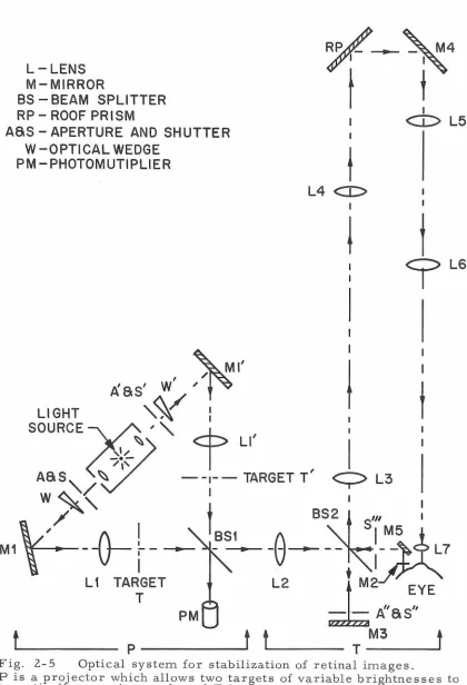
The optical system used for presentation and stabilization of visual stimuli is identical in all essentials to that described by
Clowes and Ditchburn ( 12). The apparatus for stimulation of the left eye is shown schematically in Fig. 5. This is duplicated for the right eye. Section "P" of the apparatus is a projector which allows either or both of two targets to be projected into the system, depending on whether shutters, S and S 1
, are open. The light source is a GE 18 amp
T 10 bulb with a horizontal ribbon filament. The luminances of either target can be controlled in two ways: first, by altering the positions of the optical wedges ( W and W 1
) ; and second, by partially closing
the 2 mm apertures, A and A1
, by means of solenoid-driven vanes
(not shown). In either case the net luminance seen by the subject can be monitored on photomultiplier PM (disregarding the constant trans-mission losses in the remainder of the system).
24
L-LENS
M-MIRROR
~~~4
t
i
I
BS - BEAM SPLITTER
RP - ROOF PRISM
ASS - APERTURE AND SHUTTER
W-OPTICAL WEDGE
<I>
L5
PM - PHOTOM UTI PLIER
t
I
'"Ml'
A'ss'
w
,'f~
LIGHT
'¥ :
L4
<D
i
SOURCE~
~, "
<f
LI'
~~~
...,,
I
t
er
t
ASS
~
- - 1 - -TARGETT'
Q
L3
W~<
I I/
t
BS~
t
s"'
tM1¥----o-~--- ~S-1--e----~:~7
L1
TA~GET
L2
t
M2
EYE
-~-
·
-
ff.'
as''
t
p _ _
___.t t.__ _ _
T - -
M3
-
--'-
f
Fig. 2-5 Optical system for stabilization of retinal images.
LG
P is a projector which allows two targets of variable brightnesses to be optically superimposed, and T is the telescopic system used for
[image:29.525.44.464.68.684.2]beam would be too large for the mirror to deflect. The targets must be placed one focal length from L2 since this results in a beam of parallel light rays incident on the contact lens mirror from any point of the target. If the targets were not a focal length away, movements of the lens mirror would change the magnification of the image, with consequent loss of stabilization.
The remainder of the system, T, collects the beam reflected off the lens mirror, and routes it, after the appropriate number of reflections and after magnification by 1/2, into the eye. For non -stabilized viewing, shutters occlude MS and expose a fixed mirror, M3, which, except for moving with the eye, performs the functions of the contact lens mirror. Lenses L3 and L4 act as a telescope of unit magnification to increase the field of the system. The roof prism, RP, and mirror M4 provide the requisite number of reflec-tions for stabilization; LS and L 7 act as a telescope of magnification 1/2. L6 is the field lens of the telescope, which not only greatly increases the field of view, but also may be translated along the axis of the telescope to provide fine control over the angular magnification. All lenses are achromatic doublets; Ll through LS are 6 cm in
diameter, and the telescope eyepiece is 1. S cm in diameter.
For experiments involving moving points of light as targets, Ml, Ll, and L2 were removed; a SO cm focal length lens was substi-tuted for L2; and a cathode ray tube face (Hewlett Packard l 22A
26
direct viewing is that the targets presented to each eye may be
independently controlled, but may appear fused into a single image.
Performance Data for Stabilization System: The telescopic system
described above images the light source aperture, A or A 1
, into the
plane of the eye pupil, a condition known as Maxwellian view. If the source were instead imaged on the retina, only a small region of the
retina would receive maximal light flux. Maxwellian view causes a
much larger area of the retina to receive the same maximal light
flux. Since the target is illuminated by parallel rays from the source, and the source is focused on the pupil, the target is optically at
infinity. The exit pupil of the apparatus is stationary with respect to
the apparatus, and is approximately 8 mm in diameter, thus the eye
pupil is well within the exit pupil for all eye movements considered
here.
One final important adjustment must be mentioned, that is,
the contact lens mirror must be perpendicular to the visual axis in
order for the retinal image to be stabilized. This may be easily
accomplished by bending the lens' stalk. Perpendicularity was
checked prior to each experiment by having the subject look at the
source of a simple star collimator; the beam reflected from his
mirror was made to coincide with the source point.
The degree of compensation provided by the optical system
for eye movements may be measured directly by substituting a
tele-scope with a graticule and a small eye mirror mounted on the front
for the eyeball, as described by Clowes ( 12). Movement of the
direct measure of the lack of compensation. For 2 0 telescope move
-ments the relative displacement between target and graticule was
3 min arc or less in the central 2° of the field and up to 4 min arc in
the periphery, neglecting the extreme edge of the field where com
-pensation was poor. Thus the retinal image in the central 2° is at
least 97. 5% compensated for eye movements, while within a 3°
28 Chapter II References
1. Byford, G. H. , Ph. D. thesis, University of Reading, 1960.
2. Ditchburn, R. W. & Ginsborg, B. L., "Involuntary Eye Move
-ments During Fixation", J . Physiol. 119, pp. 1-17, 1953.
3. Barlow, H. B. , 11
Eye Movements During Fixation11
, J. Physiol.
116, pp. 290-306, 1952.
4. Byford, G. H. , "The Fidelity of Contact Lens Eye Movement Recording", Optica Acta~' p. 223, 1962.
5. Yarbus, I. A. , 11A New Method of Studying the Activity of
Various Parts of the Retina11
, Biofizika ~' p. 165, 1957.
6. Barlow, H. B., "Slippage of Contact Lenses and other Artifacts in Relation to Fading and Regeneration of Supposedly Stable Retinal Images", Quart. J. Expt. Psychol.
_!2,
p. 36, 1963.7. Westheimer, G. , 11
Mechanism of Saccadic Eye Movements",
A. M. A. Arch. of Ophthalmology~' p. 710, 1954.
8. Fender, D. H., "Torsional Motions of the Eyebal111
, Brit. J.
Ophthal. ~' p. 65, 1955.
9. Byford, G. H. & Stuart, H. F. , "An Apparatus for the Measure
-ment of Small Eye Move-ments11
, J . Physiol. 159, 2 pp., 1961.
10. McCann, G. D. & Fender, D. H. , 11
Computer Data Processing and Systems Analysis Applied to Research on Visual Percep-tion" in Neural Theory and Modeling, ed. Richard F. Reiss, pp. 306- 324, Stanford University Press, 1964.
11. Beeler, G. W. , 11S tochastic Processes in the Human Eye
Control System 11
, Ph. D. thesis, California Institute of Technology, 19 65.
12. Clowes, M. B & Ditchburn, R. W., 11
An Improved Apparatus for Producing a Stabilized Retinal Image 11
29
CHAPTER III
CHARACTERISTICS OF EYE MOVEMENTS
Introduction: Certain characteristics of eye movements have been
dealt with extensively in the literature, particularly those regarding
the action of the eye as a "position servo" and as a tracking
mechan-ism. Less emphasis has been placed upon the relevance of eye
move-ments to the visual input. This chapter attempts to forge just such a
link, by relating the characteristics of eye movements to the type of
visual information absorbed during execution of the eye movements.
Before presentation of the experimental data, the basic
capa-bilities and limitations of the extraocular muscles are set forth in
terms of their anatomy, physiology, and innervation. These are then
related to the three categories of eye movement: flick, drift, and
tremor. The manner in which these components of eye movements
are arrayed in different visual tasks, and the degree of control
exercised over them, constitute the subject matter of the experiments.
Anatomy and Innervation of the Extraocular Muscles
General Characteristics: Six extraocular muscles are found in all
vertebrate classes, as well as in man. These are the four rectus
muscles, usually termed superior, inferior, medial and lateral, and
the two obliques, inferior and superior. In man all except the
30
structure surrounding the optic nerve. The inferior oblique
origi-nates in a depression on the superior maxilla, on the nasal wall of
the orbit. Extraocular muscle development and anatomy are
elegantly described by Gilbert ( 1 ). Ewald Hering ( 2) in 18 79 illus
-trated the rather complex effect that contraction of any one muscle
has on rotation of the eyeball. Only the horizontal recti directly
oppose each other throughout their range of contraction; thus none of
the other four muscles has a single antagonist, but two or more must
work together to balance the contraction of any one of the four. The
superior oblique is innervated by the trochlear nerve (IV); the lateral
rectus by the abducens (VI); and the remaining four muscles by the
oculomotor nerve (III).
Neural Pathways to the Eye Muscles: The nuclei of the three cranial
nerves mentioned above all lie in the brainstem, i. e. , relatively far
from the primary visual pathways. Walls ( 3) attributes this to the
propinquity of vestibular and oculomotor nuclei, saying that the
original function of eye movements in the evolutionary scheme was to
provide a stable platform for the retina, where "stable" was defined
by the vestibular apparatus, not the visual input. The oculomotor
nucleus lies ventral to the aqueduct of Sylvius, near the midline.
th
The IV nucleus lies close by, but somewhat laterally and ventrally.
th
The VI nucleus lies in the tegmental portion of the pons. It has
been suggested that Perlia' s nucleus, on the midline between the
oculomotor nuclei, functions in convergence; although more recent
experiments on macaque and man do not bear this out (c. £. Warwick4).
31
cats has not clarified the organization of this nucleus. All
investiga-tors believe the IIIrd nerve to be homolateral in function, as is the
abducens, but the trochlear is not; and the majority (Danis (5) and
Szentagothai ( 6) ) think that the anterior section of the oculomotor
nucleus controls the muscles with insertions on the upper part of the
orb, while the posterior section controls those with insertions on the
lower part of the orb - nerves to the medial rectus lying in between.
A few pathways to these nuclei have been worked out. The
parabducens nucleus sends processes through the nearby abducens,
and via the medial longitudinal fasciculus to the medial rectus
sec-tion of the contralateral oculomotor nucleus. This pathway insures
the coordinated function of the horizontal agonist-antagonist muscle
pair, even though the cell bodies of their respective nerves lie in
different nuclei on either side of the midline.
The lateral vestibular nuclei have been shown to connect to
IIIrd, IVth, and VIth nuclei by Crosby (7). Electrical stimulation of
almost any part of the brainstem produces deflections of the eye; and,
according to Wagman et. al. (8), stimulation almost anywhere on the
cortex or subcortex of the macaque produces either version or
centering of the eyes. As CNS electrical stimulation is susceptible
to many interpretations no review will be given here. The interested
reader is referred to the work of Bender (9) for a review of this
voluminous literature.
Cellular Aspects of the Extraocular Muscles: Cooper and Daniel ( 10)
have found up to 50 muscle spindles per human extraocular muscle,
32
well. In this and other cellular aspects the six muscles are
appar-ently similar. It is still not known whether muscle fibers extend the
entire length of the muscle. Multiterminal innervation of single fibers is well established but polyneuronal innervation has only been
demonstrated in cat eye muscles ( 11).
The ratio of muscle fibers to motor nerve fibers is about 3: 1 for human ext:r:i.nsic eye muscles, making these the most richly
innervated muscles of the body. The exact ratio is difficult to specify
since some of the nerve fibers are sensory. Donaldson ( 12) has
analyzed the axon diameters of the occulomotor nerve of the goat and
found that 30% of the axons are about 5µ in diameter, while the others
are in the neighborhood of 15µ across. He postulates that many of the smaller fibers serve a gamma efferent function, controlling
stretch of muscle spindles. Bach y Rita ( 13) has evidence (vide infra) that the small nerve fibers in the cat are motor axons to small
muscle fibers, but not gamma efferents.
There is a spectrum of muscle fiber sizes in human
extra-ocular muscles, ranging in diameter from 9 to 40µ. The same fiber
spectrum occurs in the cat, and here the morphological and
physio-logical properties of the large and small fibers have been carefully
investigated ( 13, 14). The fine, "slow" extrafusal fibers have multiple en grappe nerve endings, poorly defined fibrils
(Felderstruktur), low ( 3 per second) spontaneous end plate potential
(EPP) rates, a low ( 25 cps) fusion frequency, and finally a long
Bach y Rita ( 13) claims they do, although he ''often'' encountered slow fibers which did not. Hess (14) on the other hand, claims that, in the normal state, only slow graded potentials are seen in these fibers, with graded contraction determined by the degree of
depolarization.
The large "fast" fibers have quite different characteristics: single en plaque motor nerve endings, well defined fibrils
(Fibrillenstruktur), high ( 19 per second) spontaneous EPP rates, an extremely high fusion frequency ( 500 cps), negligible latency, and a rise time of 5 to 7 msec with a half decay-of-contraction time of 8 msec. Figures relating to contraction refer to a muscle loaded by
2 to 6 g, and stimuli sufficient to produce 2 to 3 g twitch tension ( 13). Two-thirds of the muscle fibers in cat are of the fast type, and these are usually more numerous close to the center of the muscle. Selective contracture of the slow fibers with succinylcholine produces a tension of one-third the maximal tetanic tension. These character-istics have led to the hypothesis that slow fibers are responsible for the slow, "tonic" movements of the eye, while both types contribute to rapid vergence motions.
34
discharging and threshold receptors occur, in parallel and in series
with the contractile elements, sensing both length and rate of stretch.
Despite this panoply of sensory nerves, no stretch reflexes have been
found in the extraocular muscles, indicating a unique relationship
between the brainstem and this set of muscles since almost all other
muscles with direct CNS innervation have stretch reflexes.
Even more surprising is the fact, known since the days of Helmholtz, that we have no independent ''position sense 11 to tell us
which way our visual axis is pointing. An occluded, lightly
anaes-thetized (cocaine in the conjunctival sac) eye may be rotated by the
experimenter without the subject being aware of any movement, and
without causing perceptible reflex movement in the other fixating,
unoccluded eye ( 1 7). The same results hold if both eyes are occluded
and rotated. Similarly if the subject is asked to rotate his occluded
eyes, he cannot tell whether they have been held stationary or not,
and if they are held but not occluded he interprets his visual world as
if he had moved his eyes, i. e. , his visual world seems to rotate. The local anaesthesia applied during these experiments does not
impair the subject's normal eye movements. Thus any stretch or
position information derived from the receptors in the muscles does
not reach the conscious levels, and is not even used at the lower
levels to correct visual information or to cause reflex movement. Just what it is used for remains one of the deeper mysteries of the
field. The experimental data, then, point to the fact that all
informa-tion about eye position is derived from commands, "efference copy, 11
from proprioceptive feedback from the muscles themselves.
Eye Movements - Background
Movements of the eye are conveniently broken down into three
categories: flick, tremor, and drift. The fundamental reason for
this categorization is the differing appearances of the three modes of
movement in a. plot of eye position versus time.
Tremor: Continuous small oscillations of the eye, with amplitude
between 5 and 15 sec arc ( 18), and frequency in the range 30 to 80
cps, are called tremor. Since the inter-receptor spacing in the fovea
is 2- 2.
6µ
(Polyak, 19)), and the distance from the rear nodal point ofthe eye to the retina is 1 7 mm, the angular separation of the foveal
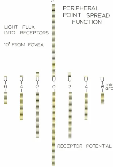
cones is 24 to 30 sec arc. Ten degrees from the fovea the
inter-receptor spacing is 2 min arc. Thus tremor moves the foveal image
at most one inter-receptor space at 30 to 80 cps, but not nearly this
amplitude in the periphery. The cause of eye tremor is thought to be
unfused contractions of fast muscle fibers corresponding to the
main-tained nerve discharge to these muscles. Although the direct
con-firmation of this has not been carried out with humans, the data on
cat eye muscle properties ( 20) is consistent with this assumption.
Flicks: These are the very rapid movements of the eye. Some are
under voluntary control and called for this reason "saccades 11 , but
the smaller "fixational 11 flicks with amplitudes less than about 10
min arc are made without the knowledge, and even against the will of
36
have a characteristic direction and amplitude for any particular
sub-ject but their time course is similar to that for saccades. The peak
velocity of either form of flick is roughly proportional to the log of
the amplitude ( 21), and the duration is proportional directly to the
amplitude ( 20). Typical magnitudes are 40 msec duration and 350
degrees/ sec peak velocity for a 10° saccade.
Evidence for the manner in which eye muscles operate during
a flick comes from two chief sources: electromyography of the
extra-ocular muscles in humans, and studies of isometric and isotonic
flicks in man and in excised cat lateral recti. Needle electrodes in
as many as four eye muscles, providing simultaneous records of the
electrical activity in two agonist-antagonist pairs, give the following
information ( 22): during a 20° saccade there is a high, maintained
discharge in the agonist, inhibition of the antagonist, and
co-contraction of the muscle pairs not involved in moving the eye.
Tamler ( 22) concludes that the agonist pulls continuously and with a
constant firing rate of the motor units throughout the saccade,
where-as activity in the antagonist is totally inhibited, obviating the
pos-sibility of active checking by the antagonist at the end of a flick.
Movement artifacts, however, make these claims somewhat difficult
to fully substantiate.
Direct electrical stimulation of partially excised cat lateral
recti by Robinson ( 20) indicates that there is very little variation in
tension rise time with an increase of the stimulus rate above 100 cps
or with an increase of muscle length. Since he stimulated both large
population is somewhat vague. With no stimulation Robinson found
that the passive tension developed in the muscle is proportional to
its change in length ( 2 g per degree). In humans he found that attempts at saccades with a restrained, occluded eye resulted in
50 msec of rapidly increasing tension followed by a slow, 350 msec, decay to a steady level which is 2/ 3 of the peak tension. This
lingering high .tension, if it is not caused by proprioceptive feedback,
which is unlikely in light of the earlier discussion, contradicts the
work of Tamler et. al. (22) who describe no large, continued muscle potentials following the saccade. More recent work by Bach y Rita
and Jampolsky (private communication, 1967) indicates that there
may be a small maintained discharge following the saccade, although
there still appears to be a dichotomy between the large post-saccade
tension measured by Robinson and the small post-saccade muscle
potentials measured by Jampolsky.
Two classes of drugs have large effects on the extraocular
muscles and their innervation. Succinylcholine causes contraction of
slow fibers in the extraocular muscles, with no commensurate
shortening of the fast fibers ( 13). Barbiturates in even moderate doses cause the rate of flicking to increase threefold or more ( 23).
The action of succinylcholine is due to its ability to mimic the end
plate transmitter, acetylcholine, and depolarize the muscle fiber.
Sensitivity to these molecules is apparently localized under the
end-plates in large, fast muscle fibers, but spread out along with the
en grappe nerve endings over the surface of the slow muscle fibers.
38
of slow fibers to succinylcholine. The mechanism by which
barbi-turates increase the flick rate is not understood.
Drifts: As the name implies, drifts are slow movements of the eye,
usually with a velocity less than 10 min arc per second. When made
voluntarily, as during a tracking task, they are called smooth
following movements to distinguish them from the saccadic jerks.
Bach y Rita and Ito ( 13) think it likely that drifts are caused by the
slow occulomotor system, i.e. , by the smaller motor axons
innerva-ting small and slowly conducinnerva-ting muscle fibers. Drift during fixation
has been extensively studied ( 24, 25). Because its amplitude and
direction are little affected by visual factors the authors concur that
drift is primarily a manifestation of some instability of the
occulo-motor system. Large drifts during slow tracking tasks, on the other
hand, are not instabilities at all, but true tracking movements.
Rashbass ( 23) has offered evidence that these smooth following
ments reflect a velocity tracking system, whereas the saccadic
move-ments reflect an independent position tracking system.
In closing this summary of the components of eye movement,
we should note that movements of large amplitude and intermediate in
velocity between flicks and drifts are occasionally seen, though no
subjects appear to use such movements in any consistent manner.
Eye Movement Experiments
Introduction: The object of this series of experiments was to discover
39
preceding section, are arranged in a pattern characteristic of the
visual task being performed. Data from previous investigations,
which are described fully in Chapters IV and V,have linked eye
move-ments with two particular types of visual tasks: those involving
acuity targets, and those calling for visual estimates of length or
orientation. However, evidence for these links is rather indirect. In
particular, no· one has demonstrated a unique relationship between
the pattern of eye movements and either of these visual tasks. The
experiments reported below seek to elucidate the extent, and perhaps
the mechanism, of the coupling between visual information inflow
and eye movements by analysis of eye movement patterns generated
during two such visual tasks.
Since eye movements are quite erratic and susceptible of
many interpretations when an extended pattern is presented, we
decided to use the simplest possible optical inputs, namely one or
two point light sources, in the two visual tasks. In order to separate
patterns of eye movement specific to the target from eye movement
patterns specific to the task, two control experiments were carried
out. The first involved no change of target geometry, but the task
was changed from one of the acuity type to one involving no acuity
discriminations. A comparison of the results of these two
experi-ments gives the eye movement patterns associated exclusively with
acuity discriminations.
In a similar fashion eye movements were measured during a
task which involved estimates of distance and direction. As a control,
40
required no estimate of distance or direction. A comparison of
these results shows patterns of eye movement unique to the distance
and direction estimation task.
Eye Movements During A Simple Acuity Task: During an earlier
investigation we found that the ostensibly simple command to fixate
a point light source could be interpreted in two quite distinct ways
by the subject, and that the resulting eye movements were noticeably
dis similar. Fixation according to one interpretation means that the
eyes should be held as motionless as possible; according to the other
interpretation, fixation means that the spot should be seen clearly and
distinctly for the duration of the experiment. Subjects were
instructed to perform each of these tasks, described to them in the
above terms. To put the same distinction in a more physiological
context, motionless fixation involves conscious minimization of motor
outflow, whereas what we will call sentient fixation requires the
conscious maximization of sensory visual inflow. The fact that the
target remains the same, and only the subject's criteria change,
provides a direct method for identifying those parameters of eye
movements which are specific to a simple acuity task.
Fig. 3-1 and 3-2 show the eye position vs. time data under the
two fixation conditions as recorded on the Visicorder. The records
were obtained from a single subject (DSG) during one experimental
session. Several factors are· immediately obvious from these
records: first, that left and right eyes behave virtually identically
I
RIGHT
OR
UP
BLINK_.
RV
I
30
min
arc
I
sec
I~
•I
Fig. 3-2 Eye movements during s e ntient fi x ation of s ub j ec t D SG , obtained in the same session as those of the previous figure. Gai n of t he r i g ht ve r ti c al c h a nn el is a g ain lower than that of the others .amplitude are increased during sentient fixation; third, flick
direc-tion is more random during sentient fixadirec-tion.
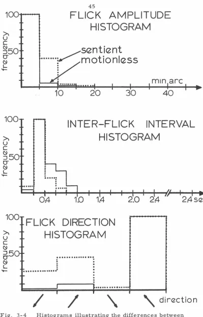
The above observations are confirmed by the histograms of
Fig. 3-3 and 3-4. For both subjects flick amplitudes become larger
and interflick intervals become shorter during sentient fixation.
Finally, both subjects when trying to hold their eyes motionless have
a definite preferred flick direction, but during sentient fixation their
flick direction becomes more random.
These histograms were acquired from records of the left eye,
monocular fixation {right eye covered by a patch) in a dark room with
the subject viewing a stationary bright point {diameter 4 min arc) on
the oscilloscope through the telescopic system previously described.
Records of binocular fixation revealed no notable differences between
monocular and binocular conditions. Preferred flick direction is the
same for both eyes and is identical to that in monocular viewing;
occasional rapid drift vergence motions {about 8 min arc nasal
movement simultaneously in each eye, corrected in about 1 second)
were seen during sentient fixation, but the vast majority of flicks and
drifts were conjugate, i.e. , in the same direction, of nearly the same
amplitude, and synchronous in the two eyes. Table 3-1 gives the
characteristics of the records from which the histograms were made.
The two subjects have substantially different mean flick rates;
how-ever, both increase significantly during sentient fixation.
By playing the tape recorded horizontal and vertical measures
of eye position into the corresponding channels of an oscilloscope, and
100
>-u
z
~o
...
0
w
0::
LL
I 00
+--'PP.PP.!!I.
>-
:
u
:
z
:
w
... :
::>50
0
w
0::LL
0
.4
...
,
•
.
•.
.
•
• •44
FLICK AMPLITUDE
HISTOGRAM
... VSENTIENT
:
MOTIONLESS
1
0
.
.
.
20
...
IN ARC
30
4
0
INTER-FLICK INTERVAL
.
•
.
•
•
•...
•.
• •...
HISTOGRAM
•...
...
.
.
.
.
... .
1.0
1
.4
1
00
...---...
>-FLICK DIRECTION
HISTOGRAM
u
z
w
650
w
0::LL
/
•••••••••••••••••••
•
•:
... .
.
:.
---~···
.
/
\ direction
Fig. 3-3 Histograms illustrating the differences between
100...-~
FLICK AMPLITUDE
HISTOGRAM
sentient
[image:50.526.64.463.45.667.2]····ymotionless
...
10
20
30
min arc
40
100
~
u
c
INTER-FLICK INTERVAL
HISTOGRAM
~50
CJ~
L.
-
...
.
OA-
1.4
10
°
FLICK DIRECTION
~
-u
c
~
--6-50 ...
~
....
L.HISTOGRAM
.
... .
.
.
.
.
.
:
.
.
...
.
.
. . .
.
. .
..
..
.
.
.
.
.
.
....
.
-
..
.
.
.
2.0
I ~-·
... .
/
I/
'
24
I
I
2A-sec
I •
' \
direction
Fig. 3-4 Histograms illustrating the differences between