Three Phase Induction Motor Protection System
Avadhoot. S. Thube1, Pritam. B. Chavan 2, Tatyasaheb. Y. Khamgal3, Kedarnath. G. Khaire 4, Deepika B. Srivastava5
1, 2, 3, 4, 5
Department of Electrical Engineering, Bhivarabai Sawant Institute of Technology and Research, Wagholi, Pune.
Abstract: Induction motors are utilized as a part of numerous modern applications in an extensive variety of working ranges in view of their basic and strong structure, and low manufacturing costs. Giving an insurance framework is imperative in enterprises. The reason for improvement of this project is to provide safety to industrial motors, lift motors, pumps and so on. The principle motivation behind our project is to protect an induction motors from faults, for example, single phasing, overvoltage, over temperature and under voltage. In this project we are utilizing a three stage supply by using three single phase transformers. On the off chance that any of the stages, out of the 3 stages is missing or if temperature of the motor during operation exceeds threshold value or if the voltage exceeds/drops threshold value motor stops immediately.
The main relay which is powered through a set of four relays gets disconnected because of one relay not being powered. Furthermore, we are utilizing a microcontroller for identification of these detection and a LCD show to indicate which type of fault is occurred. This paper has a tendency to develop for protection of three phase induction motor from single phasing, phase reversal, overvoltage and under voltage.
Keywords: Induction Motor, Fault Protection, Simulation, Over Voltage, Under Voltage, Phasing Out, Over Current, Microcontroller
I. INTRODUCTION
There are an extensive variety of ac motor and motor characteristics in existence, as a result of the numerous duties for which they are utilized. All motor require protection, but luckily the more fundamental issues influencing the decision of protection are free of the kind of motor and the over load to which it is connected. Induction motor when supply with higher voltage than evaluated then induction motor over heated. In our project a variable resistance is utilized when supply voltage is lower than rated then voltage drop over the resistance is higher than it protect the motor from this fault. At the point when supply voltage is lower than voltage drop over the resistance is lower than specified value and motor fails to start. At the point when supply is just a single phasing, this is single phasing issue and supply voltages rated and at the end of the day motor fails to start. In case of motor overheating lm sensor is utilized which sense the temperature of winding in the exceed the specified the limit then once again the motor fails to start. It is highly desired that three phase induction motor works freely from all type of fault. Induction motor is most widely utilized motor. It requires less maintenance as compared to other electrical motors. The primary goal of the work is to make a cheap and reliable protection system for three phase induction motor system. The protection system should protect the from voltage unbalancing, single phasing, under voltage, over voltage and thermal protection. Further to enhance system to run the motor under single phasing. Classical monitoring for enlistment motor are for the most part given by some combination of mechanical in electrical monitoring equipment. Mechanical types of motor detecting are also limited and ability to identify electrical fault, for example stator protection failure. Furthermore, the mechanical parts of the gear can cause issues throughout operation and can decrease the life and the efficiency of the system.
We describe the system for monitoring and controlling of induction motor. A low cost of the system proposed to monitor the parameters of the induction motor, for example, voltage, current, temperature of the winding, speed of the motor and power factor. Continuous monitoring is done for every one of these elements and warning the message is sent to in charge person if there should be set limited value this provision in proposed system facilitated the action to be taken before actual fault occurs on motor. What's more, henceforth enhancing the execution of the motor by maintaining a strategic distance from its tripping took after by fault. What's more with the monitoring, the speed control of the motor is performed. On the off chance that an over-load occurs i.e. Current exceed the maximum limit the relay circuit will turn on the buzzer.
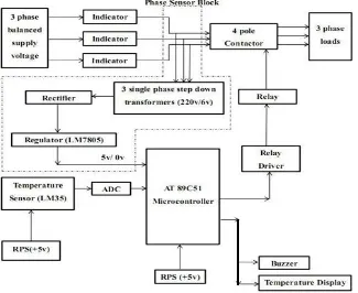
II. BLOCKDIAGRAMOFPROPOSEDSYSTEM
of fault we used a LCD Display. Relay unit is connected to the motor through contactor. And all protection blocks are shown in diagram.
Fig.1: Block Diagram Of Proposed System
A. Over Voltage Protection
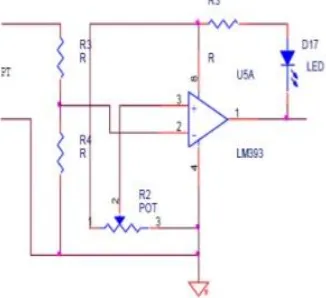
Over voltage protection system of 3 phase induction motor, protects the motor from over voltage, the voltage which is higher than the appraised voltage. In circuit diagram of overvoltage protection it comprises the comparator which think about two voltages one is supply and another is drop over the variable resistance. At the point when the voltage drop over the variable résistance is higher than specified value then comparator creates signals. This signal is sustained to microcontroller and microcontroller makes the proper move as appeared in fig 2.
[image:3.612.200.410.510.705.2]B. Under Voltage Protection
Under voltage protection of 3 phase induction motor provides the protection from the under voltage. When supply system has low voltage than the rated of induction motor then under voltage protection section of protection supply is provided to motor. Single phasing works. It has same concept as overvoltage it also has comparator which compare two voltage one form supply and another from the voltage drop across the variable résistance. When voltage drop across the variable resistance is lower than specified value, this signal sends to microcontroller and microcontroller stop the operation of motor in the case of running and fails to operate in case of starting. This circuit works in same manner as overvoltage protection works only the different is that value set by preset. In this case set value is minimum but in overvoltage case set values by preset resister. When appropriate voltage drop across the resister exceeds from the set values of preset the signal sends to microcontrollers.
C. Single Phasing
[image:4.612.233.396.354.503.2]In single phasing protection to 3 phase induction motor, if other two phases is faulted and only one protection of motor section starts functioning. Generally in single phase supply voltage is lower value than specified value. On this value of voltage motor is unable to start. Comparator which compares single phasing supply voltage and rated specified voltage, and single sends to microcontroller and microcontroller generates single which stop the motor if motor is running and does not allow to motor start in case of standstill. Sometimes single phasing protection looking much motor important when the motor is tight which important function like furnishing, pump driving and crane driving etc. This fig. Show the typical single phasing condition in three phase induction motor where one phase break down and motor is only supplied by remaining phases which is equivalent to single phasing condition. Single phasing occurs as a result of several possibilities. A loose wire, a bad connection, bad starter contacts, overload relay problems, a bad breaker, a blown fuse, and other things can cause this destructive condition. Obvious signs are a louder than normal humming from the motor and/or a shaft that vibrates rather than rotating.
Fig 3. Diagram of single phasing
D. Phase Reversal
Phase reversal problem occurs in motor when the supply phase is reversed due to wrong connection (except than ryb) due to phase reversal motor starts running in anticlockwise (opposite direction from normal) would cause operation and safety problem. Most of three phases motor run opposite phases. This type of protection is used in application like elevators where it would be damaging or dangerous for the motor to run in reverse. Generally when motor is connected with the important application then type of protection being much more important .when the load is connected with motor then reversal of phase means direction of rotation is changed. It could cause serious problem therefore much more care is required to protect the motor form such type of fault. The overheating protection system is placed to turn the motor off when the exceeds heat is generated within the motor. This protection system rested the motor cools to safe operating temperature. Direction by switching the connection of any two of three although the motor having shut down because it tripped the thermal limit in inconvenient.
E. Overheating Protection
purpose. This sensor is connected to comparator inputs. With the help of sensor which sense the temperature of winding & its temperature exceeds to some particular level then comparator sends this signal to microcontroller as shown in fig.4.
Fig 4. Diagram of overheating protection
III. SIMULATION& RESULT
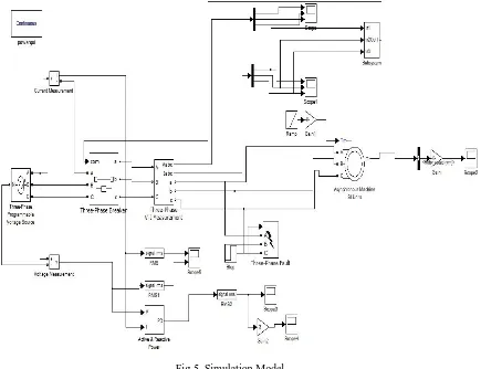
A three phase induction motor external faults simulation is prepared in Matlab /Simulink environment with varying operating voltages and load. OL, OV, UV, SP (for each phase), VUB and normal conditions are simulated to obtain three phase RMS line voltages and RMS line current values. The fault simulation is prepared using 3 phase, 50Hz, 4 kW/5.4 HP, 400 V, 1430 rpm, star connected induction motor. Induction motor block in Matlab/Simulink is based on arbitrary reference frame theory and contains highly nonlinear modelling equations.
Fig 5. Simulation Model
A. Simulation Results
[image:5.612.98.533.346.680.2]-50 0 50 100
Fig:- Phasing out of three phase induction motor. -15
-10 -5 0 5x 10
4
0 0.05 0.1 0.1 5 0 .2 0.25 0.3 0 .35
-5 0 5 10 15x 10
4
Fig.6: Relay Operation During Phasing Out Fault
The operating voltages more than 10% rated operating voltages are considered as overvoltage condition in simulation. Fig.7 shows the three phase voltages and currents and Fig. shows three phase RMS voltages and currents for OV condition. 110.8% OV of rated voltage initiated at 1.12s
0 0.05 0.1 0.15 0.2 0.25 0.3 0.35
0 1000 2000 3000 4000 5000 6000 7000
Fig:- Over voltage of three phase induction motor.
Fig.7: Relay Operation During Over Voltage Fault
The operating Current more than 10% rated operating current are considered as overcurrent condition in simulation at 1.12s
0 0.05 0.1 0.15 0.2 0.25 0.3 0.35
0 0.5 1 1.5 2 2.5x 10
4
Fig:-Over current of three phase induction motor.
Fig.8 Relay Operation During Over Current Fault
The operating voltages less than 10% rated operating voltages are considered under voltage condition in simulation. Fig.9 shows the three phase voltages and currents & three phase RMS voltages and currents for UV condition. 87% UV of rated voltage initiated at 1.14s. 0 10 20 30 40 50
0 0.05 0.1 0.15 0.2 0.25 0.3 0.35
0 50 100 150 200 250
Fig:-Under voltage of three phase induction motor.
Fig.9 Relay Operation During Under Voltage Fault
considered in the case. Fig 10 shows the three phase voltages and currents and three phase RMS voltages and currents for VUB condition. Two phase under voltage VUB initiated at 1.13s.
-1000 -500 0 500 1000 -500 0 500
0 0.05 0.1 0.15 0.2 0.25 0.3 0.35
-500 0 500
Fig.10: Protection From Unbalance Supply
IV.HARDWAREDESCRIPTION
A. Microcontroller & Power Supply
The microcontroller IC which we utilized is Atmega-16. It is a 40 pin IC. The microcontroller receives signal from different monitoring units of the induction motor. Assurance should be possible all the more successfully and with this microcontroller. Simple information sources are changed over into advanced flags by ADC inside the microcontroller. The information gathered from the motor are displayed in liquid crystal display (LCD).
B. LM35 Temperature Sensor
The temperature of the engine winding is measured utilizing the lm35 temperature sensor. The lm35 series are type of precision integrated circuit temperature sensors. The output of this sensor is linearly proportional the Celsius. For each 10 mv, the temperature value will be increase in 1 degree.it can measure the temperature from - 55° to +150°c range. The measured temperature from the sensor unit was displayed in LCD and stored in pc through the controller circuit.
C. Comparator Circuit
It is one of the important part of the system circuit used in the project that compares rated value of the voltage, current and temperature faulty value and accordingly generates the signal to operate the relays which disconnect the motor from supply. In comparator circuit we have used two IC and two relays. One of the IC is used for faulty current detection to give signal and other is used for protecting the motor under/over voltage , temperature rise condition and sent signal to relay 2 to operate. The output of
comparator circuit is given DOL starter of the induction motor for switching the motor.
D. Relay
A relay is an electrically functioned switch, the flow of current through the relay’s coil creates a magnetic field which attracts a switch and alters the switch contacts. Relays let one circuit to button a second circuit which can be totally divided from the first. There is no electrical connection in the relay between the two circuits; the connection is magnetic & mechanical. To make relay through microcontroller, a ULN2003 relay driver IC is used.
V. EXPERIMENTALSETUP
Fig.11 Experimental Setup
VI.RESULT
In the proposed framework variable resistance (pre-set) is utilized for modifying reference voltages for various parameters, for example, under/over voltage, over current, over temperature, over speed, frequency and phase failure. The qualities are set for the maximum ratings 430 V, 7.1 Amp & temperature up to 50º C. If the value of any parameter goes beyond the reference value than the relay unit releases the contact of the motor from the circuit. Consequently the motor naturally turned–off. This is the means by which the induction motor can be protecting effectively from the fault utilizing this microcontroller based protection system. This system can be tried with different rated induction motors.as per the planned esteem, designed value, the system withstand current up to 10 Amp, voltage up to 450V, temperature up to 50 ºc
VII. CONCLUSIONS
The induction motor have now become very popular as compared to other motor for many of the industries because it is low cost simple and extremely rugged construction, high reliability high efficiency and good power factor, low maintenance cost. Induction motors are utilized as a part of different industry, for example, paper process, sugar industry, for driving the mechanical frameworks. The maintenance of an induction motor is very essential. The observing of induction motor through wired correspondence is costly as well as the information correspondence may influence because of physical conditions like human hazards. Hence wireless communication becomes price worthy turns on excellent substitute for observing as well as the control of induction motor. It upgrades the execution of the motor.
For smooth running of motor by and large fixation on supply voltage under as far as possible and load which is driven by the motor to likewise be under as far as possible.
REFERENCES
[1]. Vikram Singh, Abhishek Gupta, Ankit Gupta, Aniruddha Garg, Ankush Khandelwal, Akshay Gupta “Induction Motor Protection System”, Imperial Journal Of Interdisciplinary Research (IJIR) Vol-3, Issue-3, 2017
[2]. Devesh Kumar, Piyush Kumar Verma, Brijesh Kumar Singh, Ravindra Singh, Vishal Singh “Single Phasing, Phase Reversal, Overvoltage, Under Voltage And Overheating Protection Of Three Phase Induction Motor”, International Journal Of Scientific Research And Management Studies (IJSRMS) ISSN: 2349-3771 Volume 1 Issue 1,
[3]. Harsha Jain, Surbhi Shrivastava “Modern Method For Protection Of Induction Motor Using Microcontroller And Wi-Fi Technology”,International Journal Of Innovative Research In Computer And Communication Engineering (An ISO 3297: 2007 Certified Organization) Vol. 4, Issue 6, June 2016
[4]. Horowitz SH, Phadke AG (2008) Power System Relaying. In: Horowitz SH, Phadke AG “Rotating Machinery Protection”, John Wiley and Sons, England, Pp. 159-178.
[5]. Distribution Automation Handbook, section 8.11, Motor Protection, pp. 6-13. [6]. Anderdson Pm (1999) Power System Protection, Ieee Press Power Engineering, Nj, [7]. Willy Interscience, New York, Usa, Pp. 783-787.
[8]. Kersting, Wh (2004), “Caused And Effects Of Single Phasing Induction Motors”, [9]. Proceedings Of Rural Electrical Power Conference, Ieee, Vol. 4, Pp. 1-6. [10]. https://www.youtube.com/watch?v=NX0fFj4VSKA