HEMSWORTH, Brian.
Available from Sheffield Hallam University Research Archive (SHURA) at:
http://shura.shu.ac.uk/19782/
This document is the author deposited version. You are advised to consult the
publisher's version if you wish to cite from it.
Published version
HEMSWORTH, Brian. (1970). High temperature cracking of nickel chromium
austenitic steels. Doctoral, Sheffield Hallam University (United Kingdom)..
Copyright and re-use policy
See http://shura.shu.ac.uk/information.html
SHEFFIELD POLYTECHNIC • • • LIBRARIES • • • THIS BOOK MAY BE BORROWED Please return it prom ptly, o r renew the loan by th e date shown. Failure to do so w ill incur fines. (Library rule 6.)
_ / k i
orcfi
rf\7iy
.
0
vj SHEFFIELD CITY
P£ND STREET
SHEFFIELD S i 1W1 . ■
30m /669/30135
Sheffield City Polytechnic Library
All rights reserved
INFORMATION TO ALL USERS
The quality of this reproduction is dependent upon the quality of the copy submitted.
In the unlikely event that the author did not send a com plete manuscript and there are missing pages, these will be noted. Also, if material had to be removed,
a note will indicate the deletion.
uest
ProQuest 10697084
Published by ProQuest LLC(2017). Copyright of the Dissertation is held by the Author.
All rights reserved.
This work is protected against unauthorized copying under Title 17, United States C ode Microform Edition © ProQuest LLC.
ProQuest LLC.
789 East Eisenhower Parkway P.O. Box 1346
f
HIGH TEMPERATURE CRACKING OF NICKEL CHROMIUM AUSTENITIC STEELS.
by BRIAN HEMSWORTH. A.C.T. (SHEFFIELD). M.MET.
f ■
A Dissertation submitted to the C.N.A.A. for the Degree DOCTOR
OF PHILOSOPHY.
PREFACE,
This dissertation on the *High Temperature Weld Cracking of Nickel Chromium Austenite Steels* is submitted for the degree Doctor of Philosophy of the Council for National Academic Awards under the guidance of the
Department of Metallurgy, Sheffield Polytechnic, The research described was
%
carried out in the period October, 1966, to October, 1969# at the Research
and Development Department of British Steel Corporation, Midland Group,
(formerly English Steel Corporation Limited); and at the Marchwood Engineering Laboratories, Central Electricity Generating Board, Southampton, Industrial. Supervision of the work was initially undertaken by Mr, G,B. Allen, (British
Steel Corporation) from October, 1966, to January, 1968, and finally by Dr,
N.F, Eaton (C.E,G,B,) from January, 1968 to January, 1970, The Academic
Supervisor and Director of Studies was Dr, R.P, Stratton of the Department of Metallurgy, Sheffield Polytechnic, Prior to carrying out the research programme the candidate has studied in the Post-Graduate School of Physical Metallurgy, University of Sheffield, and was awarded the degree Master of Metallurgy 1965* In addition, various advanced courses and conferences have been attended,
1. Martensite-fundamentals and technology, Sheffield Polytechnic, 1967#
v 2. Electron Microscopy, Sheffield Polytechnic, 1967*
5* Statistical. Methods, Sheffield Polytechnic, 1967.
4, Fabrication of Austenitic Steels at the University of Birmingham, 1968.
5* Autumn Meeting of the Institute of Welding, October, 1968,
Cracking of Welds,
To the best of my knowledge, the results, apparatus, and the theories
described are original, except where reference is made to other work,
SUMMARY.
LIST OP FIGURES. GENERAL INTRODUCTION.
1. CRACKING TERMINOLOGY. 1.1 Introduction
1.2 Terminology used in the welding literature 2. THEORIES OP HIGH TEMPERATURE WELDMENT CRACKING.
2.1 Introduction
2.2 Requirements of high temperature weld cracking, theories. 2.3 Group 1 Solid - Liquid Theories
2.3*1 Descriptive theories
2.3*2 Interfacial energy - dihedral angle relationship 2*3*3 Saveiko model
2.3*4 Liquid filled crack theories
2.3*5 Prokhorov grain boundary displacement mechanism 2.4 Summary of solid - liquid theories
2.5 Group 2 Solid state cracking theories
2.6 Summary of solid state theories
3* CLASSIFICATION OF HIGH TEMPERATURE WELDING CRACKS IN ALLOYS. 3*1 Introduction
3*2 Critical appraisal of classification parameters 3*3 General considerations
3*4 General description and definition of cracking
3*5 Type 1 Cracking associated with microsegregation
3*5*1 T^pe 1A Solidification Cracking
3*5*2 Type IB Liquation Cracking
3*6.1 type 2A HAZ ductility dip cracking
3*6.2 Type 2B weld metal ductility dip cracking 3*7 Interaction of types 1 and 2 cracking
3*6 Summary of the classification 3*9 Conclusions
4. STRUCTURE AND PROPERTIES OF A286 (A 25Ni 15Cr INTERMETALLIC STRENGTHENED AUSTENITIC STEEL).
4.1 Introduction
4.2 Chemical composition 4.3 Steelmaking
4.4 Hot Deformation
<? '
4.5 Physical metallurgy
4.5*1 Group I.- Strengthening phases 4.5*2 Group II. Non-strengthening phases 4.6 Ageing characteristics
4.7 Mechanical properties
4.7*1 Room temperature properties 4.7*2 Elevated temperature properties 4.8 ~ Weldability
4.9 Effect of boron on the properties of austenitic steels 5* EXPERIMENTAL METHOD.
5*1 Introduction
5*2 Preparation of specimens for light microscopy 5*3 Conventional etchants
5*4 Selective etchants
5*5 Preparation of carbon extraction replicas
6.1 Introduction
<
6.2 General considerations 6.5 Description of machine
6.4 Instrumentation
6.5 Application of machine
6.5.1 Evaluation of parent metal
6.5*2 Evaluation of manual arc electrodes
6 .6 Summary
7. EFFECT OF GRAIN SIZE ON THE HAZ CRACKING OF A1S1 504 AUSTENITIC STEEL.
7*1 Introduction ^
7*2 Material for investigation
7*5 Experimental method c
7*3 *1 Heat
treatment-7*3*2 Grain size determinations
7*3*3 High Temperature weld cracking tests 7*3*^ Metallographic examination
. 7*4 Experimental results 7*5 Summary of results
8. A DETAILED STUDY OF HAZ CRACKING IN A286.
• 8.1 Introduction
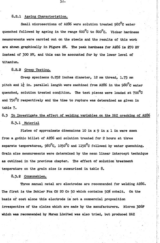
8.2 Material for investigation 8.2.1 Ageing characteristics 8.2.2 Creep testing
8.5 Investigation into the effect of welding variables on the HAZ cracking of A286
8.3*5 Bead on plate testing
8.3* ^ Assessment of HAZ cracking tendency 8.3.5 Grain size measurements
8.A Detailed microstructural and fractographic analysis of the nature of HAZ cracking in A286
8.4.1 Light microscopy
8.4.2 Electron micro-probe analysis
8.5 Detailed electron fractography and electron micro probe analysis
8.5.1 Replicas extracted from Zone I 8.5.2 Replicas extracted from Zone II
8 .6 Mechanism of HAZ cracking
EFFECT OF BORON ON THE HIGH TEMPERATURE WELD CRACKING RESISTANCE OF A286. 9*1 Introduction
9*2 Material for investigation 9*5 Mechanical properties
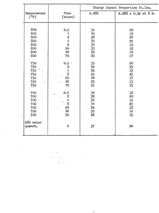
9.5*1 Ageing characteristics 9*5*2 Charpy impact properties 9*^ Bead on plate tests
9*5 Light microscopy
9*6 Grain size measurements ;
9*7 Electron fractography 9*8 Simulative welding trials , 9*8.1 Introduction
* 9*8.2 Material for investigation
9*8.5 Simulative welding heat treatments
9*8.4 Light microscopy ■ ■ t
9*8.5 Grain size determinations
12. RECOMMENDATIONS. 13. ACKNOWLEDGEMENTS. 14. REFERENCES.
LIST OF FIGURES.
Figure 1. Strain theory of hot tearing in castings (25).
Figure 2a. Ratio of interphase boundary tension and grain boundary tension as a function of the dihedral angle of the second phase0
Figure 2b. Effect of dihedral angle on the shape of liquid particles. Figure 3» Schematic representation of the two basic temperature ranges in
which a ductility minimum is conducive to weldment cracking. Figure 4. Possible mechanisms of cavity growth at grain boundaries. Figure 5« Classification of high temperature weld cracking.
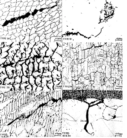
Figure 6. Weld metal solidification cracking (type 1A).
Figure 7* Schematic representation of the influence of the temperature
gradient in the liquid 11G" and the rate of growth "R".
Figure 8. Various forms of weld metal solidification cracking (type 1A).
Figure 9* The addition of ledeburite j(Fe^P) to a melt run in an l8CrlONi steel led to grain boundary penetration of the liquid phosphide and the resultant HAZ embrittlement.
Figure 10. Examples of apparently trans-granular cracking.
Figure 11. Effect of ghost boundaries in A1S1 304 (an l8Crl0Ni steel). Figure 12. type 2: Ductility Dip Cracking.
Figure 13* High temperature crack straddling the fusion boundary. X280.
Figure 14. The Fe-Ti-S ternary phase diagram.i ' '
Figure 15. Free energy of formation of binary sulphides.
Figure 16. Ageing characteristics of A286 after solution treatment 980°C water quench.
Figure 17 • Comparison of the 10,000 hours rupture strength of A286 with other commercial alloys.
Figure 18. Detailed illustration of the horizontally opposed tensile machine. Figure 19# Calibration of the range of travel speeds of the horizontally
Figure 21. Figure 22.
Figure 23.
Figure 24.
Figure 25.
Figure 26.
Figure 27.
Figure 28. Figure 29.
Figure 30*
Figure 31.
Figure 32. Figure 35®
Shows overall set up of tensile machine and the X-Y recorder. Electrical circuit for measurement of applied stress and extension.
Shows read out of applied stress against overall extension fori
a melt run.
Schematic representation of the set up for evaluating manual arc electrodes.
HAZ ductility dip cracking in A1S1 304 steel (l8Cr lONi steel).
X 270.
Relationship between applied stress to initiate HAZ ductility
dip cracking and grain size in A1S1 304 (l8Cr lONi stainless steel).
Relationship between overall extension at which HAZ cracking occurs and grain size in A1S1 304 (l8Cr lONi stainless steel). Graph of Vickers hardness plotted against ageing time for A286. Bead on plate testing of A286 using the W.R. K S10 experimental manual metal arc electrode.
Shows rosette shaped cavities associated with "Chinese script" orientated liquation phases in thw HAZ. Unetched. X 1000. HAZ liquation region associated with straighter edged cracking which is presumably wetted by the excess liquid. Uhetched. X750.
Non-metallic films in the HAZ of A286. Unetched. X 750.i
Shows HAZ cracks propagating normal, to the fusion boundary. Note their jagged morphology in the region of the fusion boundary and
their more straight edged morphology in the colder regions.r
Figure 34.
Figure 35*
Figure 36*
Figure
37-Figure 38,
Figure 39.
Figure 40.
Figure 41.
Figure 42.
Figure 43#
Shows detail of jagged shaped liquation cracks in the HAZ. Note their association with a titanium carbonitride particle. X 550. Shows the heavily microsegregated parent metal after etching in the selective mixed acids reagent. Note the strong remains of the dendritic structure of A286 even after heavy hot deformation.
(Selectively etched). X 25. ^
Shows the fusion boundary and HAZ in A286. The white etching regions are the interdendritic interstices which are locally enhanced in low melting point elements. (Selectively etched). X 150.
Detail of white .etching regions show that they are a preferential paths for crack propogation. (Selectively etched). X 300.
Showing rosette shaped liquation cracks in the white etching regions. (Selectively etched). X 480.
Shows liquation cracking associ&ted with titanium rich phase.
Compare with figures 30* 31* Unetched.
* O
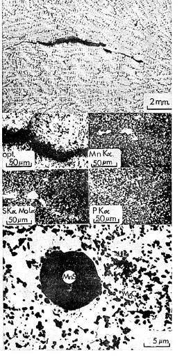
Shows the regions whichs liquate are enriched in Ti and Mo but they are not necessarily at grain boundaries where the cracks
initiate. '
Film like arrays of possible Y-phase (MgCS) or titanium sulphide v which are too thin to detect by electron-micro-probe analysis.
Shows the composition of the white etching region to be enhanced in titanium and nickel and depleted in iron and chromium.
(See figures 37 and 38)•
Figure 45*
Figure 46,
Figure 47.
Figure 48.
Figure 49* Figure 50. Figure 51 • Figure 52. Figure 53. Figure 54.
Figure 55*
Figure 56.
Figure 57c
microscope-micro- analysis also indicates Ti and S.
Dendritic sulphides of titanium indicated by electron-micro-scope-micro- analysis.
Dendritic Ti^-S^ selected area electron diffraction pattern indexed sheet 2 Appendix 1.
Selected area electron diffraction indicates the particles are dendritic arrays of M^C. Sheet 3# Appendix 1.
Detail of M^C in the HAZ of A286. (See figure 49 and sheet 3# Appendix 1) for selected area electron diffraction pattern. Indexed diffraction pattern of [ooi] zone of M^C.
Shows liquated iron titanium phase.
Electron-microscope-micro-analysis indicates Fe-Ti phase. Dendritic liquated Fe-Ti phase.
o
Liquated Fe-Ti phase associated with thermal faceting.
Unsolved selected area electron diffraction pattern of Fe-Ti phase. Possibly a [123] zone of the F.C.C. crystal Appendix 1 Sheet 7.
Show titanium vanadium carbosulphide ( Y-phase) in HAZ of A286. This particular region is near the fusion boundary.
Shows detail of titanium vanadium sulphide or carbosulphide (Y -phase) in the HAZ of A286,
Selected area electron diffraction pattern indicates |000l]
Figure 58.
Figure 59*
Figure 60.
Figure 6l.
Figure 62,
. Figure 63.
Figure 64. Figure 65*
Figure 66.
Figure 67.
Figure 68#
Figure 69. "Figure 70.
Figure 71* Figure 72.
Figure 73»
Shattered films. Electron-microscope-micro-analysis indicates Ti, V and S, probably Y-phase.
Shattered films. Electron microscope micro-analysis indicates Ti, V and S, probably Y-phase.
Y -phase or shattered films are seen by electron micro-probe analysis to consist of Ti, V and S.
Show fracture surface of colder region of HAZ (Zone II) which exhibits thermal faceting plus slip lines.
Detail of figure 61, thermal facets slip lines decorated with small titanium carbonitrides.
Thermal faceting in Zone II. v
s
Slip lines and thermal faceting in Zone II.
Shows the colder region (Zone II) of the fracture surface in the scanning electron microscope. Note the crack surface covered with slip lines.
Arrays of titanium carbonitrides.
Plot of Vickers hardness against ageing time at temperatures. Shows duplex austenite plus eutectic boride structure.
(Etched in Metharegia).
Shows detail of eutectic boride. X 2000. (Unetched). Shows brittle cracks propagating along eutectic boride. (Etched in Metharegia).
Electron micro-probe analysis of the eutectic boride.
Electron fractography reveals the dendritic morphology of the eutectic boride.
Figure 75• A286 after lj550°C heat treatment followed by 1 hour at 1^0°C
and air cooling. Note the much coarser grain size than Fig.74. The shape of the separations is not typical of weldment cracking. Figure 76. Shows dendritic particles in a burnt sample of A286. (1350°C
/
1 hour water quench).
Figure 77* Detail of a dendritic titanium vanadium particle in the burnt specimen of A286. (lj550°C 1 hour water quench).
Figure 78. Shows the fracture surface pf a crack in the burnt specimen of A286.
s
Figure 79* Detail of thermal faceting.
Figure 80. Composition of dendrit es in A286 after heat treatment at lj550°C. Figure 81. Composition of dendrites in the burnt specimens.
Figure 82. Shows dendritic particles probably carbosulphides in the burnt
specimen of A286. <
Figure .,©• Shows dendritic (FeTiV) sulphides possibly carbosulphides in the burnt specimens of A286i
Figure 84. Shows composition of eutectic boride by Electron Microscope micro-analysis.
v ■ ’
-’ ' J
• ■ !. G
SUMMARY.
On the basis of published work and the experimental results of this investigation, a detailed classification of high temperature weld
cracking is proposed. Two major types of cracking are recognised: lype 1 -separations along boundaries decorated with liquated second phase resulting from microsegregation, (solidification cracking in the weld metal and
liquation cracking in the HAZ (Heat Affected Zone) ): Type 2 - separations associated with relatively clean grain boundaries caused by grain boundary sliding in the solid state and they are synonymous with creep rupture. This form of cracking is referred to as ductility dip cracking because it is believed to be associated with a ductility minimum which occurs in some alloys.
In order to study high temperature weld cracking in detail, a reliable and reproducible means of producing cracks is required. To fulfil this need, an experimental horizontal tensile machine was designed and constructed. The high temperature weld cracking resistance is expressed in terms of the applied stress and overall extension necessary to initiate cracking. Using this apparatus, the effect of grain size on the HAZ (Heat
Affected Zone) cracking of AISI JOk (an l8Cr lONi non-hardenable austenitic
steel in which the grain boundaries are free to migrate) was investigated. A linear relationship between applied cracking stress and the reciprocal of the square root of the grain size was found. This is consistent with the cracking theories.
short. Detailed light and electron microscopy complemented by electron-micro- probe- analysis revealed the cracking mechanism to be two stage: Initiation by liquation (type 1) and propagation by a solid state creep
rupture process (type 2). A 0.59 *rt# boron addition to the basic composition of A286 was found to improve the cracking resistance by refining the parent metal grain size and making the steel more resistant to grain coarsening during welding. The boron was also found to alter the elemental
solidification sequence of A286 and it avoids the formation of the white
etching hot short regions. ^
1. GENERAL INTRODUCTION,
Austenitic nickel-chromium steels have excellent corrosion resistances and elevated temperature properties and they are used extensively in the
chemical and power generating industries* Modern plant requirements have resulted in the development of steels with improved creep resistances (i.e. increased resistance to time dependent hot deformation which often results in a decrease in the resistance to high temperature cracking. This has led to an increase in the incidence of cracking during casting, hot working and welding and the application of these alloys has therefore been limited.
During fusion welding of creep resistant alloys a complex form of cracking may take place both in the heat affected zone (HAZ) and in the weld metal. The cracking is always intergranular and it is generally referred to by such terms as hot tearing and hot cracking. In austenitic steels the cracks may be so small (micro-fissures) that they are not detected by non destructive testing. However, the cracks can be sufficiently extensive to provide notches and preferential corrosion paths for premature failure in service. The lack of knowledge of the mode of formation and the methods of eliminating intergranular cracking coupled with the cost of weldment failures were the main reasons for commencing this programme of work.
Unfortunately an ambiguous terminology has evolved to describe
weldment cracking and the first task of this investigation is to systematically classify the possible forms of high temperature cracking based on the
combination of mechanical and metallurgical factors. The mechanical factor takes the form of the shrinkage stresses and strains induced during the welding thermal cycle and the metallurgical factor is influenced by the degree of micrpsegregation and the grain size. It is known that both weld metal cracking end heat affected zone (HAZ) cracking are often caused by liquid films which wet the grain boundaries and embrittle the steel. Both the mechanical and metallurgical factors can be adjusted. A suitable pre heat will reduce the thermal strains whereas a fine grain size and a
restriction in the amount of impurities will increase the high temperature cracking resistance. The introduction of a second phase such as delta ferrite or the eutectic boride may also reduce the incidence of cracking by reducing the grain size.
? In the literature describing the various methods of estimating the hot cracking resistance, no single method has been universally accepted. An alternative method of assessing the hot cracking resistance of steels has been developed in this investigation. This necessitated the construction of a horizontally opposed tensile machine of original design. The test
consists of loading a test plate in the machine, to a stress at which cracking occurs during welding. The cracking is reflected by an increase in the extension of the test specimen. It is believed that this test procedure is a more sensitive and reproducible means of assessing the high temperature weld cracking resistance of steels than tests which rely on the difficult and debatable measurement of crack length.
' , ?
steel is coarse grained is weld cracking a problem. The experimental tensile machine was used to investigate the effect of grain size on the high
temperature weld cracking of this steel. By sharp contrast A286 is an intermetallic strengthened, 25Ni, 15Cr steel, in which the grain boundaries are not free to migrate and cracking is most likely during fusion welding. The various methods of reducing cracking in this steel have been fully investigated. Detailed light microscopy, electron microscopy complemented by a electron micro-probe-analysis have provided the evidence to postulate a cracking mechanism.
A 0.39 wt$6 boron addition was found to improve the high temperature
weld cracking resistance and the reasons for the beneficial effects of boron are described. The full details of the literature survey and the experimental results are contained in the following report.
CHAPTER 1. CRACKING TERMINOLOGY.
1.1 Introduction.
The general phenomenon of ferrous and non-ferrous alloys exhibiting low ductility when stressed in the vicinity of their solidus temperature has been a problem since the early days of metal manufacture. Over the years, as each stage of metal production has developed, an ambiguous often confusing terminology has evolved to ^describe the same intergranular cracking. In the casting bay, cracking is referred to by such terms as Ingotism and Panel
Cracking (l). Unfortunately, these terms only convey the location of cracking alpng the flat faces of the ingots and they do not indicate their
hot deformation of metals, intergranular cracks often form and terms such
as Hot Shortness (4), Hot Short Cracking, (8, 20), Forge Cracking (8), Over
heating (5*6) and Burning (5*6) are used. When the intergranular fracture surfaces have a dull appearance the fracture is said to be Matt-Faceted (7)* Burnt steels when fractured show a texture which is often referred to as
"Coaky" (8) in appearance. In nickel base alloys during hot working the
surfaces of the metal may exude a silicon rich liquid phase which is described as "Freckle Formation" (9)* In the manufacture of tin bronzes and grey cast irons a similar effect is referred to as "Tin Sweat" (3*10) when a tin rich liquid containing sulphur and phosphorus exudes from the cast surfaces.
1.2 Terminology used in Welding Literatures.
Unfortunately the technology of welding has developed later than casting and hot working industries and the evolution of the various terms to describe intergranular cracking has bee^f insular. It is therefore not surprising to find a whole new range of technical jargon to describe the same basic form of intergranular cracking. As with the other stages of metal production original descriptive terms have evolved such as Crater Cracking (11), Star Cracking (11), Root Notch Cracking (11) and Underbead Cracking (11). In the special case of electroslag welding, which is basically a continuous casting process, the cracking which occurs at the start and the finish of welding is described as the Start and Finish Defect
(12). This form of defect is not unlike the Piping (13) whioh occurs
direction is thought important (14) and terms such as Longitudinal cracking and Centre-line cracking refer to cracks propagating in the direction of welding whereas the term Transverse Cracking applies to cracks propagating normal to the welding direction. Size is considered to be relevant and terms such as Macro-Cracks for the large cracks and Micro-Cracks or Fissures for small cracks are used. Radiography has also evolved a descriptive term for the type of intergranular cracking which appear to ignore the welding direction and terms such as Check Cranking (14) or Multi-Directional Cracking (14) are often used.
Since the various technologies have developed separately, it is not surprising to find such a confusing terminology. In an attempt to place welding on a more scientific basis, terms such as Hot Tearing (15,16), Hot Cracking (17)* Super-Solidus Cracking (17,18) and Sub-Solidus Cracking
(17,18) have been applied. According to the Welding Institute (15)* heat affected zone hot tears can be distinguished by the following characteristics:
(i) The path of hot tears is always intergranular with respect
to the prior austenitic grains.
(ii) Hot tears are usually accompanied by redistribution of metallic inclusions and the formation of arrays of non-metallic particles at prior austenite grain boundaries. (iii) Hot tears form short microcracks often confined to a portion
of the prior austenite grain boundary and seldom exceeding a few prior austenite grain diameters in length.
(iv) Hot tears can be observed in the heat affected zones having ferritic-pearlitic microstructures which would not be expected to show cold cracking.
"Hot tears can always be distinguished by their discontinuity, i.e. the irregular and jagged appearance of the crack, and often the connection of small unconnected ruptures. They are interdendritic and follow the
dendritic solidification pattern. The surfaces of hot tears are oxidized and discoloured and they may exhibit decarburization and a coarse dendritic structure".
From these two descriptions it is obvious that the word *Hot Tearing1 has a different meaning to different people, and it is in the welding literature
( where the confusion exists because this term has been used for mary years in the foundry industry. Even though there are major discrepancies between the respective definitions, there are basic similarities. For example, both cracks are associated with microsegregation, formed at high temperature, and they are intergranular.
To help clear up this apparent confusion Borland (l7)proposed a generalised theory on which cracks which form in weld metals and castings in the presence of a liquid films are referred to as Super-Solidus Cracks. Brockhurst and Muir (18) have extended this classification to distinguish three main types of cracking which are as follows:
(1) Rupture occurring at temperatures which are above the equilibrium solidus temperature of the alloy concerned. This can be referred to as "hot tearing".
(3) Rupture may also occur at temperatures which are sufficiently low to eliminate the possibility of a liquid phase. Failure may be due to the presence of solid phases of low ductility, or to the operation of creep deformation mechanisms. This form of cracking may be referred to as "stress rupture", "creep rupture" or "hot brittleness".
There is evidence to suggest that the first two modes of rupture involve very similar mechanisms. The distinction between them may be based partly on the morphology of the crack - hot tears being more jagged than hot cracks and partly on the fact that hot tearing is "super-solidus" while hot cracking is "sub-solidus" cracking, at least as far as the main
intentional constituents of the alloy are concerned. In both cases the fracture path is intergranular". From Brockhurst and Muir*s analysis, temperature is the main criterion on which to classify cracking. At high temperature (super-solidus) hot tearing occurs in the presence of f a liquid phase whereas in the fully solidified mass hot cracking occurs
at some (sub-solidus) temperature and at even lower temperature stress
rupture occurs. The issue is even further confused by Hull (19) who
considers hot cracking to only occur at "super-solidus" temperatures. In the authorfs opinion this commitment to a time at temperature is unnecessary and impracticable, and this is the weakness of using
temperature as the classification parameter.
In an attempt to rationalize a classification of cracking Kammer et al (14) have proposed that the appearance and their condition of
unambiguous classification of high temperature cracking which the author
CHAPTER 2. THEORIES OF HIGH TEMPERATURE WELDMENT CRACKING,
2.1 Introduction ,
The theories of hot cracking are not very well developed. Many of these theories are of a foundry technology origin and they have been modified to explain weldment cracking. The theories may be divided into two basic groups. In the first main group, the SOLID-LIQUID THEORIES, the effect of a low melting point liquid spreading along a grain boundary is considered. From the observations of weldment cracking, the solid-liquid theories are far more likely to explain the type 1 cracking, as explained in Table 2. At temperatures which are sufficiently low to exclude the possibility of intergranular liquids, the cracking can be accounted for by the second main group; the SOLID STATE THEORIES. Such theories are
related to creep rupture and are relevant to type 2 ductility dip cracking
as summarised in Table 2.
2.2 Requirements of a Comprehensive Cracking Theory.
A theory of cracking must be related to practical circumstances and it should be valid over the high temperature range ( >0.5 Tta,where Tm is the melting point in °K). The theory should predict the conditions by which the two basic cracking types form and also explain the relative significance of liquated films, solid films, thermal faceting, and slip lines on the crack surfaces. Finally, a comprehensive theory should take into account the various physical parameters which may influence the mode of cracking. They are as follows
(1) Property of the intergranular microsegregates.
fracture stress, grain size and the surface energy of the crack over the high temperature range.
(3) High temperature properties of the alloy.
The relative intergranular strength to intragranular strength for a given alloy and the tendency of the grain boundaries to slide or migrate over the high temperature range.
Needless to say, no comprehensive theory of weldment cracking has been proposed. It is beyond the scope of this chapter to deal in great detail with standard theories of high temperature cracking which are
contained in numerous reviews (14,17*20,21) but to give a’brief outline of
the main theories which have been proposed. 2.5 Group 1 - Solid-Liquid Theories.
2.5*1 Descriptive Theories
Three main pictorial theories of cracking have been developed on the basis of observations of solidifying castings. All three propose that cracking is due to mechanical and metallurgical factors. The mechanical factor increases as the restraint or hindrance to contraction increases whereas the metallurgical factor is the formation of intergranular micro-segregates in the form of liquid films.
(a) The Shrinkage Brittle Theory (22,25)
This theory has been mainly used to describe the cracking of solidifying castings but ,it can be suitably modified for a weld metal. Hie sequence of solidification is as follows:
(ii) A solid skin first forms by rapid cooling. Solidification cracks form at the weakest point, the solid-liquid interface, and are healed by the remaining liquid. Dendrites nucleate and grow but a coherent network is not formed.
(iii) As the temperature decreases further, a coherent network of cells or dendrites is formed. Since the weldment is restrained the shrinkage stresses developed may exceed the rupture stress of the cored weld metal and solidification cracks can form. The cracks cannot be healed because the solidification structure is torn apart and there is insufficient liquid available for healing.
In the case of large castings and electroslag welds where there may be a hot spot (high temperature region), the shrinkage stresses are greatest and the cracking is most pronounced. Van Eeghem (24) has extended this theory to include cracks which form in the solid state along the
impurity enriched prior austenite grain boundaries. (b) Strain Theory of Pellini (25)
This theory proposes that cracking is due to the high strains which are set up by the steep temperature gradients and these tend to pull apart solid masses separated by a continuous film of liquid. Like the shrinkage brittle theory cracking occurs at or near the bulk solidus. A schematic drawing of the solidification sequence leading to cracking is shown in Figure 1.
(c) Borlands Generalised Theory (17)
Stage 3 Grain boundary development
Stage 4 Complete solidification
The theory proposes that during stages 2 and 3 cracking occurs but
liquid healing may take place in stage 2, whereas in stage 3 the dihedral
angle is important. A low contact angle will give a small solid to solid contact area and high stresses can build up which can result in cracking.
2.3*2 Interfacial Energy - Dihedral Angle Relationships (26)
Smith (26) has suggested that the distribution of a liquid particle at a grain boundary depends on the interfacial energies between the liquid and the solid. The interfacial or surface energies operating can be
approximated to simple surface tension or surface forces and by simple geometry (triangle or forces).
YSS - YLS cos e/2
YLS 1
T m YSS " 2 cos 0/2
where *s the solid-liquid interface energy
fQQmmmm... *s grain boundary solid-solid interface energy
$ ---- -is the dihedral angle
r ...is the ratio of the solid-liquid interface energy
YLS to the solid solid interface energy Ygg*
The relative interface energy ratio can be measured in terms of the dihedral angle of the solid-liquid interface as shown in the Figure 2a, 2b. Smith et al have shown by micro-radiography that:
(l) When l80° > 0 < 60° the liquid takes the form of isolated particles on
(2) When 0 m 60° the liquid forms a continuous film around the grain edges.
(3) When 6 < 60° the liquid film spreads out over the grain faces as
the angle decreases giving complete coverage at 0 * 0.
2.30 The Saveiko Model (27)
Saveiko has suggested that a solidifying casting is analogous to a set of glass blocks separated by water films. The force necessary to separate these two blocks of glass is given by the relationship.
p «
Ay
...
(2)
gb
where: p is the force
7 is the surface energy
A is the surface area
& is the value for gravity
b is the film thickness
2<0.4 Liquid Filled Crack Theories (2900,3102)
All the liquid filled theories of cracking relate applied stress to initiate cracking with a surface energy term. This is the basis of the Griffith*s crack criterion which postulates the existence of pre-existing cracks.
•p
f - (c“)
where: f - stress required to propagate a crack of length C
7 - surface energy of the fractured faces
and Eborall et al (29) have proposed that these are effectively crack nuclei or notches having no strength. The presence of these films reduces the solid-solid contact area which are the only regions possessing strength. Several workers (29-32) have applied similar relationships to the Griffith*s (28) criterion incorporating the effect of liquid films which reduces the surface energy term. According to Rostoker (30) and Stoloff (31) crack propagation can only be continued by the flow of liquid metal to the crack tip. If this passage of liquid ceases the crack is arrested.
All of the liquid filled crack models relate a fracture stress to a surface energy term and by a simple mathematical development, Williams (20) has related the fracture stress to the reciprocal of the square root of the grain size. This is in essence the relationship derived by Stroh (33) and
( McLean (3*0 for solid state creep cracking
JL
t - Y(|)a (20)
where: ~ f„ - fracture stress
K - constant dependent on dihedral angle
y - effective fracture surface energy (energy of the
exposed surface plus the energy due to plastic deformation at the tip).
D - grain size
2.3*5 Prohkorov Grain Boundary Displacement Mechanism (35)
on one another. Further deformation can only occur if the surface tension and the resistance to liquid flow is sufficient to accommodate the stresses required for plastic strain in the grains. The conclusions from this theory
are:-,(i) An increase in film thickness increases the fracture strain.
The work of Medovar (36) agrees with this conclusion.
(ii) A decrease grain size increases the fracture strain. This is also consistent with experimental findings in this report. (iii) A mixed grain size decreases the fracture strain. This is also
consistent with practical experience because the centre line of ingots where there can be the greatest variation in grain size is the most crack prone.
2.4 Summary of the Solid-Liquid Theories.
The descriptive theories (20*1) are of little scientific value and at best are only a pictorial representation of type 1 cracking. All three theories also overlook the possibility of the cracks initiating and propagating in the solid state along impurity embrittled grain boundaries. Such impurity decorated boundaries are known to promote intergranular separations in the solid state (temper brittleness) and Van Eegham (24) has evidence which indicates that a large percentage of cracking in solidifying castings occurs in the solid state.
The model proposed by Smith (26) has great practical importance especially when the last liquid to solidifying has a low melting point and spreads along the grain boundaries and can result in complete intergranular disintegration. An interesting example of this effect is caused by the addition of a small amount of phosphorus to the molten weld pool of an
cracking results. The model proposed by Smith (26) for weld cracking is a good start but disregards such important parameters as fracture stress and grain size.
The Saveiko (27) model (3*30) assumes that complete coverage of the grain boundaries takes place and the surface tension is the controlling factor. Ihis is not possible because according to the Smith model the surface tension depends upon the contact angle which in this case is always assumed to be zero. In practice, complete coverage does not take place and , the film thickness and the degree of spreading depend entirely on the
composition of the liquid. The theory once again ignores the relative effects of grain size, matrix strength, grain boundary strength, the relative rates of grain boundary sliding and migration. The important step this theory makes is the relating of stress with a surface energy term for crack formation.
to be a possibility there must be an excess of liquid to allow complete grain boundary coverage and grain boundary rotation. During welding this is most unlikely because there is insufficient time at temperature.
2.5 Group 2 - Solid State Cracking Theories (14,37*38)
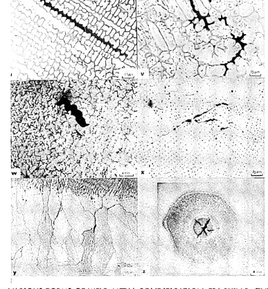
All the solid state theories are of a creep origin and the morphology of the cracks apply to the type 2 cracking. In general, solid state cracking theories indicate the formation of two main types of crack, wedge shaped cracks (w-type) and cavities due to grain boundary sliding because there is insufficient time for the vacancy condensation mechanism
(38) to take place. In general, relationships between temperature, strain
rate and type of fracture are very difficult to predict. The change from transgranular cracking to intergranular cracking depends upon several factors such as composition, microstructure, grain size and the relative degrees of grain boundary migration and sliding. Theories to explain how wedge shaped cracks and cavities form during welding can only be descriptive.
The plot of elongation against temperature for various alloys shows a ductility trough or dip at an intermediate temperature as shown in
Figure 3. At this intermediate temperature grain boundary sliding is
prevalent and both wedge shaped cracking and cavitation are believed (38)
to occur. Intergranular fracture is favoured by low strain rates, such as tensile testing. From practice, clean grain boundaries are found to increase the rupture life and elongation and therefore decrease the tendency to
intergranular fracture. Inclusions of the non-welding type are believed (38)
to be particularly effective in promoting intergranular cracking.
perhaps the most well known relationship of this type for wedge shaped
cracking. L
2
12. 7b. G
,
_ x
fff
- _ 7l" ■’ V f “T >
is the stress to initiate cracking (dynes per square cm).
7^ is the surface energy per unit area of crack formed along
a grain boundary. G is shear modulus.
L is length of sliding boundary,
r is shear stress (dynes per square cm).
According to creep theory the surface energy term 7^ must be less than
1000 dynes per square cm for wedge shaped cracking (33*34). 2*6 Summary of the solid state theories of cracking.
All the cracks which form in the solid state in weld metals or HAZ* s are caused by grain boundary sliding. A schematic representation of the possible mechanism of initiation and growth of cavities is shown in
)
[image:37.612.42.556.35.782.2]CHAPTER 3. CLASSIFICATION OF HIGH TEMPERATURE WELDING CRACKS IN ALLOTS.
3*1 Introduction
In chapter 1 the confused state of the terminology regarding hot cracking was described and the various methods of crack classification were presented. It is obvious there is a need for a clear and unambiguous
terminology for cracking and, in this chapter, an attempt is made to present a concise classification of cracking. The classification is based on the original terminology co-authored with Boniszewski and Eaton (39) but it has been further simplified and modified to include the results of this investigation.
3»2 Appraisal of Classification Parameters.
The extensive literature describing high temperature cracking is confused by an ambiguous terminology. Unfortunately the situation is further oonfused because each individual stage of metal production has a different term to describe the same intergranular rupture. Classifications of high temperature weld cracking are usually based upon the temperature of formation, location and size, which only lead to further confusion.
Temperature is not applicable because the cooling rates during welding are steep, and it is impossible to attribute cracking to one particular
temperature. Location is unreasonable because weld metal cracking and heat affected zone cracking are thought to be fundamentally related. Size is unscientific because large cracks will undoubtedly consist of mixed fracture modes (40,47*51*96). The only reliable criterion on which cracks can be classified is their physical appearance which can be analysed by light
where Tn is the melting point in °K. In general the cracks are inter granular in the sense that they propagate along boundaries rather than across boundaries. During welding the strain rate and temperature at which cracking takes place are difficult to predict, but from creep theory low strain rates and high temperature favour intergranular rupture. There is no transgranular fracture in the strict sense of cleavage, although there is an isolated report of transgranular cracking taking place in austenite (41). The report of transgranular high temperature cracking could quite well be a mis-interpretation of cracking along ghost grain boundaries (Figures 10 and 11). Another form of high temperature, intergranular separation is the cavity which can link up to form cracks in both the weld
metal and HAZ0 In the majority of cases, cracking takes place when the
metal matrix has a face-centred cubic structure (e.g.) Nickel base alloys (42); Aluminium base alloys (43), Copper base alloys (44), and ferritic alloys which have an austenitic structure (45) at high temperature. The
%-; •
formation of intergranular cracking depends on two factors: the mechanical
factor (degree of restraint) and the metallurgical factor (the degree of• ?
microsegregation) and the relative influence of these two factors decides whether cracking occurs.
3.4 General Description and Definition of Cracking.
grains and the so-called "ghost" grain boundaries* and the loss of ductility is normally enhanced by the presence of boundary microsegrates in the form of films, inclusions and precipitates. There is no transgranular cracking, but cracks may appear transgranular where they form at ghost boundaries or where they propagate along newly migrated grain boundaries and thus cut across the solidification structure. As well as cracking, cavities are very often observed along the boundaries. In some areas the cavities
coalesce to form cracks. The relative influence of strain rate and temperature influences cavity formation. From these various considerations two main
types of intergranular weld cracking can be classified as shown in Table 2 and Figure 5*
3*5 Type 1: Cracking Associated with Microsegregation.
These consist of the boundary separations associated with micro segregation which may take the form of films, precipitates and inclusions. The microsegregation may consist solely of alloying elements or may be
completely impurity elements. In the majority of cases the microsegregation
is a mixture of impurities and intentional alloying elements (Figure 6).
The morphology of this form of cracking is characterised by a series of dis connected, jagged ruptures. Electron fractography carried out on this form of cracking may show dendritic films due to liquation and fast cooling, (Figure 43-46). Segregation cracking can further be sub-divided into types 1A and IB dependent on their location in the weld metal or the HAZ«
3.5*1 Type 1A: Solidification Cracking.
This is the most described form of boundary cracking, and it is now universally known as weld metal solidification cracking (16). Russian workers (46) use a similar term, "crystallization cracking" to describe the
same basic morphological form of cracking. In the past, terms such as hot cracking and hot tearing have been used, but these have caused much confusion and the term solidification cracking is preferred. The terms hot tearing and hot cracking may be used to describe the general phenomena of inter granular high temperature cracking, whereas the term super-solidous cracking (17) should be discontinued because it commits one to assuming that cracking occurs above the solidus temperature. This need not be the case, and Van Eegham (24) has evidence to show that solidification cracking occurs in
castings at a temperature at which they are fully solidified. Solidification cracks are seen to propagate along the impurity enriched prior austenite grain boundaries, and they appear in three basic morphological forms which
depend on the R /q ratio (48), where G is the temperature gradient and R is
the growth rate as shown in Figures 6 and 7* The more common crack
morphologies encountered in this investigation are shown in Figure 8u-8z. 3*5*2 Type IB: Liquation Cracking.
Liquation of low melting point constituents in the HAZ of alloys takes place during welding, and this can promote grain boundary embrittlement.
The term 1 liquation cracking* is proposed to describe this form of cracking because it infers the association of liquated films with the
mechanical deformation at high temperatures the as-cast structure may still persist. During welding any interdendritic low melting point microsegregates in the parent metal can re-liquate and HAZ cracking can result. Numerous phases can liquate based on the elements which extend the liquidus-solidus range of temperature (e.g., C, S, P, 0, N, B). Phosphorus rich liquids such as Ledeburite Fe^P easily wet the grain boundaries and are especially
embrittling, (Figure 9)* A special form .of liquation cracking.is the separations which can occur along ghost grain boundaries in steels which readily recrystallise during welding, (Figures 10 and 11).
3.6 Type 2; Ductility-Dip Cracking.
This type of cracking occurs along boundaries which are relatively "clean” in as much as they are free from liquated films. Cracking is assumed to occur at a temperature low enough to exclude liquid film formation. The
c
operative mechanism involved in this type of cracking are the relative amounts of grain boundary sliding and grain boundary migration. Grain boundary
sliding initiates cracking whereas grain boundary migration avoids crack propagation by blunting any cracks which form by leaving them stranded in the metal matrix. In many respects the intergranular separations resemble Stroh-McLean wedge cracks (33#54) and the cavities are similar to those
encountered in creep rupture. The cracks usually form normal to the principal stress and appear smooth edged and reflect the effect of tensile displacement by grain boundary sliding. Electron fractography carried out on this form of cracking shows a thermally faceted structure sometimes decorated with a small
dispersion of carbides as shown in Figure 63. Detailed electron fractography
steels. Bengough (49) has shown that this ductility dip is accentuated by a coarse grained steel. The probability of ductility dip cracking is also increased by a high intragranular strength compared with the intergranular strength which promotes grain boundary sliding. Ductility dip cracks can be sub-divided into two main types depending on their location in the weld metal or HAZ.
3.6.1 IVpe 2A: HAZ Ductility Dip-Cracking.
In the literature HAZ ductility dip cracks have been referred to by numerous terms. The morphology of cracking is not unlike the wedge shaped cracks and cavities observed during creep rupture. Typical
illustrations of these two types of ductility dip separation are shown in Figures 11, 12 and 25. In Figure 11 HAZ ductility dip cracking cannot be confused with liquation cracking because it occurs along the recrystallised .grain boundaries and ignores the ghost grain boundaries.
3.6.2 Type 3B: Weld Metal Ductility Dip-Cracking.
Similar shaped cracks have been observed in austenitic steel weld metals. The cracks are observed to ignore the solidification structure of the weld metal and they propagate along the migrated grain boundaries. Observations of this type of cracking have been reported (47#50-52) in A1S1 310 (25Cr20Ni steel) and it occurs in other austenitic steels. The
proposed. Typical illustrations of the wedge shaped nature of this form of cracking and the cavities are shown in Figure 12. Electron'fractography carried out on the surfaces of such cracks reveal slip lines# thermal facets and carbides but no liquation films (Figures 61-66).
3«7 Interaction of Types 1 and 2 Cracking.
It would be quite unreasonable to suppose that the two main forms of cracking do not interact. Careful optical microscopy can often reveal mixed cracking modes, (Figure 5) (40). Typical examples of the two main types of crack interacting are as
follows:-(a) Solidification cracks (1A) propagating as ductility dip cracking (2B) (40) (Figure 5). This form of cracking often occurs in multi run welds. Fracture surfaces examined from this type of cracking show both liquated films, slip lines thermal facets decorated with inclusions.
(b) Solidification cracks (1A) and weld metal ductility dip cracks (2B) often straddle the fusion boundary to propagate as HAZ liquation cracks (IB) and HAZ ductility dip cracks (2A) (Figures, 9# 12) • (c) In A286 steel initiation of cracking can occur by a liquation of
mechanism (IB) and propagation by a ductility dip along l,clean,, grain boundaries (2A). Cracks having this morphology are quite common in the HAZ of creep resistant alloys, Figure 5*
(d> Ghost grain boundaries have been reported to produce mixed modes of fracture. Crack initiation can occur in the ghost grain boundary and propagation along the "clean" recrystallised boundaries (see Figure 11).
3 .8 Summary of the Classification.
films are observed on the replicas, cracking is of the type 1, solidification cracking (1A) in the weld metal and liquation cracking (IB) in the HAZ.
Should the replicas exhibit an absence of films and relatively clean fracture surface, showing thermal facets, a fine dispersion of carbides and possibly slip lines then the"cracking is of the type 2. It is obvious that types 1 and 2 forms of cracking will often merge and replicas may show both thermal facets and liquated films. The term "ductility dip" used to describe type 2 cracking is not entirely satisfactory because of the complication of wedge shaped cracks, cavities, and the conditions by which they form. However, they are similar to creep cracks and are broadly associated with the
ductility dip which occurs at intermediate temperatures in ductile alloys. The exact position of the fusion boundary and HAZ are still subjects of conjecture (42). An example of such a complication is shown in Figure 8z where cracking occurred in the epitaxial growth region. This form of cracking can be safely classified as type 1 but whether it occurs in the weld metal or HAZ may be arguable.
3*9 Conclusions.
On the basis of microscopic evidence two main types of cracking can be classified which can be sub-divided into four specific types.
Type 1; Boundary cracks associated with microsegregation. Type 1A: Weld metal solidification cracking.
Type IB: HAZ liquation cracking.
HAZ ductility dip cracking.
y 4.1 Introduction.
During World War II an age hardening austenitic steel with excellent creep ductility was developed by Krupp in Germany. The steel was to be used in the aircraft industry for elevated temperature application, and was named
’Tinidur*. In i960 Allegheny Ludlum, U.S.A., patented (55) a steel of
similar composition named A286 which was also strengthened by titanium rich intermetallic compounds. Today this steel is known by numerous codes, some of which are as follows
A1S1 616, (U.S.A.)., A286 (U.S.A.)., F.V.559 (Firth Vickers, U.K.)., G.68 (Jessop-Saville, U.K.)., (54).
Unfortunately, the application of A286 has been limited because it is not readily fusion welded without the formation of HAZ cracks. The
incidence of HAZ cracking has been found to be more pronounced in thick sections rather than in fine grained thin sheet. The application of A286 has, therefore, been limited to thin sheet which is relatively easily T.I.G. fusion welded.
4.2 Chemical Composition.
A286 is made under licence in the U.K. by Jessop-Saville and is known as G68. In the literature numerous chemical compositions are quoted and the data sheet (54) for G68 gives the following specification in weight percent.
Carbon 0.08
Manganese 1.55
Silicon O.95
Chromium 15*5
Molybdenum 1.25
Titanium 1.9
Vanadium 0.52
Aluminium 0.20
Iron balance
The steel can be described as an austenitic iron, nickel, chromium alloy strengthened by additions of molybdenum, vanadium, titanium and aluminium. The ratio of titanium to aluminium may vary depending on the ageing
characteristics required. Titanium and aluminium combine during ageing to
form a coherent gamma prime ( 7') precipitate which imparts the creep
strength. The manganese level is always maintained below 1.55 wt# because titanium is a stronger desulphurizer and there is no advantage having larger amounts. Boron is also added in small amounts (0.005 - 0.015 wt$) to further improve the creep ductility but it can be argued that such low levels are always present as trace elements.
4.5 Steelmaking.
A286 cannot be made by air melting because the titanium reacts with the oxygen and nitrogen in the atmosphere to produce a dirty steel. Some form of vacuum melting is required and the CEVAM process (consumable electrode vacuum arc) has been successfully used by Jessop-Saville Limited (55). In the CEVAM process an air melted or powder metallurgy ingot serves as an electrode which is consumably melted under vacuum in the furnace. Air
melted ingots are hot short and they have a low transverse ductility (56).
non-hardenable austenitic steels such as A1S1 This is because A286 is designed to resist hot deformation and obviously more force is required during forging and hot rolling. Cracking in A286 often occurs because too high a reduction in cross section area is attempted for a particular pass. If too high a forging temperature is used 1300°C, liquation of an inter metallic compound occurs which is reported (57) as a Laves type phase.
Blum and Witt (58) have identified the Fe-Feg Ti eutectic which forms at
1290°C and solid solution elements will further reduce the liquation temperature. At 1250°C a liquid phase rich in nickel, titanium and silicon (Ni^Ti^Si^) has also been reported to form (57) which can lead to cracking. The formation of these small droplets of liquid at the surface of the billets during hot working is known as ’'freckle formation".
4.5 Physical Metallurgy.
The commercial development of intermetallic strengthened nickel-base alloys (59*60) and iron-nickel-chromium nickel-base alloys (61,62) has
stimulated great interest in the possible precipitation reactions. In all these alloys the hardening mechanism is associated with the precipitation of a face centred cubic phase known as gamma prime ( 7 f) of chemical
composition (Ni^(A Ti)). This phase is always associated with a peak hardness
of 500 H.V. Mihalisin and Decker (63) have reported that the maximum
response to hardening can be produced by varying the aluminium to titanium
ratio which alters the lattice parameter of gamma prime ( 7*) and therefore
Solid Solution-►Zones — ► V Equilibrium precipitate or
Overaged precipitate.
Similar reactions take place in A286 and these have been described in detail (62). Bty varying the aluminium to titanium ratio the peak hardness is
varied and the ageing rate can be retarded or enhanced. During ageing, hot deformation and welding, numerous phases can form which can be divided into two main groups. Group 1 consists of the phases which impart precipitation hardening or dispersion hardening of the austenitic matrix, and Group 2 are the embrittling phases.
4.5*1 Group 1. Strengthening Phases.
Gamma Prime 7 1.
This is the principal hardening phase which appears as sub-micro scopic spheriods and has the general formula N^(A1 Ti). The structure of gamma prime is f.c.c. and the lattice parameter is altered by the Al to Ti ratio, (a « 3*59 toe units). In certain compositions Ni^(Al Ti) can be extremely stable and it is the principal phase during overageing.
Ni,Alj
This is similar to gamma prime ( 7 ,*) but is ordered, i.e., a superlattice, with the nickel atoms occupying the cube faces and aluminium the cube corners.
Ni^Ti (77) eta phase
This phase appears after the ageing peak and has a hexagonal
structure with lattice spacings a « 2.5454 kx units and c « 2.829 kx
units.
NiAl and Ni(Al Ti)
precipitate when the Al to Ti ratio is over 2.6. Wilson (6l) has reported that Ni(Al Ti) rapidly forms during overageing and is unsatisfactory because it does not impart any strengthening.
Nig(Al Ti) Heusier lype Phase (62)
With Al to Ti ratios of unity Nig(Al Ti) can form in the overaged o
structure. The lattice parameter of this phase is 5.8,5 A which is
approximately twice that of bcc NiAl • Like (Ni(Al Ti) this phase grows rapidly and does not impart much strengthening.
4.5.2 Group 2. Non-Strengthening Phases.
The non-strengthening elements usually embrittle the grain boundaries.
G. Phases (Ni^TigSi^ and Ni^Si^Ti^)
This is a complex f.c.c. phase based on the Ni-Si-Ti system. Several compositions have been reported, (57*60).
Laves Phase MgTi
The equilibrium diagram for iron titanium suggests that Feg^i can form at 70 wt^iron whereas the compound FeTi forms at 50 wt# iron. According to Blum and Witt (58), A286 is difficult to weld because of the formation of an Fe - Fe^Ti eutectic which wets the grain boundaries in the HAZ and induces cracking. The structure and composition of this phase was carried out by analyses on bulk residues. This technique is inadequate because the presence of other compounds in the residue complicate chemical analysis, while the formation from X-ray powder patterns is not sufficient to establish the structure uniquely. The melting point of the Fe-Fe^Ti eutectic is 1290°C
and Gemmill (65) has reported that the iron can be replaced by silicon and