Real-Time Octree Generation
from Rotating Objects
Richard Szeliski
Digital Equipment Corporation
Cambridge Research Lab
Digital Equipment Corporation has four research facilities: the Systems Research Center and the Western Research Laboratory, both in Palo Alto, California; the Paris Research Laboratory, in Paris; and the Cambridge Research Laboratory, in Cambridge, Massachusetts.
The Cambridge laboratory became operational in 1988 and is located at One Kendall Square, near MIT. CRL engages in computing research to extend the state of the computing art in areas likely to be important to Digital and its customers in future years. CRL’s main focus is applica-tions technology; that is, the creation of knowledge and tools useful for the preparation of impor-tant classes of applications.
CRL Technical Reports can be ordered by electronic mail. To receive instructions, send a mes-sage to one of the following addresses, with the word help in the Subject line:
On Digital’s EASYnet: CRL::TECHREPORTS
On the Internet: [email protected]
This work may not be copied or reproduced for any commercial purpose. Permission to copy without payment is granted for non-profit educational and research purposes provided all such copies include a notice that such copy-ing is by permission of the Cambridge Research Lab of Digital Equipment Corporation, an acknowledgment of the authors to the work, and all applicable portions of the copyright notice.
The Digital logo is a trademark of Digital Equipment Corporation.
Cambridge Research Laboratory One Kendall Square
Cambridge, Massachusetts 02139
Real-Time Octree Generation
from Rotating Objects
Richard Szeliski
Digital Equipment Corporation
Cambridge Research Lab
CRL 90/12 December 21, 1990
Abstract
The construction of a three-dimensional object model from a set of images taken from
different viewpoints is an important problem in computer vision. One of the simplest ways
to do this is to use the silhouettes of the object (the binary classification of images into
object and background) to can construct a bounding volume for the object. To efficiently
represent this volume, we use an octree, which represents the object as a tree of recursively
subdivided cubes. We develop a new algorithm for computing the octree bounding volume
from multiple silhouettes, and apply it to an object rotating on a turntable in front of
a stationary camera. The algorithm performs a limited amount of processing for each
viewpoint, and incrementally builds the volumetric model. The resulting algorithm requires
less total computation than previous algorithms, runs in real-time, and builds a model whose
resolution improves over time.
Keywords: Computer vision, 3-D model construction, image sequence (motion)
anal-ysis, volumetric models, octrees, silhouettes, computer aided design, computer graphics
animation.
Contents i
Contents
1 Introduction: : : : : : : : : : : : : : : : : : : : : : : : : : : : : : : : : : : 1
2 Octree models of shape : : : : : : : : : : : : : : : : : : : : : : : : : : : : : 3
3 Hierarchical octree construction from multiple views : : : : : : : : : : : : 4
4 Image silhouette intersection tests : : : : : : : : : : : : : : : : : : : : : : : 6
5 Synthetic model results : : : : : : : : : : : : : : : : : : : : : : : : : : : : : 8
6 Complexity analysis : : : : : : : : : : : : : : : : : : : : : : : : : : : : : : 11
7 Image Preprocessing : : : : : : : : : : : : : : : : : : : : : : : : : : : : : : 13
7.1 Adaptation and thresholding : : : : : : : : : : : : : : : : : : : : : : : : 14
7.2 Orientation estimation : : : : : : : : : : : : : : : : : : : : : : : : : : : 14
7.3 Camera parameter calibration : : : : : : : : : : : : : : : : : : : : : : : 17
8 Real image results : : : : : : : : : : : : : : : : : : : : : : : : : : : : : : : 19
9 Extensions: : : : : : : : : : : : : : : : : : : : : : : : : : : : : : : : : : : : 21
10 Discussion : : : : : : : : : : : : : : : : : : : : : : : : : : : : : : : : : : : : 23
A Serial and parallel half-distance transforms : : : : : : : : : : : : : : : : : 27
1 Introduction 1
1
Introduction
This paper describes a new approach to creating 3D models of objects from multiple views.
In our scenario, an object rotates on a turntable in front of a static camera. We use only
the silhouettes—the binary classification of each image into object and background—to
compute a bounding volume for the object. This algorithm enables us to obtain a quick and
rough model of the object in real-time. This model can be used in conjunction with a more
sophisticated shape-from-motion algorithm that relies on the detailed analysis of optic flow,
which is presented in a companion report [Szeliski, 1990]. In this context, it serves both as
an initial model for shape refinement, and as a non-linear (bounding volume) constraint on
the final shape.
The automatic acquisition of 3-D object models is important in many applications. These
include robotics manipulation, where the object must first be described and/or recognized
before it can be manipulated; Computer Aided Design (CAD), where automatic model
building can be used as an input stage to the CAD system; and computer graphics animation,
where it can facilitate the task of an animator by giving him easy access to a large catalog of
real-world objects. All of these applications become much more interesting if the acquisition
can be performed quickly and without the need for special equipment or environments.
The problem of building octree models from multiple views has a long history in
the computer vision field. Octrees were first introduced as an efficient representation for
geometric models by Jackins and Tanimoto [1980] and Meagher [1982] (see also [Carlbom
et al., 1985]). A good survey of octree representations can be found in [Samet, 1989], and
a survey of construction and manipulation techniques in [Chen and Huang, 1988].
The construction of volumetric description from multiple views was first described
by Martin and Aggarwal [1983] (the representation used was a collection of “volume
segments”). Chien and Aggarwal [1986b] constructed an octree from three orthographic
2 1 Introduction
Ahuja [1986]. Hong and Shneier [1985] and Potmesil [1987] both used arbitrary views and
perspective projection. In both of these papers, an octree of the conic volume formed by the
silhouette and the center of projection is computed for each viewpoint, and the octrees from
all of the viewpoints are then intersected. Both approaches project the octree cubes into
the image plane to perform the object/silhouette intersection. In contrast to this, Noborio
et al. [1988] and Srivastava and Ahuja [1990] perform the intersections in 3-space, which
eliminates the need for perspective projection. Both of these approaches use a polygonal
approximation to the silhouette. Additional research has also been done on building octrees
from range data [Chien et al., 1988] and the recognition of object models from octrees
[Chien and Aggarwal, 1986a].
The new approach described in this paper was designed with two goals in mind: to
process each image as it arrives (real-time), and to produce a coarse model quickly and
refine it as more images are seen (incremental). A secondary goal of this research is to
find highly parallelizable algorithms. Our approach is similar to Potmesil’s [1987], but
instead of building a separate octree for each view, we intersect each new silhouette with
the existing model. More importantly, we do not build a full-resolution octree after each
view. Instead, we build a coarse octree description first, and then refine it as the object
continues to rotate in front of the camera. This makes our approach similar to other recent
incremental algorithms [Matthies et al., 1989]. As we will see, this approach significantly
reduces both the individual computation per image and the total computation performed,
since less cubes are generated and tested.
Our approach also uses a very efficient 2-D image plane intersection test based on
bound-ing squares and the chess-board distance transform [Rosenfeld and Kak, 1976] (Potmesil
uses a quadtree or non-overlapping rectangle description). The 3-D projection operations,
computation of the distance transform, and bounding box intersection test are easily
par-allelizable, and can thus take advantage of modern massively parallel architectures. The
2 Octree models of shape 3
floating-point microprocessors.
We begin the paper in Section 2 with a brief review of the octree representation. In
Section 3, we describe how our algorithm hierarchically constructs an octree. In Section 4,
we describe our fast image plane intersection test. In Section 5, we show some results of
our algorithm operating on synthetically generated images. We analyze the complexity of
our algorithm in Section 6. In Section 7, we switch gears and discuss a number of practical
image processing issues: silhouette computation (adaptive thresholding), the automatic
determination of turntable position, and the calibration of the camera position. This leads
up to some results obtained from real images (Section 8). In Section 9, we discuss a number
of extensions, including moving the camera and repositioning the object on the turntable.
We close in Section 10 with a comparison between our new algorithm and other approaches.
2
Octree models of shape
An octree is a tree-structured representation that can be used to describe a set of binary valued
volumetric data enclosed by a bounding cube. The octree is constructed by recursively
subdividing each cube into eight sub-cubes, starting at the root node (a single large cube).
Each cube in an octree can be one of three colors. A black node indicates that the cube is
totally occupied (all of its data = 1), and a white node indicates that it is totally empty (all
of its data = 0). Both black cubes and white cubes are leaf nodes in the tree. A gray cube
lies on the boundary of the object and is only partially filled. It is an interior node of the
tree and has eight equally sized children of different colors. Figure 1a shows a graphical
view of a small octree, and Figure 1b shows its associated colored tree representation.
Octrees are an efficient representation for most volumetric objects since there is a large
degree of coherence between adjacent voxels (volume elements) in a typical object. A
number of schemes have been developed to efficiently represent and encode octrees [Chen
4 3 Hierarchical octree construction from multiple views
0 4
2 10
61 60
10 60 61
[image:10.612.97.517.71.261.2]0 2 4
Figure 1: A simple two-level octree and its tree representation
cubes at a given resolution level are kept in the same array. Each cube explicitly represents
itsx, y, andzcoordinates, as well as its color and a pointer to the first of its children (for a
gray cube). This representation is well suited to the commonly occurring operations in our
algorithm. In particular, it enables the fast projection into the image of all the cubes at a
given resolution level.
3
Hierarchical octree construction from multiple views
Our basic algorithm constructs the octree in a hierarchical coarse-to-fine fashion. For a given
octree resolution, the inner loop of the algorithm carves out a 3D volume incrementally
from a sequence of silhouettes. After one complete revolution of the object, those cubes
whose color is still uncertain are subdivided. Because the octree is completely constructed
at one resolution before refining the next one, a minimum of extra cubes that eventually get
trimmed off are created.
In more detail, we start each new revolution of the object on the turntable with a
collection of black cubes all at the given (finest) resolution level; to initialize the algorithm,
we start either with a single black cube, or with a small collection (e.g., 888) of black
3 Hierarchical octree construction from multiple views 5
are known to lie outside of the object, and gray cubes are ambiguous (this is different from
the usual octree coloring scheme, where gray cubes are known to have children of differing
colors). For each new image that is acquired, we project all of the current cubes into the
image and test whether they lie totally within or outside of the silhouette (Section 4). We
then update the color of each cube according to the following table:
old color)
test result+ black gray white
inside black gray white
ambiguous gray gray white
outside white white white
Note that cube colors can only change from black to gray or white, or from gray to white
(i.e., the volume is “carved away”).
For our hierarchical approach to work, the tests of projected cubes against the silhouettes
can be crude, but they must not classify a cube as wholly inside or outside unless this is
certain. Projected cubes that are erroneously classified as “ambiguous” will be colored gray
(unless they are already white), and the decision as to their true color will be deferred to
the next finer resolution level. This allows our intersection tests to be more sloppy and also
makes our algorithm more robust against noise.
After one resolution level has been processed completely, i.e., the object has been seen
from all of its views (which usually corresponds to a complete revolution), we refine the
gray cubes by splitting them into eight pieces. The new cubes are initially colored black
and are then processed as were the cubes at the previous resolution level. Note that since
all of the possible views are used before proceeding to the next level, there is no need to
update nodes that belong to levels coarser than the one currently being analyzed. If we
wish to save storage space, we can go back later and compact the octree by converting gray
6 4 Image silhouette intersection tests
4
Image silhouette intersection tests
To make the above approach practical, we must have an efficient way to project the octree
cubes into image-space coordinates and to test for intersection with the object silhouette.
The perspective projection step is not a critical computational bottleneck, since it is trivially
parallelizable, and specialized hardware exists to perform it [Clark, 1982]. In our current
implementation, we simply project all eight corners of each cube using floating point
arithmetic.
An opaque cube projected into the image plane will in general form a six-sided polygon.
Performing an accurate test of this hexagon against the silhouette (which we represent as
a binary image) can be quite time consuming. Instead, we use a coarser test based on the
hexagon’s bounding box, which may sometimes fail to detect a true inclusion or exclusion.
This is acceptable in our overall framework, since this kind of “mistake” simply colors a
cube gray, thus deferring the decision to the next finer resolution level.
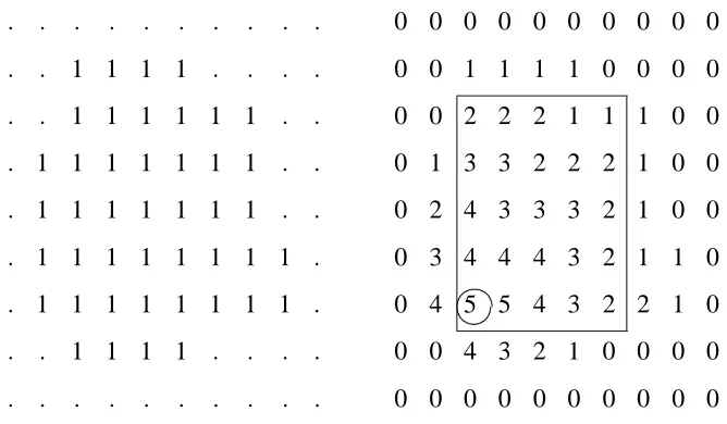
More precisely, each projected cube is converted into a bounding square. This allows
us to do the inclusion and exclusion tests using a single lookup into two distance maps
constructed from the silhouette and its complement. These distance maps are one-sided
versions of the chess-board distance transform [Rosenfeld and Kak, 1976]. Each point in the
distance map contains the size of the largest square starting at that pixel that fits completely
within the silhouette (Figure 2). These half-distance transforms for the silhouette and its
complement can be computed using a single raster-scan pass over the image, or using
an O (logd) step parallel algorithm, where d is the diameter of the largest region in the
silhouette (Appendix A).
One final minor detail which must be resolved is how to compute the bounding square
from the bounding box of the projected cube (which is defined by the minimum and
maximum projected x and y values). We could center the bounding square over the
4 Image silhouette intersection tests 7
: : : : : : : : : :
: : 1 1 1 1 : : : :
: : 1 1 1 1 1 1 : :
: 1 1 1 1 1 1 1 : :
: 1 1 1 1 1 1 1 : :
: 1 1 1 1 1 1 1 1 :
: 1 1 1 1 1 1 1 1 :
: : 1 1 1 1 : : : :
: : : : : : : : : :
0 0 0 0 0 0 0 0 0 0
0 0 1 1 1 1 0 0 0 0
0 0 2 2 2 1 1 1 0 0
0 1 3 3 2 2 2 1 0 0
0 2 4 3 3 3 2 1 0 0
0 3 4 4 4 3 2 1 1 0
0 4 5 5 4 3 2 2 1 0
0 0 4 3 2 1 0 0 0 0
0 0 0 0 0 0 0 0 0 0
[image:13.612.139.473.248.443.2]
Figure 2: The half-distance transform and its use in inclusion testing. A sample binary
image is shown on the left, and its half-distance transform on the right. The circled 5 in the
distance map indicates that a 55 square is the largest square inside the silhouette whose
8 5 Synthetic model results
have chosen the latter approach, testing both bounding squares for possible inclusion or
exclusion, since this will more often result in a successful test.
5
Synthetic model results
To determine the viability of our new algorithm and to quantify its performance, we decided
to first test it on a series of synthetically generated images. Our test models were constructed
by combining superquadric parts [Pentland, 1986; Solina and Bajcsy, 1990]. The models
were rendered from a variety of viewpoints using a 3-D graphics modeling system. The
rendered images, along with the simulated turntable orientation and camera position, were
then given to the octree building program. The complete simulation system was run on-line,
which enabled the observation of the simulated input images and resulting octree models
simultaneously.
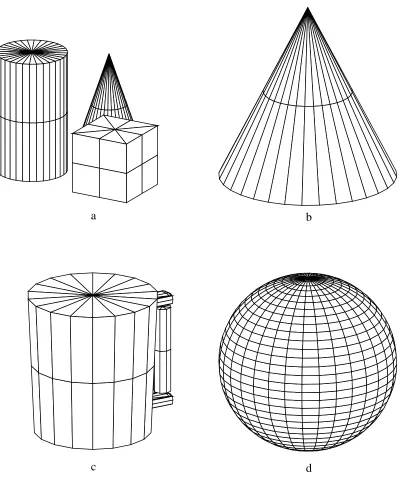
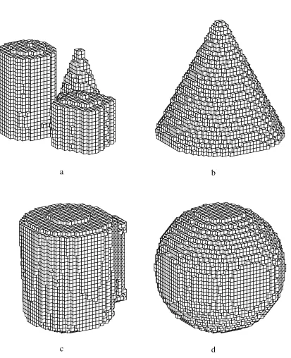
Figure 3 shows four of the superquadric models that we used. Figure 4 shows the
corresponding octree models constructed from 32 evenly spaced views (11 increments).
For these simulations, the camera was at 4.0 (times the cube size) from the object center,
the inclination (from horizontal) was 20 , and the field of view was 30 . The octrees shown
are rendered at 323 resolution, even though they were computed to 643 resolution. As we
can see from these examples, the shape of these objects is recovered fairly well, although
there are occasional “bulges” on some flats sides of the objects (due to a limited number of
viewpoints) or at the top (unavoidable from this camera position).
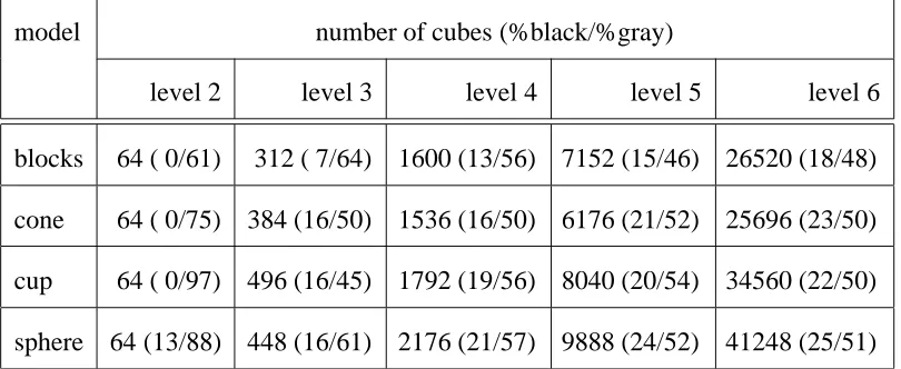
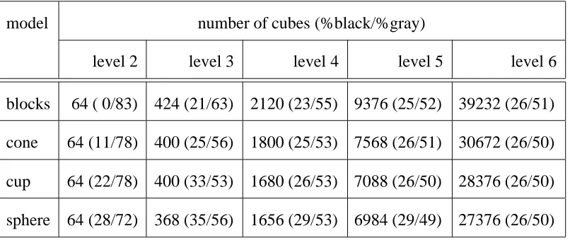
To obtain a more quantitative measure of the algorithm’s performance, we counted the
number of cubes of each color created at each resolution level. As we can see from Table
1, at the finer levels, roughly 25% of the cubes are black, 25% are white, and 50% are gray.
Since each gray cube gets split into eight children, the number of cubes roughly quadruples
at each level. This is consistent with Meagher’s [1982] finding that the number of cubes is
5 Synthetic model results 9
a b
[image:15.612.104.505.163.640.2]c d
10 5 Synthetic model results
a b
[image:16.612.110.523.135.643.2]c d
6 Complexity analysis 11
We can verify if this is true by computing the surface area of each of the test objects
(Table 2). Note that the flat areas at the bottom of the objects do not contribute significantly
to the octree cube count, but do add significantly to the surface area. To verify the “accuracy”
of our octree construction, we can compare the total volume of the octree with that of the
original synthetic model (Table 2), as was done in [Veenstra and Ahuja, 1986; Potmesil,
1987; Srivastava and Ahuja, 1990]. For most of the volumes, these figures compare
favorably, despite the restricted range of viewpoints.
6
Complexity analysis
The hierarchical octree construction algorithm developed in this paper is designed to operate
in close to real-time. It should therefore perform less computation for each image acquired
than previous approaches such as Potmesil’s, and hopefully perform less computation in
total. In practice, this is what occurs, because instead of building a complete octree from
each image, only those cubes already on the surface of the model are refined.
As we saw previously, the expected number of cubes for an octree is proportional to
its surface area (for a sufficiently smooth object). For most objects, this should be smaller
than the surface area of the viewing cone formed by the camera and the object silhouette.
To see if this occurs in practice, we can count the number of cubes in the octrees formed
from a single silhouette (Table 3), which tells us the number of cubes in a viewing cone.
Compared to the octree cube count from our hierarchical octree algorithm (Table 1), we see
that the single-view count generally exceeds the 32-view count. The exception is for large
simple objects that fill most of the octree volume.
This comparison only gives us a rough idea of the computation performed by both the
hierarchical approach and the previous single resolution methods. For our hierarchical
algorithm, the amount of processing required is proportional to the number of cubes at the
12 6 Complexity analysis
model number of cubes (%black/%gray)
level 2 level 3 level 4 level 5 level 6
blocks 64 ( 0/61) 312 ( 7/64) 1600 (13/56) 7152 (15/46) 26520 (18/48)
cone 64 ( 0/75) 384 (16/50) 1536 (16/50) 6176 (21/52) 25696 (23/50)
cup 64 ( 0/97) 496 (16/45) 1792 (19/56) 8040 (20/54) 34560 (22/50)
[image:18.612.105.510.164.330.2]sphere 64 (13/88) 448 (16/61) 2176 (21/57) 9888 (24/52) 41248 (25/51)
Table 1: Cube counts for octrees computed from synthetic models (32 views)
model cube count analytic area octree volume analytic volume
blocks 35648 2.3844 0.1685 0.1552
cone 33856 2.5321 0.2643 0.2601
cup 44952 2.9734 0.3445 0.3102
sphere 53824 3.1278 0.5267 0.5190
[image:18.612.130.482.467.611.2]7 Image Preprocessing 13
model number of cubes (%black/%gray)
level 2 level 3 level 4 level 5 level 6
blocks 64 ( 0/83) 424 (21/63) 2120 (23/55) 9376 (25/52) 39232 (26/51)
cone 64 (11/78) 400 (25/56) 1800 (25/53) 7568 (26/51) 30672 (26/50)
cup 64 (22/78) 400 (33/53) 1680 (26/53) 7088 (26/50) 28376 (26/50)
[image:19.612.107.510.121.291.2]sphere 64 (28/72) 368 (35/56) 1656 (29/53) 6984 (29/49) 27376 (26/50)
Table 3: Cube counts for octrees computed from synthetic models (single view)
updated. For the older octree algorithms, we must first construct an octree corresponding to
the new view (in time proportional to the total number of cubes in all of the levels of Table
3), and then intersect this tree with the previously estimated object tree. The intersection
algorithm ends up creating and deleting cubes all over the octree hierarchy, which makes
its implementation on a parallel machine much more difficult.
Compared to the older octree intersection algorithms, our new hierarchical approach
results in a much simpler and more parallelizable algorithm. For scenes of moderate to high
complexity, it can result in dramatically lower computation (both per frame and overall)
because the complete viewing cones arising from the silhouettes are not constructed. To
better compare the performance of our new technique with the old approach, we will have
to implement the intersection of viewing cones algorithm, which we have not yet done.
7
Image Preprocessing
Before we can apply our shape from silhouette algorithm to real image sequences, we must
14 7 Image Preprocessing
silhouette computation (object/background segmentation), the determination of turntable
rotation, and the calibration of camera position.
7.1
Adaptation and thresholding
To compute the silhouette, we first adapt the imaging system to the background scene without
the object by acquiring a few dozen images and computing the minimum, maximum, mean,
and variance values at each pixel. With our current setup, we can perform this computation
in near real-time (0.6 frames/second). These measurements are then used to precompute a
range of normal values for each background pixel. When thresholding the image, any pixel
falling outside of this range is assumed to be part of the object.
This adaptation stage is also used for a second purpose. To facilitate the automatic
estimation of turntable rotation, we attach a black-and-white binary-coded strip onto the
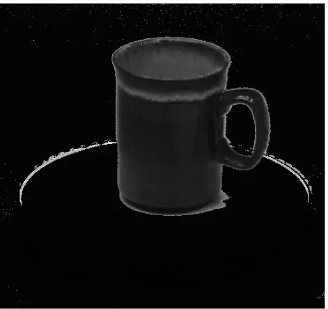
edge of the turntable (Figure 5 and Appendix B). During the adaptation stage, we allow
the turntable to turn at its natural speed. For each pixel that is part of this position coding
ring, we see both the black and white values. Because of the larger than usual variance,
we can classify these pixels as part of the position encoding system and select a good
threshold for each binary code pixel. The thresholding stage that computes the object
silhouette thus classifies each image into four categories: black binary code, white binary
code, background, and object (Figure 6).
7.2
Orientation estimation
To estimate the current orientation (rotation angle) of the turntable, we look at the binary
code pixels in the classified image. We choose a small number of columns (currently 32)
horizontally centered around the middle of the image, and in each column find the widest
strip of adjacent binary code pixels. We then find the 8-bit binary code corresponding to the
7.2 Orientation estimation 15
16 7 Image Preprocessing
Figure 6: Thresholded image: black binary code = dark gray, white binary code = light
7.3 Camera parameter calibration 17
and convert it into a value between 0 and 255. The sequence of binary patterns follows a
Gray code, since only one bit changes at a time. This prevents an inconsistent code from
arising from several bits changing asynchronously (which may occur due to camera noise
or if the binary code is not perfectly vertical in the image). The binary values from all of
the columns are averaged to obtain a position estimate that has better than 8-bit resolution
(about 0:1 accuracy). This number, normalized to a 0 to 360 range, is the output of our
turntable position estimator.
7.3
Camera parameter calibration
Before the object acquisition system can be run, we must determine the camera parameters,
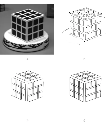
i.e., the camera position, orientation, and focal length. We do this using a known reference
model placed on the turntable (Figure 7a) [Caprile and Torre, 1990]. First, we extract the
edges by finding the zero crossings in the band-pass filtered image and using the gradient of
the filtered image to compute the edge orientations and to throw away weak edges (Figure
7b). Next, we use the Hough transform with gradient directions [Ballard and Brown, 1982]
to find the straight lines in the image (Figure 7c). Finally, these lines are used to compute
the camera parameters relative to the reference cube [Caprile and Torre, 1990].
To compute the camera parameters relative to the center of rotation of the turntable
(which is our desired object-centered coordinate frame), we must look at the reference cube
from a number of viewpoints (i.e., while the cube is rotating on the turntable). We could
at this stage also use Sawhney’s [1990] method for simultaneously computing the cube
structure and the cube rotation to do our calibration. Since we have not yet implemented
this portion of our calibration procedure, we use a simpler method. We measure the camera
distance to the object by hand and then compute the other camera parameters from the major
and minor axes of an ellipse fitted to the image of the turntable top. This simplified method
18 7 Image Preprocessing
a b
[image:24.612.93.495.134.601.2]c d
Figure 7: Camera parameter computation: (a) calibration cube (b) edges extracted (c) lines
8 Real image results 19
The overall sequence of steps involved in pre-calibrating the system is thus fairly
simple. With the turntable rotating, a sequence of images without any objects is taken. This
memorizes the default background and the location of the binary code. A reference model
is then placed on the turntable and the camera position automatically determined (currently
we use the shape and position of the turntable top). This last stage could conceivably be
replaced by a set of calibration points permanently fixed to the turntable. The result is a
system that can be operated by a na¨ıve user such as a CAD designer or graphics artist.
8
Real image results
We have tested our algorithm on a number of real image sequences. Figure 5 shows a
sample image of a cup sitting on the turntable. Applying the adaptation and classification
techniques described previously, we obtain the thresholded image shown in Figure 6. For
this image sequence, it was necessary to lower the thresholds in the bright white areas
of the adaptation image, because the shadows cast by the cup were causing an incorrect
classification (most of the turntable top would be classified as part of the object). As we can
see from the thresholded image, the algorithm still misclassifies isolated background pixels
as foreground. Conversely, some of the specularities on the cup have been misclassified
as background. Using a small amount of propagation and shrinking [Rosenfeld and Kak,
1976] should help remove these problems. A better long-term solution would be to use
color images, since there is less chance of confusion, and since shaded regions (going from
dark to light) are not forced to cross the background color.
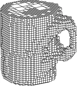
Figure 8 shows the final model constructed from the cup image sequence. The final
reconstruction captures the overall shape of the cup quite well. The major source of errors
in the reconstruction is due to the specularities that cause erroneous gray nodes in the middle
of the model (these are not visible in Figure 8, which renders gray nodes at the lowest level
20 8 Real image results
9 Extensions 21
9
Extensions
There are a number of efficiency optimizations that could be added to our algorithm. To
reduce the cost of the cube corner projections, there are several techniques that we could
use:
1. cache the projections, since each corner is usually used more than once;
2. project only one corner, and used fixed vectors to define the other seven corners;
3. use recursive subdivision of the projected octree cubes to obtain the image coordinates
of the points at the desired resolution.
Note that these last two approaches do not generate the exact corner positions, but this is
perfectly acceptable, so long as a larger bounding box results.
We could further reduce the number of cubes projected by examining only visible cubes.
This would remove from consideration both the cubes on the back side of the object and
also those interior to the object (cubes that are not on the surface). It would then only be
possible to remove a single layer of cubes at a time, and a hole in the object would require
several views to “eat its way through” the object.
Adding gray level or color mapping onto the cubes in the octree would enhance the
realism of the reconstruction. However, this is not an easy task, since many different
intensities could map to a single cube, both within a single frame and between frames
[Potmesil, 1987]. We could also use this stage to check for inconsistencies, such as white
cubes that become visible later on.
Our octree construction algorithm would be more powerful if we could change the
position of the camera and/or the object. The former case is easier to handle. We simply
re-calibrate the system, and continue processing with the new camera parameters (we
could also use more than one camera simultaneously). An interesting empirical question
22 9 Extensions
refinement), or whether we should process just the finest level—or maybe even the whole
tree—for each new silhouette. The pure hierarchical algorithm described in this paper
could then be replaced with a more flexible control strategy, which would decide how many
whole or part levels to process depending on the real-time constraints imposed by the rate
of incoming images.
The change in object orientation caused by repositioning it on the turntable is also simple
to handle if the object motion is known. In this case, we can transform the octree to its
new orientation [Ahuja and Nash, 1984; Weng and Ahuja, 1987] and continue processing
as before. An example of such a known transformation would be if the object had only a
few stable poses. Determining the object motion from the volumetric data itself is more
difficult [Chien and Aggarwal, 1986a], especially when both the old and new object models
contain areas that are extraneous. This remains an interesting area of future research.
One final interesting area of research is the interaction between the bounding volume
generated by this algorithm and the deformable surface model computed from optic flow
[Szeliski, 1990]. In this complementary approach to shape from rotation, knowledge of the
optic flow and object motion provides a sparse and somewhat noisy estimate of points on the
object’s surface which are integrated using an elastic surface model. The bounding volume
described by the octree can certainly provide inequality constraints on the deformable
model, but can it also provide unambiguous surface positions in certain cases? Each ray
from the camera passing through a pixel inside the silhouette must hit something opaque
inside at least one of the black cubes in its path. In the general case, this occupancy
constraint is complicated to represent and use. A more practical approach is to track the
silhouette over three or more frames to estimate the location and curvature of points on the
10 Discussion 23
10
Discussion
Given the current performance of our algorithm, is it fair to call it a “real-time” method?
The microwave turntable that we use to rotate our object turns at 0.5 revolutions per minute.
The time to acquire, process, and display a 512480 image on our workstation is about 1.7
seconds per frame for adaptation and thresholding, and 3.0 seconds for an incremental octree
construction step of moderate complexity (including the display of the current model). This
means that we can process about 40 views per rotation, which is perfectly adequate for
obtaining a bounding volume.
Ideally, we would like to speed up the turntable rotation (and the processing) by a
factor of 10. This should be achievable with the next generation of faster RISC processors.
Because our algorithm is essentially data parallel (both at the pixel and cube levels), it
would be easy to obtain true real-time performance with a SIMD parallel machine.
A more important question might be: is our system useful and easy to use? Compared
to previous octree construction algorithms, our new hierarchical approach requires less
computation because it only examines those cubes close to the surface of the object. It
provides a coarse model of the octree rapidly, which improves as the object continues to
rotate in front of the camera. Compared to the alternatives of manually entering a model
using a 3-D pointer or using structured light, our system is easier to use and requires
less equipment. However, it still has the same limitation as previous silhouette-based
algorithms, such as a limited precision and the inability to detect concavities in the object.
To be truly useful, our method will have to be combined with more sophisticated shape
from motion algorithms that track surface markings on the object. As part of such a shape
from rotation system, it can quickly and automatically provide 3-D shape descriptions of
24 10 Discussion
References
[Ahuja and Nash, 1984] N. Ahuja and C. Nash. Octree representation of moving objects.
Computer Vision, Graphics, and Image Processing, 26:207–216, 1984.
[Ballard and Brown, 1982] D. H. Ballard and C. M. Brown. Computer Vision.
Prentice-Hall, Englewood Cliffs, New Jersey, 1982.
[Caprile and Torre, 1990] B. Caprile and V. Torre. Using vanishing points for camera
calibration. International Journal of Computer Vision, 4(2):127–139, March 1990.
[Carlbom et al., 1985] I. Carlbom, I. Charkravarty, and D. Vanderschel. A hierarchical data
structure for representing the spatial decomposition of 3-D objects. IEEE Computer
Graphics and Applications, 5(4):24–31, 1985.
[Chen and Huang, 1988] H. H. Chen and T. S. Huang. A survey of construction and
manipulation of octrees. Computer Vision, Graphics, and Image Processing, 43:409–
431, 1988.
[Chien and Aggarwal, 1986a] C. H. Chien and J. K. Aggarwal. Identification of 3D objects
from multiple silhouettes using quadtrees / octrees. Computer Vision, Graphics, and
Image Processing, 36:256–273, 1986.
[Chien and Aggarwal, 1986b] C. H. Chien and J. K. Aggarwal. Volume/surface octrees
for the representation of three-dimensional objects. Computer Vision, Graphics, and
Image Processing, 36:100–113, 1986.
[Chien et al., 1988] C. H. Chien, Y. B. Sim, and J. K. Aggarwal. Generation of
vol-ume/surface octree from range data. In IEEE Computer Society Conference on
Com-puter Vision and Pattern Recognition (CVPR’88), pages 254–260, IEEE ComCom-puter
Society Press, Ann Arbor, Michigan, June 1988.
[Clark, 1982] J. H. Clark. The geometry engine: a VLSI geometry system from graphics.
10 Discussion 25
[Giblin and Weiss, 1987] P. Giblin and R. Weiss. Reconstruction of surfaces from profiles.
In First International Conference on Computer Vision (ICCV’87), pages 136–144,
IEEE Computer Society Press, London, England, June 1987.
[Hong and Shneier, 1985] T.-H. Hong and M. O. Shneier. Describing a robot’s workspace
using a sequence of views from a moving camera. IEEE Transactions on Pattern
Analysis and Machine Intelligence, PAMI-7(6):721–726, November 1985.
[Jackins and Tanimoto, 1980] C. L. Jackins and S. L. Tanimoto. Oct-trees and their use in
representing three-dimensional objects. Computer Graphics, and Image Processing,
14:249–270, 1980.
[Martin and Aggarwal, 1983] W. N. Martin and J. K. Aggarwal. Volumetric description
of objects from multiple views. IEEE Transactions on Pattern Analysis and Machine
Intelligence, PAMI-5(2):150–158, March 1983.
[Matthies et al., 1989] L. H. Matthies, T. Kanade, and R. Szeliski. Kalman filter-based
algorithms for estimating depth from image sequences. International Journal of
Computer Vision, 3:209–236, 1989.
[Meagher, 1982] D. Meagher. Geometric modeling using octree encoding. Computer
Graphics, and Image Processing, 19:129–147, 1982.
[Noborio et al., 1988] H. Noborio, S. Fukada, and S. Arimoto. Construction of the octree
approximating three-dimensional objects by using multiple views. IEEE
Transac-tions on Pattern Analysis and Machine Intelligence, PAMI-10(6):769–782, November
1988.
[Pentland, 1986] A. P. Pentland. Perceptual organization and the representation of natural
form. Artificial Intelligence, 28(3):293–331, May 1986.
[Potmesil, 1987] M. Potmesil. Generating octree models of 3D objects from their
silhou-ettes in a sequence of images. Computer Vision, Graphics, and Image Processing,
26 10 Discussion
[Rosenfeld and Kak, 1976] A. Rosenfeld and A. C. Kak. Digital Picture Processing.
Aca-demic Press, New York, New York, 1976.
[Samet, 1989] H. Samet. The Design and Analysis of Spatial Data Structures.
Addison-Wesley, Reading, Massachusetts, 1989.
[Sawhney et al., 1990] H. S. Sawhney, J. Oliensis, and A. R. Hanson. Description and
reconstruction from image trajectories of rotational motion. In Third International
Conference on Computer Vision (ICCV’90), pages 494–498, IEEE Computer Society
Press, Osaka, Japan, December 1990.
[Solina and Bajcsy, 1990] F. Solina and R. Bajcsy. Recovery of parametric models from
range images: the case for superquadrics with global deformations. IEEE Transactions
on Pattern Analysis and Machine Intelligence, 12(2):131–147, February 1990.
[Srivastava and Ahuja, 1990] S. K. Srivastava and N. Ahuja. Octree generation from object
silhouettes in perspective views. Computer Vision, Graphics, and Image Processing,
49:68–84, 1990.
[Szeliski, 1990] R. Szeliski. Shape from Rotation. Technical Report 90/13, Digital
Equip-ment Corporation, Cambridge Research Lab, December 1990. For ordering
informa-tion, please send a message to [email protected] with the wordhelp in the
Subject line.
[Vaillant, 1990] R. Vaillant. Using occluding contours for 3D object modeling. In First
European Conference on Computer Vision (ECCV’90), pages 454–464,
Springer-Verlag, Antibes, France, April 23–27 1990.
[Veenstra and Ahuja, 1986] J. Veenstra and N. Ahuja. Efficient octree generation from
silhouettes. In IEEE Computer Society Conference on Computer Vision and Pattern
Recognition (CVPR’86), pages 537–542, IEEE Computer Society Press, Miami Beach,
Florida, June 1986.
A Serial and parallel half-distance transforms 27
representation and efficiency. Computer Vision, Graphics, and Image Processing,
39:167–185, 1987.
A
Serial and parallel half-distance transforms
Our octree construction algorithm uses the half-distance transform to test the bounding
boxes of projected cubes against the silhouette images. The half-distance transform is a
one-sided version of the chessboard distance transform [Rosenfeld and Kak, 1976]. Given
a binary image, it computes for each pixel the size of the largest all ones square starting at
that pixel.
The serial version of the algorithm computes
f (1)
(ij)=min(f (0)
(ij)1+ min (u v)2N3
f (1)
(i+uj+v))
in reverse raster order, wheref (0)
(ij)is the input binary image, andN3=f(01)(10)(11)g.
A simple parallel version of the algorithm can be drived from the PD algorithm described
in [Rosenfeld and Kak, 1976, p. 356]
f (m+1)
(ij)=f (0)
(ij)+ min (u v)2N
4
f (m)
(i+uj +v)
whereN4 =f(00)(01)(10)(11)g. This algorithm takes dsteps to converge, where
dis the diameter of the largest region (the maximum value in the distance map). A variant
on this algorithm is
f (m+1)
(ij)=min(f (m)
(ij)1+ min (u v)2N3
f (m)
(i+uj+v))
where initiallyf (0)
(ij)are set to 0 or1for pixels outside/inside the silhouette.
A quicker version of the preceding parallel algorithm uses 2 logdsteps
f (2m+1)
(ij) = min(f (2m)
(ij)s+ min (u v)2N2
f (2m)
(i+suj+sv))
f (2m+2)
(ij) = min(f (2m+1)
(ij)s+f (2m+1)
28 B Templates for Gray coded positioning ring and calibration cube
where s = 2m and N2 = f(01)(10)g. This algorithm doubles the distance to the
neighbors every two iterations.
If the number of parallel processor available is less than the number of pixels—for
example when using a MIMD machine or a smaller SIMD array—it pays to reduce the total
amount of computation performed. In this case, we can use a hierarchical version of the
parallel half-distance algorithm. We use the following pyramidal algorithm
f (2m+1)
(sxisyj) = min(f (2m)
(sxisyj)s+ min (u v)2N
2
f (2m)
(sxi+susyj+sv)) f
(2m+2)
(sxisyj) = min(f (2m+1)
(sxisyj)s+f (2m+1)
(sxi+ssyj+s))
in two fine-to-coarse-to-fine sweeps. In the first sweep, sy = 1, andsx = s = 2m going
up the pyramid and sx = s = 2
(2M;m)
going down, where M = log
2dis the height of
the pyramid. In the second sweep, the roles of sx and sy are reversed. This algorithm
first propagates the distances horizontally and diagonally, subsampling the points by 2
horizontally. The algorithm then repeats the procedure subsampling vertically. Because the
number of points being updated is reduced by 2 every 2 steps, the total number of operations
isO (n).
B
Templates for Gray coded positioning ring and
calibra-tion cube
Figures 9 and 10 show the patterns used for the 8-bit turntable position encoding ring
(suit-able for the 9”mini MICRO-GO-ROUND Rturntable) and the 400
4
00
calibration cube.
Both figures show the patterns at half scale. Full scale versions of these figures can be
ex-tracted from the PostScript version of this report. For information on how to obtain an
elec-tronic copy of this document, please send a message [email protected]
B Templates for Gray coded positioning ring and calibration cube 29
30 B Templates for Gray coded positioning ring and calibration cube
Figure 10: Pattern for calibration cube (1