DISKETTE DATA
ENTRY SYSTEM
DF11SYS
User's Guide
Version 2
March, 1976
Model Code No. 50135
DATAPOINT CORPORATION
The Leader in
Dispersed Data Processing
PREFACE
OFll provides a personalized data entry system for use on any OATAPOINT processor and diskette. OF!! is intended primarily to support generation of data entry systems on diskette. OFll
contains more features and greater capabilitie~ than OATAFORM 2 contained.
Forms" are created for display on the processor's screen, anu the data entry operator then simply fills in the form. The <.l(lta is then recorU8(J, (lnd at any time maY be ·retrieved and reviseu using the same form to view and edit the recorded data.
Each "form" is custom designed, and editing criteria are assigned to the data fields on the fom at the time the form is generated. Programs written in the high level OF11 language may also be assigned at this time. Forms and progrcims are then
combined ana become a unique OF11 system.
Three stages of development are involved in generating a
system: theeuitor and compiler are useJ to create fi.eld programs; the form yenerator i.s used to create forms; and the data entry interpreter is useJ to control data entry." Additionally, the print uti lity provides a hard copy listing of the ·jata tile, form
images, or .both
Since DF 11 uses standardized data record forma ts, fUrther
processing of the data can proceed under any OATABUS, BASIC, or
~PG program. Additionally, anyone of a number of av~ilable
communications programs or terminal emulators (including DATAPOLL
. and EM·2780) may be used to transmit DF11 data files for fUrther
processing at remote sites.
Chapter 1 should provide as much intorma tion about OF 11 as is
necessary for those familiar with both the cassette Version of
DATAFORM and DOS. Chapter 2 provides a more general description of
DFll, and continuing chapters descr tbe forms genera tion and da ta
entry using the forms. The DOS User's Guide, model number 50127,
provides more information about the DOS.
Throughout this manual, a field appearing between pOinted brackets, as:
<filename>
denotes a:r§9lJix.s1.Q field; whereas, a field appearing between square brackets, as:
[ , filename]
uenotes anQJ2tiQl)C!l field, whose use is explaine,d in subsequent uiscussion.
Ve,rsion 2 of DF11 contains the following'changes'from version 1 of DF 11:
1)
The execution of the CLOSE statement has ch~nged.2) The S type edit criteria has been added to suppress shift key inversion.
3) The interpreter's START command displays the name of the data file.
4) The default data file extensibn is TXT.
~) Keyin over-run is 'prevented.
b) Data tile OVERFLOW action has chanyed.
7) DFll interpreter now uses only 251 characters in a
disk sector, rather than 253.
This means that the
version
1interpreter must be used with version
1data files; and the version
2interpreter must,be
used with version
2data files.
8)
The
HELPcommana is no longer in the form
generator.
To convert
DF11version
1systems to
DFllversion
2systems,
each field program should be
re-comp~led,and each form should be
re-generated.
TABLE OF CONTENTS .
1.
A
QUICK GUIDE TO THE DISKETTE DATAFORM SYSTEM1.1 Installing the Diskette DATAFORM System 1.2 System Names
1.3 Program Gener~tion
1.3.1 Program Source File Creation 1.3.2 Program Compilation
1.4 Form Getieiation
1.5 Form Testing and Data Entry 1.6 Using DFll with. CHAIN
1.7 DF11 Compatibility
2. GENERAL DATAFORM TERMS AND CONCEPTS
2.1 What is a FORM?
2.2 What is a FIELD PROGRAM?
2.3 U~et Space and How It~s Allocated
2.4 :~ome Udta I::ntry Fedtures
J. 'l'Ul:!: FOJ{lVJ GENERATOR 3.1 Data.Field
3.2 Keyin Only Field 3.3 User Space
3.4 Form Horksheet 3.5 The NEW Command
3.5.1 Repeat Key (KEYBOARD)
·3.5.2 Cursor Movement Function Keys (2,4,6,8)
3.5.3 Character Insert Function K~Y (7)
3.5~4 Character Remove Function Key (0)
3.5.5 Erase Function Keys (1,.,9) 3.5.6 Lina Insert Function KeY (3)
3.5.7 Duplicate Character Function Key (5)
3.5.8 RetUrn to Monitor Functiori ~ey (CANCEL)
3.6 Assignment of Edit Criteria 3. 6.1 The TY PE Pa s s
3.G.l.l Alphabetic (A) 3.6.1.2 Digit (D)
3 . 6 . 1 . 3 N ume ric (r~) 3.6.1.4 Mixed (M)
'3.6.1.5 Numeric Minus-overpunch (0)
3.6.1.6 Shift Key Inversion (5)
3.6.2 The REQUIRE Pas~
J.6.2.1 Required (R)
3.6.2.2 Fill Controlled (F)
J.~.2.J Required and Fill Controlled (B)
v page 1-1 1-1 1-1 1-2 1-2 1-2 1-3 1-4 1-5 1,...6 2-1 2-1 2-2 2-4 2 -~)
3.6.2.4 Program Reserved (P)
3.6.2.5 Required and Program Reserved (S) 3.6.2.6 Keyin Continuous (K)
3.6.2~7 Required and Keyin Continuous (X)
3.6.3 The JUSTIFY Pass
3.6.3.1 Right Justify (J) 3.6.3.2 Zero Fill (Z)
3.~.3.3 Right Justify and Zero Fill (R)
3.6.4 The SEMI -CONSTANT and CONSTANT pa sse s J.6.5 The PROGRAM Pass
3.6.6 The LINK,Pass
3.6.6.1 Setting a Manual Link 3.6.6.2 Setting an Auto Link 3.6.6.3 Clearing a Link
3.7 The OUT Command 3.8 The REVISE Command 3.9 The OLD Command 3.10 The OS Command
4. THE COb1PILER 4.1 Labels
4.2 Flelu Program Names 4.3 Spaces
4.4 Comments
4.5 Specification Statements 4.5. 1 DATA
4.5.2 WORK 4.5. 3 COMf-10N 4. 5.4 RESERVE 4.5.5 EQU
4.5.6 REDEFINE 4.5.7 FIELD
4.6 Executable Statements
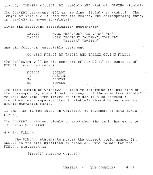
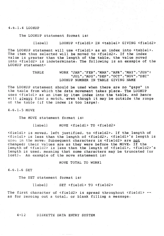
4.6.1 Transfers of Information 4.6.1.1 ALIGN
4.6.1.2 CONVERT 4. 6. 1. 3 F IELDNO 4.6.1.4 LOOKUP 4.6.1. 5 MOVE 4.6.1.6 SET
4.6.2
Ad~#Subtroct,
Multiply, Divide 4.6.3 The If Statement4.6.4 Output Control
4~6.4.1 BEEP
4.6.4. 6 Y~RITE 4.6.4.7 HEOF
4.6.4.8 READ
4.6.4.9 BACKSPACE
4.6.4.10 DELETE
4.6.4.11 PEOr
4.6.5 Transfers of Control
4.6.5.1 GOTO
4.6.5.2 CALL and RETURN
4.6.6 CHANGE and RESET
4.6.7 MODIFYMODE and ENTRYMODE
4:7 Pre~defined Labels
4./.1 AGAIN
4.7.2 CLOSE
4./.3 END 4.7.4 INPUT 4.7.5 NEXT
4.7.6 NULL
4.7./ OUTPUT 4.7.8 RETRY
4.7.9 STORE
.4.8 Program Generation
4.8.1 Editing a Source Program
4.8.2 Campi 1 ing a Source Program 4.8.3 Printlng a Compilation Listing 4.8.4 The Program File
4~9 Program Execution
, 4.9.1 Post-process Execution
4.9.2 Operator Tibbing
4.9.3 Pre-process Execution 4.9.4 Program Reserved Fields 4.9.5 Form Constants
5. THE INTERPRETER 5.1 The START· Command 5.2 The ADD Command
5.3 The CONTINUE Command 5.4 The LOAD Command 5.5 The DATA Command
.5~6 Revising an Existing Data File
5.6.1 The MODIFY Command
5.6.2 The FIND Command
5.6.3 Rewriting Existing Records 5./ The BACKSPACE Command
5.8 The RE'WHND Command S.9 The END Comman~ 5.10 The OS Command
5.11 The HELP Command
.vi i
4-18 4-18 4-19 4-19 4-19 4-19 4-20 4-20 4-20 4-20 4"':21 4-21 4-22 4-22 4-23 4-:-23 4-23 4-2J· 4-23 4-23 4-24 4-24
5.12 Data Entry Actio~
5.13 Interpreter Function Keys
5.13.1 The Form Data Duplicate Function Key eO)
5.13.2 The Load Ne:xt Form ,Function Key (1) 5.13.3 The Backspace, Field Function Key (3) 5.13.4 The Return to Monitor Function Key (4) 5.13.5 The Form Da ta Era se' Function Key (6) 5.13.6 The RewlndData File Function Key (7) 5.13.7 The Backspace Record Function Key (8) 5.13.8 The Read Record Function Key (9)
5.13.9 The Write aecord Function, Xey (.) 5.14 Logical and Physical Dat~ Records
5.1 5 Da ta file and OVERFLm~
6. THE PRINT UTILITY
6.1 Prirtting Disk Data Files 6.2 Printing Forms
7.
INFORMATION FOR THE PROGRAMMER 7.1 The Edit Table7.1.1 Edit Table Format
7.1.2~~ork Area
7.1.3 Routines to Access the Edit Table 7.~ Structure of the Form in Memory
7.2.1 Pointers 7.2.2 Data B~ffers 7 • 2 . 3 Form I ma g e
7.2.4 Edit Criteria Table 7.2.5 Field Programs
7.3 Subroutines Available in the Interpreter 7.3.1 DOS Facilities Available
7.3~2 Keyboard Input Routine
7.3.3 Display Routine
7.3.4 Form and Data Access Routines ?3.5 String Arithmetic Package
'7.4 Assembly Language Interfacing and Overlays 7.4.1 Program Base Address
7.4.2 External References
7.4.3 Returning to the Interpreter ?4.4 Interpreter Data Areas
7.4.5 Loading the Assembly Language Pl"ogram
Appenuix A. SAl"IPLE PROGRAlJ.lS
Appendix B. COMMANDS
Appendix C. INTERPRETER FUNCTION KEYS
Appendix D. FORM GENERATOR FUNCTION KEYS
Appendix E. FORM GENERATOR TYPE, JUSTIFY AND REQUIRE EDIT
CRITERIA
Appenaix F. ALPHABETICAL LISTING OF STATEMENT TYPES
Appendix G. INTERPRETER FLAG ADDRESSES
Appenaix H. COMPILER ERROR MESSAGES
Appendix I. USER SPACE REDUCTION TECHNIQUES
Appendix J. SAMPLE FORM GENERATION
CHAPTER 1. A QUICK GUIDE TO THE DISKETTE DATAFORM SYSTEM
1.1 Installing the Diskette DATAFORM Sys"tem
DF1~ is released on a flexible"diskette, listed in the
software catalog as DF11SYS.
The following files are included on the DF11SYS release diskette:
DF11CMP/CMO OF l1GEN/Cl"lD OF 11PRT/CMD DF11/ClVID DF11/0V1 COPYOF/TXT
DFll program compiler DF11 form generator DF11 print utility DF11 interpreter
"HELP" overlay
chain file to copy the OF1! system
Adaitionally, the following DOS~C commands are necessary.
They shoula be oetained from the latest release Of DOS.C.
CHAIN/CMD .cHAIN/OV1 COPY/CMO EOIT/CMD
Immediately upon receipt of the DF11SYS release diskette, several copies should be made for backup purposes. This is accomplished by placing the release diskette in drive zero,
placing a DOS.C system diskette in drive one, placing a DOSGEN'ed diskette in drive two, and entering:
CHAIN COPYDF ;TO #2 # "
1.2 System Names
OFll utilizes a concept called a USystem Name" (which is
abbr~~iated "SYSNAM"). SYSNAM is a one to six character alphabetic
name. All forms in a system," i. e. forms tha t are to be used
together; should be assigned the same system name followed by a 2 aigit number. Programs to be used with a particular form should be assigned the same system name and number as the form. The program
source, file (as createu by EDIT) will have an ex"tension of "TXT", the compiled" piog ram object f lIe (as crea ted by OF 11ClVIP)wl11 have
an extension of "OFP", anu the form (as created by DF11GEN) will
have an extension of "OFF" (SYSNAMilh/OFF). The initial cata file (as created by DF11) will have the name anc. extension
"SYSNAM/TXT" •
The f il e extensions mentionea. above are created and
maintained by the particular program being run (EDIT, DF11CMP, DFI1GEN, and DF11). They should not be changed.
1.3 Program Gene.ra tion
1.3.1 Program Source File Creation
To generate a program .. enter:
EDI'f <SYSNAI'1nn> iO
where "SYSNAM" is the name
of
thes,ystem of forms and "nn" is the2 digit number of the form with which the program(s) will be used.
A file named SYSNAMnn/TXT will be created. The "iO" on the command
line causes DF11 tab stops to be used.
Hhen all program statements have been entered, and the EDIT ha s been termina ted by uS'e of the ": E" command, the program
statements are recorded, andthe'DOS is reloaded. See the chapter on EDIT in the DOS User's Guide f6r EDIT commands and further EDIT parameterization.
1.3.2 Program Compila tion
To compile a program, enter:
DF11Cl"'lP <SYSNALv1nn> [,objectfile] [iparameters]
The compiler icentifies itself with the sign on message:
DF11 COMPILER 2.n - ddmmmyy
The compiled object coce is placec in the [objectfile]. The
default {o,bjectfile) name
is the
same as the name of the sourcefile. The default [objectfile] extension is "DFP·'. Parameters may be entered at the time the compiler is executed. The parameters are separated from the [objectfile] name (if a name is present) by
d semi-colon. If only a semi-colon is entered, the compiler
assumes that no listing is to be printed. If the letter "L"
appears after the semicolon, a listing without code will be generated. If the letters ilL" and "C" both appear after the
semicolon, a listing with code will be generated. If the letter "P" appears after the semicolon, a printer image file will be
generated on the disk. If "P" and "C" appear, generated cod~ will
be included in the printer image fiie. The printer image file will be given the name "SYSNAMnn/PRT". This file may be printed or
viewed on thesc reen with the DOS LIST utility. See the chapter on LIST in the DOS User's Guide for LIST parameterization.
If no parameters are entered, and a printer is on line, the messages:
LIST OH LOCAL/SERVO PRINTER? and
LIST CODE TOO?
must be answered.
1.4 Form Generation
To generate a form enter:
OF lIGEN < input form> l , output form] L obj ectprog rand
The generator identifies itself with the sign-on message:
DF1! GENERATOR 2.n - ddmmmyy
The <inputform> name must·be in "SYSNAMnn" format. The default [,outputform] name is the same as the <inputform> name. The defaul t [, objectprogramJ name is the same as the [outputform]
name, but with a default extension bf "DFP~.
DF1!GEN responds to the following commands. Most are the
same as the cassette form generator's.
CONSTANT JUSTIFY LINK NEW OLD OS OUT PROGRAM REQUIRE REVISE
SEl-1I-CONSTANT TYPE
When "OUT" is entered I if field programs are assigned, the
entire {objectprogram] file will .be attached to the [outputform] file. If the [outputform] name is different from the <inputform>
name, the [outputform] name should appear on thecomma~d line.
Thus, when "OLD" is entered, <inputform> willbe readi and when "OUT" is entered, the form in memory will be written to
[output form] •
Entering "OUT" automatically reloads the DOS if the form generation is successful. The DOS·may be reloaded at any time wi thout wr i ting the form by .. enter ing "OS".
1.5 Form Testing and Data Entry
To test the completed form, or to perform data entry, enter:
DF11 <SYSNAMnn>[,datafile] [imode]
The interpreter identifies itself with the sign-on message:
DF11 INTERPRETER 2.n - ddmmmyy
The'default extension of the data file is "TXT". If no [datafl1eJ name is entered, the default data file name is
"SYSNAl1/TXT". Form "SYSNAMnn" is loaded, the [datafile] is opened.
The initial data entry mode may be specified on the qommand line, by placing the first character of the mode ("S" for STARTi "A" for ADDi "F" for FINDi and "M" for MODIFY) after a semicolon. The commands aVailable in the DF11 interpreter are:
ADD
BACKSPACE CONTIIWE DATA END FIND HELP LOAD MODIFY
OS
RE~HND START
The "STAR'r", "ADD", "MODIFY", or "FIND ,. command s ini tia te interpreter action. Execution is the same as for the cassette
interpreter wi th the exception that entering "END" both terminates the data file and reloads the DOS·
The "OS" command reloads the DOS without terminating the data file.
TO maximize the space available for data entry, the data file should be crea ted on a dr i ve other than the dr i ve conta ining the DFll system's diskette.
1.6 Using DFll with CHAIN
The DOS CHAIN command is a versa ti I e system for provid ing a control sequence which is virtually operator proof. It can also be useful during development for repeated re-compilation, form
generation and test sequences. See the chapter on CHAIN in the DOS User's Guide for CHAIN commands and parameters.
All programs in the DFll system may be accessed via a CHAIN file. However, not all types of operator input may be provided by that file. For the form generator, all commands maybe entered but none of the characters required by the various commands may be
entered. For the compiler and print utility, all keyin requ~sts,
answers to questions~ headings, etc., may be supplie~ by the chain
file. No keyins may be provided for the interpreter (other than
the ini tia 1 command line); however, when da ta entry is compl ete,
the "OS" command causes the CHAIN to resume·
The following is and example of a developmental CHAIN file for a system called BNK:
DFI1CLvIP BHKOl OF llCMP BNK02 i LC
TELLER TERtJIINAL REPORT - #DATE#
OF llGEN BNKO 1 OLD
OUT
DFllGEN BNK02 OLD
OUT
OFll BNKiS
The following is an example of a CHAIN file for data entry:
11* PLACE DATA DISKE'TTE IN DRIVE 1 - PRESS DISPLAY KEY
DFll BNK, :DRliS LIST BNKiLX
TRANSACTION REGISTER #DATE# SORT BNK,BNK/SRTil-10
LIST BNK/SRT;LX
SORTED TRANSACTION REGISTER #DATE# II
IITRANSl"lI SS ION PHASE I I
DPDMP 690-7543 1 '.
BNK/TXT
**
* *
IITRANSMISSION COMPLETE
1.7 DF11 Compatibility
DF11 runs in a 16k cassetteless 1100 with a minimum of 1
diskette drive. It has all features of the DATAFORM 2 interpreter
and form generator, and selected features of the configurator. DATAFORM 2 form images may be converted to DF11 form images, and DFll form images may be converted to DATAFORM 2 form images by
using the separately released program DFCONV. DATAFORM 2 source code programs (with no assembler routines or EQU's to interpreter data or routines) are compatible with DF11 source code programs
with the sole exc~ption of the CHAIN statements.
The following changes have been made to DATAFORM 2 to produce DFll, and are due mainly to the use of a new media and a larger machine:
1. User space has beE!ii increased to 5k.
2. Forms load from diskette in less than a second.
3. The extended interpreter overlays of DATAFORM 2 are
resident in memory.
4.
Data
recorQs are packed into and span disk sectors.5. DF11 is CHAIN compatible.
6. Lo~ical record size has been increased to 249
characters.
The following expansions have been made to the DATAFORM 2 language
to produce the DFIl lan~uage:
1. Variable amount of common·
( R ES ER VE n n )
2. Program control over data entry mode.
(ENTRYMODE, MODIFYMODE)
J.
Program controlled end of file on data file.(WEOF)
4. Program controlled backspace on data file.
(BACKSPACE <LABEL»
5. Program controlled position to end of data file.
(PEOF)
6. Program controlled record deletion.
(DELETE)
7. Program controlled record read.
(READ)
8. Interrogation of current field number.
(FIELDNO <label»
9. Additional form of the MULTIPLY statement.
(MULT)
The followin':J expansions have be~n made to the DATAFORM 2 compiler
to prOduce the OF11 compiler:
1. A variable, rather than a literal, is required for
the CHAIN statement.
2. More label space (255 maximum) is provided.
The following expansions have beEm made to theDATAFORIV1 2 form generator to produce the DFll form generator:
1. New edit criteria are available via the REQUIRED
pass:
K - keyin-continuous
X - required and keyin-continuous
2. New edit criteria are available via the
JUSTIFY pass:
J - right justify
Z - zero fill
R - right justify and zero fill
3. New edit criteria are available via the TYPE pass:
o -
numeric format, minus-overpunchS - alphabetic format, shift inversion
The following expansions have been made to the DATAFORM 2
interpreter to produce the DF11 int~rpreter:
1. Operator record delete capability (DISPLAY/5) has
been added.
2. 16.8 rather than 12.4 characters of precision are
available in DF11 numeric
fields-3. Initial data entry mode specification may be
placed on the co~mand line.
The DATAFORH 2 configurator has been eliminated, and has been replaced by a print utility for printing forms (with and without the assigned edit criteria) and data.
FORM GENERATION AND TEST without programs
DF IlGEH
--->
form--->
DF 11--->
da"taFORM GENERATION AND TEST wi th programs
EDIT
--->
program--->
DF11CMP--->
programsource object
I
I
I
I
---~---~---I
I
I
I
I
V form
DF11GEN
--->
with--->
DFll--->
dataprogram
CHAPTER 2. GENERAL DATAFORM TERMS AND CONCEPTS
2.1 What is a FORM?
A "FORLVI" in this User's Guide refers to .the processor's
screen image. This screen image is created by the form generator. It contains labeling information, defines the length and positions of "data fields", and reserves space for "keyin only fields".
The amount of data, the number of fields and the amount of constant informatton in the form image determine exactly how much memory the form requires.
The form generator may also be used to assign edit criteria
to the data fields. The criteria are assigned fiel~-by-field in
separate passes over the form image.
These criteria include the field type:
Alphabetic Alphanumeric Numeric digit Numeric formatted
Numeric minus-overpunch
Shift key inversion
justification:
Left justified/blank filled Left justified/zero filled
Right justified/blank fill~d
Right justified/zero filled
entry restrictions:
Fill controlled Key continuous Program reserved Required
Required/fill control lee Required/key continuous ReqUired/program reserved
semi-constant data; consta.nt data.; and automatic form control
( 1 inking to other forms).
In atJdi tion , "field prog rams "may be assigned .dur ing form
yeneration. Up to twenty-six unique field programs may be
referenced in a single form. The same field program may be
aSSigned to more than one field.
Specia
1f unction keys, which are di scussed in the chapter on
the form generator, enable cursor, character, line, and screen
manipulation.
The screen image, basic edit criteria and field programs, if
any, comprise the "form" which is subsequently interpreted by the
DFt1 interpreter.
2.2
What is a FIELD PROGRAM?
If extendededi ting and basic computation are required in a
form, a program written and compiled in the OF1l language is
necessary. This language provides access to the entire data record
(on a character or field ba si s) and def ini tion of working storage
variables, tables, messages, etc. COMMON storage is available to
pass information between forms. The OFt1 language provides the
following editiny capabilities:
Arithmetic
Add
Divide
Multiply
Subtract
Data Manipulation
Align
Convert
Fielo number
Lookup
Move
Set
Data Entry Control
Change
Entrymode
Modifymode
Reset
Data Checking
In range In table Not in range Not in table Null
Retry
Check Digits CklO Ck~l
Comparisons
'Equal
Branching
Output
Grea ter than
Greater than or equal Less than
Le ss than o'r equal Not equal
Again Call Chain Go to Hext Return Store
Backspace Beep
Close Delete End
Formshow Message
Peof Read Show Heof vvr i te
Data Definition
Common
Data
Da ta Buffers
Equ
Field
Redefine
Reserve
vJork
Input
Output
The fiela programs may be assigned to particular fields in a
pass of the form generator. When the form is written out,' the
reI oca tabl e prog ram wi 11 be converted to "absol ute" code and
written to the form file.
During data entry, the field program is executed after the
operator enters data into the field where the program assignment
was made. The program is executed even if the operator bypasses
the field.
2.3
User Space and How It's Allocated
Hhen a new form is being created, there are
5000characters
of memory, called "user space", available. This "space", however,
encompasses all the following:
Common storage
Field programs (if required)
Form image
Keyin data buffer
vlri ting da ta buf fer
The form generator inoicates the amount of free space as soon
as the form image has been defined.
~ i1g~ ~~QgraID~and COMMQN
~.tm~
1!l.lJst
1ll
in .t.hg
~mn.sU..ningfrgg
'§Q~g.2.4 Some Data Entry Features
In conjunction with the DISPLAY key, the number pad keys can provide the operator with the following functions:
Backspace field Backspace record Delete record
Form data duplication Form da ta era se
Load next form
Return to Read record Monitor
vvr i te record
If semi':"contant data is defined inthe form, i t may be
accepted or overwritten by the data entry operator. Constant data cannot be overwritten, and is placed in the data record as is.
Forms may be loaded in any order under ~ither program or
operator control.
Operator correction of previously generated data may be
accomplished at any time by either a manual, record-by~record, or
an automatic search, with re-writing in-place permitted.
Data may be added to the end of an existing data file (positioning is automatic).
CHAPTER ' )
CHAPTER 3. THE FORM GENERATOR
A DF11 "form" is an image displayed on the processor's screen
which contains I.gm .t.,gK!; (explanatory information for the
operator, not to be written to the data file), l.i§ld del.in.ij;.i.Q.O.§ (special characters which define a field to be filled in by the
operator and to be written on the data file) and .k.,gyin eJ2g.~§
(special characteis which define a field to be entered [but not stored in the data record]). The processor's screen is80
characters wide and 12 lines high and any of the 960 positions on
the sc reen may be used in the form. .
Each form is contained in a file named "SYSNAMrin/DFF" , where "SYSNAM" is the name of a system of forms which may reference each other and "nn" is a two digit number assigned to a particular
form. How to load the generator, the filenames required, and
default conditions for filenames required is discussed in 'chapter one.
3.1 Dat.a Field
A data field is part of the form image which starts at a
vertical bar (I) and .is continued by carets
1-)
or underscores(_). A field steps at the first non-caret or non-underscore character or the right hand edge of the screen·
Each da ta field causes a' corresponding number of .posi tions to be reserved in the two data areas (one used for entering and one used for wr i tiny da ta), and each field generates a six character' set of edit criteria. Each field defined has a "field number" corresponding to its relative position in the form (and pointing
to its entry in the edit criteria table). The uppermost, leftmOst
field is number one. Fields are numbered from left to right, line.
ny'
i
ine, from the top of the form down., ,
The construction
"I~-~"defines a four character data field;
"I"
defines a sing Ie character field and
"I II"
defines three
adjacent single character fields. The differences between one
3-chara~ter
field and three i-character fields are:
"
l} Only one set of, edit criteria applies to the
3-chara,cterfielCi whereas each l':"character field "may
be assigned different sets of edit criteria.
2) Since each set of edit criteria takes 6 characters,
the thiee" I-character fields use more
us~rspace
than the single 3-:-characterf ield.
3) Only one field program may be a ssignedto the
3-character field, whereas each I-character field
may have its own
f~eldprogram.
4)
The single'3-character field may be right justified
and/or zero filled.
Fields defined by carets will be "space compressed" in the form
image (BUT NOT IN THE DATA RECORD
,1).When the form is displayed
lspace compressed fields will initially appear blank. As the cursor
enters the field, the appropriate number of underscores will be
displayed. Space compressed fields allocate 1ess"user "space" than
non-compressed
fields-Fields defined by underscores are not compressed. The
underscore characters are saved as part of therorln image.
\
Constants ana semi-constants are stored in the fiela
description area of the form image and therefore can be defined
only for fields initially defined by underscores.
The maximum number of characters in a single data field is 80
sin c e the
1::i.sl.b.t
M1),Q g.Q.g,g .Q1.the
~~ ?ti~y § .tsu:m.i1l.a..:tg.§ g 1,ig1.Qde1.iill..ti.Qn·
3.2 Keyin Only Field
A keyin only f le14,
with the exception of the initial
character, is defined exactly as is a data field. Keyln only
fields beg in wi th a less than character
«)
and are continued by
carets or underscores. They may appear anywhere in the form. Keyin
only fields create a six character set of edit criteria like other
fields and thus have a corresponding "field number". However, no
space is reserved for these fields in the data record. A keyin
Qnly fieLd may be used as a verify field, or as a program message
field. Nothing in a keyin only field ever gets written to the
data file.
3.3 User Space
There is a fixed amount of space available which must contain the form image, the data input/output .areas, the edit criteria table, and field programs. This fixed area is called "user space".
There is no li~it(other than the size of the screen) to the
amount of.text one may include in a form. There is, however, a limit to the number of field definitions (126) .and to the number of data characters (249) which can be defined. The total user space available is 5000 characters.
The number of da ta characters, defined in the form image, reserve. two areas: the keyin data area and· the wri ting data area.
In aduition, each field (whether an actual data field or ~ keyin·
only fiela) defined in the form image requires a six character set of e(Ht criteria. The characters displayed in the form image, both
la'beling information and field defining characters (excluding carets} reserve user space. Spaces (and carets) in the form image are "compressed", i.e., they are represented by a space
compression character followed by the number of. spaces compressed at that point. One terminator, character is added to each line of
the form image; however, lines which are completely blank require no space at all.
The amount of user space reserved for the data record, edit cri teriatable and form image is subtracted from the' total user space and the amount remaining is indicated at the end of the form image generation pass.
In addi tion to the data record, edi t criteria table and form image, user space may be allocated to field programs. The length of a field program is indicated on the listing and on the screen at the end 'of program compilation.
When the form is written to the form file, the amount of user space remaining (or the excess allocated, if any) is displayed on the screen. If an excess is allocated, either the form or (if present) the field programs should be revised.
3.4 Form Worksheet
To aid in the design of forI1)s, a "DATAFORM Worksheet". is ava ilable. This worksheet. provide~ space for designingt~e screen image and for recording the various edit criteria, constants, etc. which will have to be assigned at form generation time. The
worksheet also serves as a record, of the form and as a quick reference for genera tor commands and. function keys. .
A printout of completed forms, similar :1nfonnat to the worksheet, may be obta ined using the pr int uti! i ty. '
3.5 The NEW Command
To generate a .rurtl form, enter the:
NEW
command to clear th~ screen and enter the image generation mode.
Titles and field definitions may be entered. Pressing the ENTER key places the cursor at the beginning of the next l~er
line; pressing ENTER without entering text leaves a blank line in the form.
Addi tional form manipulation is available wi th the DISPLAY key and the keys on the number pad. When the DISPLAY key is
pressed, the keys in the number pad to the right of the keyboard (or the regular number keys) become a set of special !ynctiQD k§y§ enabling: the movement of the cursor up, down, left and right; the insertion and deletion of characters; the deletion of words; the insertion of lines; dnd the erasure of lines and portions of the screen·
A
k~ becomes g special fUnction k§y i t ~ i§ ~~~ Rimy1taneous1y ~D ~pISPLAY ~. That is, holding down the DISPLAY key while pressing the desired number key turns the number key into a special fUnction key.The f.ollowing is a summary of the special function keys:
7'
8
9 4 5 6 1 2 3
o
CANCEL
Character insert cursor'up
Erase to end of screen Cursor left
Duplicate character Cursor right
liJord remove Cursor down Line insert
Remove character Erase to end of line Return to monitor
Additionally, the CANCEL key
eng.:!;
the ~AN~EL 1un~':!;.iQn:kSlY)will erase an entire line.
J.5.1 Repeat Key (KEYBOARD)
'I'he K1::YBOARD key causes a character" (andrnany functions) to be repei.lteJ. That is, hoIJing down the KEYBOARD key while pressing"
a character causes the character to be repeated as long a~ the '
KEYBOARD key is held down. Also, holding down the DISPLAY .and KEYBOARD keys while pressing a number pad key causes the special function key to be repeated.
3.5.2 Cursor Movement Function Keys (2,4,6,8)
There are four cursor movement function keys which are non-destructive; i.e., they pass 'over characters' on the screen wi thout era sing them. The. cursor down function key (2) moveS t·he
cursor DOWN, the cursor up fUnction key (8) moves the cursor 'Up,
the cursor right function key (6) moves 'the cursor RIGHT and the cursor left function key (4) moves the cursor LEFT.
The BACKSPACE key also moves the cursor to the LEFT in a
non-destructive manner. Backspacing will wrap around from column! of a line to column 80 of the· preceding line, except, of course, on the top line.
The SPACE bar 15 destructive; i.e., i t erases tl~ characters
it passes over, ana moves the cursor to the RIGHT.
All cursor~ovement function keys may be repeated.
3.5.3
~haracterInsert FUnction Key (7)
The character insert· function key ( 7) at the upper left of
the number pad, opens a 'space for character insertion wherever the
cursor is pOSitioned on the screen. This fUnction key may be
repeated. Characters at the right most edge of the screen are
truncated, not wrapped around.
3.5.4 Character RemOvQ Function Key (0)
The
charact~rremove function key (0) at the lower left of
the number pad, causes the
cha~acterat the cursor to be removed
and the remairiing characters to be concatenated to the left. The
line is blank filled on the
rig~t.This function key may .not be
repeated.
3.5.5 Erase Function Keys
(1~.,9)There are several keys available to erase all or part Of the
screen image. The erase function keys may not be
repea~ed.The
word remove function key (1) causes a word (that
is,a group of
characters edged by spaces) to be removed. The line
isconcatenated, and blank filled on the right. The cursor may be
placed anywhere in the word when the word remove function key is
pressed.
The erase to end of line fUnction key (.) causes the line to
be erased froolthe pOSition of the cursor to the right hand edge
of the screen.
'The erase to end of screen function key (9) causes all
characters to be erased from the cursor to the end of the screen,
i.e., through line 12 character 80. This key could be used clear
the entire screen, if the cursor were plaCed in the upper left
corner of the screen.
The CANCEL key (not the CANCEL function key) causes the
entire line that the cursor is on to be erased, and places the
cursor in the first position of the line.
3.5.6 Line Insert.Function Key (3)
The line insert fUnction key (3) causes a blank line to be
inserted gi the line where the cursor is blinking. The line at the
cursor and all lower lines are
.t..Q.il~.d .d.Q~the screen one line.
The twelfth line will disappear. This function key may not be
repeated.
3.5.7 Duplicate Character Function Key (5)
The dupl icate chara'cter function key (5) causes the character immediately above the cursor to be duplicated in the current
cursor position. This function key may be repeated. It has no effect when the cursor is placed on the top line of the screen.
3.5.8 Return to Monitor Function Key (CANCEL)
~ihen the screen has the desired appearance, the return to
moni tor fUnction key (CANCEL) fUnction key returns control to the generator's monitor. At this point the generator displays the me ssage:
nnn DATA
mmm BYTES LEfT
indicatLn0 tl~ number of characters in tl~ data record ahd the
number ot characters remaining in the user space. If the number of characters in tbe <..1J.ta recoru is greater than 249, the generator displays the message:
L'10RE THAN 249 DATA
The form must immediately be revised to reducE' the number of
characters· If more than 126 fields are defined, the messag~~
'MORE THAN 126 FIELDS
Again,the form must immediately be ,revised to reduce the number of fields.
I f the combined space required by, the form image, data areas and sets of edit criteria exceeds the available user space, the generator displays the message:'
nnn BYTES OVER
)
'1'he torm should be revised to t i t the user space avai1able~
Suyyestions on saving space are discussed in an APPENDIX.
3.6 , Assi~nment of idit Criteria . ,.
Hhen the form image has been generated, the form is still only in memory and no edit criteria have been assigned.
Edit criteria may be assigned to each field of a form. Different kinds ot edit criteria may be assigned in different
"passes" over the fields of a form.· Each type of edit-defining pass (TYPE, REQUIRED, JUSTIFY, SEMI-CONSTANT, CONSTANT, PROGRAM, LINK) must bereque stedseparately , and, finally, the form must be wri tten to the fomi (ile by use of the OUT command. The
eait-defining passes may be requested in any order. Any or all edit-defining passes may be omitted, and passes may be repeated to review or to change the criteria.
During each pass, the form is redisplayedwith the cursor at the first field definition (i. e., the first vertical bar (I) or less than
«)
sign). Anyone of the accepted edit criteria for that pass may be assigned, the field may be bypassed without changing ot aSSigning the edit criteria (by pressing the ENTER key), or the edit criteria may be cleared (by pressing the CANCEL key) •If a pass is re-executed, the current edit criteria will be displayed as each field{s reached. If no change is needed,
preSSing the ENTER key proceeds from field to field.
The backspace field function key (B) may be pressed to pOSition back to the previous field. Hhen the desired edit
criteria have been assigned, the return to monitor function key (CANCEL) will return control to the monitor.
To request a pass, enter the" name of the pass. Only the first J letters of the pass need to be entered to initiate the pass.
3.6.1 The TYPE Pass
The TY~E pass is entered to set restrictions on the
characters which may be entered into a field. The acceptable types tor this pass are discussed below.
If no TYPE edit criteria is assigned to a field, any character is acceptable in any pOSition of that field.
3.6.1.1 Alphabetic (A)
The alphabetic edit criteria for the TYPE pass CA) indicates that characters enterea must be uppercase alphabetics (A through
~) or space.
3. 6. 1.2 D i9 i t (D)
The digit ed.it criteria for the TYPE pass (D) indicates that characters entered must be strictly numeric (0-9).
3.6.1.3 rJumeric (N)
The numeric eait criteria for the TYPE pass (N) indicates
that characters entered must be of the set of: digits (0-9),a
decima.l point, or a minus sign (plus signs are ILQ.t allowed).
During data entry, nUmeric fields are checked to contain one
decimal point at most. If a minus ~ign is present, i t must be the
left most character. And, no more than sixteen positions are
perwitteu to the left and eight to the right of the de~imal point.
3. 6. 1 • 4 lHxe<J (tvl)
The mixed edit criteria for the TYPE pass (M) indicates that
characters enterea must be of the set of: Alphabetics, space,
digits, decimal point, or minus sign. No other special characters are alloweu.
3.6.1.5 Numeric Minus-overpunch (0)
The numeric minus-overpunch edit criteria for the TYPE 'pass
(0) ,indicates that the char.acters entered must be in numeric
format. The exception is that the right most'character (not the left) may "be a minus sign. A minus sign in the rightmost position causes the character to the left of the minus sign to be
"overpunched" with the minus sign. That is, dnoperator entered "0-" bec:omes "}"; a "1-" becomes a "J"; a "2-" beComes "K"; etc.
If the field is assigned the "zero fill" edit criteria in the
"JUSTIFY" pass the overpunch will occur in the rightmost
position.
Minus overpunch f.ields should not be assigned the
"fill-control" or "key-continuous" edit criteria in the REQUIRE pass.
3.6.1.6 Shift Key Inversion (S)
The shift key inversion edit 'criteria for the TYPE pass (S) indicates that ,the alphabetic characters entered are not to be converted' to' capi ta 1 letters unless the shift key is depressed. That is, the shift key has the same effect as it does ona
standard typewriter keyboard.
3.6. 2 The REQU IRE P,ass,
The REQUIRE pass is entered .to establish that a field may nOt be bypassed (tabbed past without entering data) during data entry, or that all characters must be entered, or that the field is not to be filled by an operator but is to be filled by a field
prog ram.
If no REQUIRE edit criteria is assigned to a field, the ENTER key must be pressed somewhere in the field to proceed to the next field.
3.6.2.1 Required (R)
The required edit criteria
tor
the REQUIRE pass (R) indicates that a field is required. This means that dUring data entry, at least one character must be entered into the field.3.6.2.2 Fill Controlled (F)
The fill controlled edit criteria for the REQUIRE pass (F) indicates that a field is to be fill controlled. This means that during data entry, the field must be completely filled by the operator.
Fields whose edit criteria for the JUSTIFY pass is J, Z, or R should not be fill controlled. For these fields, the interpreter aligns the data after the ENTER key is pressed.
Fill control fields may be bypassed, however, if the ENTER key is precseu in the first col4mn of the field. The ENTER key is an unacceptable key 'elsewhere in the fielo.
3.b.2.3 Required and Fill Controllea (B)
The requirea ana fill controlled edit criteria for the
REQUIRE pass (8) indicates that a field isbo~h required (R) and fill controlled (F). The ENTER key is an unacceptable key.
3.6.2.4 Program Reserved (PI
'I'he program reserved euit criteria for the REQUIRE pass (P) indicates that a fiela will be filled by a field program. No operator keyin is permitted in this field.
This edit criteria may also be set on a keyin only field to reserve i t as an alternate message display area.
3~6~2.S Required and Program Reserved (S)
The required ana program reserved edit criteria for the REQUIRE pass (5) indicates that a field is to be both program
reserved (PI and required (R). This will prevent writing of the data record if data has not been entered into the program reserved
tlela by a fielJ program. 3.6.2.6 Keyin Continuous (K)
The keyin continuous edit criteria for the REQUIRE pass (K) indicates that a field may be terminated either by pressing the ENTER key or by entering the last character (as in fill controlled fields).
3.6.2.1 Requireu and Keyin Continuous (X)
The required and keyin continuous edit criteria for the
REQUIRE pass (X) indi~ates that a field is both required and keyin continuous.
3.6.3 The JUSTIFY Pass
. The JUSTIFY pass is entered to either right justify (rather that the default left justify) or zero fill (rather than the default blank fill) a field.
3.6.3.1 Right Justify (J)
The right justifyed.i,t criteria for the JUSTIFY pass (J) indicates that a field i s t o -be right justified and btank filled
to the left. .
3.6.3.2 Zero Fill (Z)
The zero fill edit criteria ~or the JUSTIFY pass (Z)
indicates that a field is to be zero filled on the right.
3.6.3.3 Right Justify and Zero Fill (R)
The right justify and zero fill edit criteria for the JUSTIFY pass (R) indicates that a field is to be right justified and zero
filled on the left.
3.6.4 The SElIIJ.I-CONSTAN'I' and CONSTANT Passes
The S£HI.,..CONSTANT or CONSTANT pass is ent~red to set
semi-constants or constants into afield in a form. Semi-constants and constants are characters set- into a data field in the form
image. Dur ing data entry the operator has the option to .ru;:~ .Q1:
QY~X-1ttl.:t~ gg.:t..g .§.§..t
QY
.tM~I.";~STANT ~.§; whereas, data setby t·he CONSTANT pass automatically becomes part of the data record
and cannot 12~ ~~ by the operator. Both commands cause the
form to be displayed with the Cursor in the first field capable of accepting constant or semi-constant information.
Semi-constants and constants may only be set in fields initially defined at image generation time by underscores.
In the CONSTANT pass, the SPACE bar does not set constant spaces into the field but permits movement to the desired position within the data field. If constant spaces are required, the caret key (-) must be us~d. In additio~, neither constant nor
semi-constant underscores (_), vertical bars (I) or carets (-) can
be set within the field. The CANCEL key will clear any constant
field previously set. The BACKSPACE key pOSitions back one
character and erases the last character entered~
Duriny the CONSTANT pass, no editing is performed on constants entered. Unaceptable constants will cause the
interpreter to ngn~ b~gQ1ng during data entry. Unacceptable
semi-constants will be displayed. This feature may be useful for presen tiny vrompting informa tion to the opera tor, e. g., a da te field may have the unacceptable semi-constant "YYMMDD" set to
guide the operator.
Also, an entire form of constant data should not be prepared; at least one position must be left for the operator - so that the form may be viewed and/or written to the data file. All-constant forms (or forms with no field s) wi 11 ca use the interpreter to hang ,~.ll,~,Klng at data entry time.
Partial semi-constants at the beginning or in the middle of a field are m~aningless since the operator will have to enter data over them to enter the rema inder of the fie 10.
Once semi-constants or constants have been set, they will always appear when the form is displayed (e.g. f during the TYPE or
REQUIRE pass)~ Semi-constants and constants are not destroyed by assigning edit criteria dUring other passes.
Semi-constants and constants should be cleared before
executing the REVISE command since their presence will change the field definitions.
3.6.5 The PROGRAH Pa ss
The PROGRAM pass is entered to assign field program names to
field~. Field programs are written in the OF11 language, which is
aiscusSed in a later chapter. Each program is identified by a single alphabetic character (A - Z). A program is assigned to a field by eritering the appropriate program letter in any field
wh~re a special processing program will be written.
The same fielc.l program may be assigned to several fields, e.g., a year ana month range check could be used for any date field. Up to twenty-six unique field programs may be assigned in one form.
3.6~6 The LINK Pass
The LINK pass is entered to assign a "link" to another form so that the operator need never be concern'ed with a fOrm number. Each form in a DFl1 system may have a pointer, called a "link", to the next form to be used. This pointer must be defined at form
g~neration tim~. Form links should be planned carefully so that
forms are accessed in a manner most convenient to the operator. NOTE: LINKed fo rms must have the same SYSNALvl.
A form link may be either of two types: a manual' link or an automatic link. The operator must press a special function key to
\
load a manual linked form a;iter the data record has been written.
An auto linked form is automatically loaded whenever a data record
is written.
When the LINK pa ss is entered, the me ssage:
NEXT FORM nnn:
will appear (where nnn is the number of the current linked form in
octal, initially 000). The current linkage information,may be
viewed by entering the LINK pass and then simply pressing the
ENTER key to leave the val ue unchanged.
'
3.6.6.1 Setting a Manual Link
To set a manual link, enter the number of the form (followed
by the ENTER key) which is to be displayed when the operator
presses the form loaa function key.
3.6.6.2 Setting an Auto Link
One data entry transaction may require several DATAFORM
"forms
i ',e.g. forms
1,2 and 3
(PAYO!, PAY02and
PAYO)may make
up one payroll transaction. In order to f ill in form 1 once, then
form 2 once, 'then form 3, the operator would have to use the write
function (to,write out the data) and then the form load function
(to load the next form).
To facilitate use of multiple page forms (i.e. sets of forms
to be completed in sequence and then reused), the next form links
can be set at form generation time to auto-load a new form
'whenever data is written.
To set an a uto-l ink precede the form number wi th a minus
sign. Thus, when generating form one in the multi-page example
above, enter "-2" as the auto 1 ink for form 1; enter "-3" as the
auto link for form two; and "-1" as the auto link for form 3
(which makes form three wrap around to form one).
3.6.6.3 Clearing a Link
To clear a form link, enter a zero when the "NEXT FORM"
messaye is displayed.
J.t The OUT Command
Q.1J.r.ing, 1.Il~ ~ n..t ,trSi iQ rm 9..§!l~XgJ i ont i mSi ..tDSitQIJ] i§ QnlYin m~mQ.rY· To record the fonn and its associat~d edit criteria in the
form tile, enter the: OUT
cOlflmanu. If no errors have been detectea (e.g. too many fields, too lony a c.iata record), the form will be written. If programs have Deen specif ieu, the program file (see chapter 1 for a discussion of where the program file name originates) will be opened and searched for all referenced programs. If the file or any of the programs are missing, an error message is displaye~ and the form is written ~ithout field programs.
At the completion of the form wri ting process, the generator displays either the message:
PROGRAM BASE ADDRESS mmmm nnn BYTES LEFT
anJ reloaus the DOS or the ~essage: nnn BYTES OVER
This messaye means that the form image plus the data recoid plus the field program is too large to be contained in available user spac;e. Ei ther the form or th~ field programs must be ·revised to. fit into the user space. All numbers incluc.iing the address
uisplayed here are decimal.
When the new form has been written, i t may be .tested by· runniny DFll specifying the newly Created form.
'j.b The REVISE Command
If an error in the form image is discovered after the image has been yenerated, the:
REVISE
command places the generator in the image generation mode wi th the current form intact. All Sigi t £I:itexig g!:Si .~l~g.red which means that ill.l 2Q~~~.~ DgVe ..tQ DSi TSi-Sixe£;:.IJ..t,§.Q after the form has been revised.
If the form is not in, memory, the OLD command must be entered
before the REVISE command to load the old form into memory.
NOTE: If constants had already
b~enset into the form, it is be$t
to enter the
cor~srrANTpass and
~I Cyli..ng .t.h§CANCEI.t
.k.iY)gll .~1l..§..tgn..t
fields (since constants destroy the field definition
characters)
~~enter1.ng
~RIDlISE .Q.Q!!lll1g,n,g.
3.9
The OLD Command
Once a form has been recorded it may be retrieved and
modified. The:
OLD
command loads the form into memory. Any pass of the generator may
be executed; however, note that the REVISE command will clear all
edit criteria.
If the fiela 'programs associated with a form have changed,
simply enter OLD, to reload the form, and OUT, to attach the new
version of the programs. Any time a form is read via the OLD
command,
allfield p'rograms required must be re-attached to the
form.
3.10
The OS
Comm~ndThe:
OS
command reloads the DOS without writing the current form in memory
to the form file.
TYPE REQ assign a ssi':1n
eait edit
criteria criteria
GENERAT ING A NEVI FORM
NEW
make fom image
JUS
assign edit criteria
S EM I
define semi-constant
I
I
I
I
I
I
OUT
CON define
constants
write form to form file
PRO assign prog ram letters
CHAPTER 3. THE FORl'l GENERATOR
LINK
set manual or auto link
CHAPTER 4. THE COMPILER
The DF11 interpreter provides field editing capabiliti~s oh a
character-for-character basis. Field programs written in the OFll language provide much greater field editing capabilities. The DFl! language is a high level programming language, similar in
structure to OATABUS and other high level languages. A field
program can perform almost any kind of field (and even character) manipulation: check digit, range, and table checks: complete
arithmetic processing; inter-form communication; complex data record movement; code-set conversions; etc.
The OF11 language is concise, yet powerful. The basic
ingredients of the language are, as in any programming language,
statements which describe data (called ~specification" statements
in the DF 11 1 an<j uage), and eta temen ts which man ipul a te da ta (calleo "executable" statements).
4 • 1 L d 1112 l S
Any DF11 statement may have a label, and some IDy.§j;; have a
label. A "labell
' oegins in column one and consists of up to eight·
alphanumeric characters (actually, the label may consist of any number of alphanumeric characters, although all characters after the first eight dre ignored).
Labels have three uses: first, to name data items; second, to
provide a means for branching and subroutine calls wi thin a
DATAFORM program; and third, to name field programs (that is, to
dssociate program code segments to specific fields in the fo~m
image) .
At most 246 labels may be defined in a OF!1 compilation.
The following are examples of acceptable labels:
A
2765
FIELD17
LABELSTATE['lENT (truncated to LABELSTA)
4 . 2 Fie I d, P rog t am Name s
The form generator uses a label called a "field program name" to associate a specific starting address of a OF11 program segment with a specific field of a form. A field program name is a label which is terminated by a star (or asterisk) ~*", and there are no blanks between the label and the star •. Since,only the first
character of a field program' name is passed to the form genera tor, it is pointless (and probably could be confusing) to name field programs with labels which are longer than one character. In
addition, the generator requires an alphabetiC field program name. It is important to note that the compiler does not check for
duplicate field program names; if there are duplicates, it passes both to the generator.
The following are examples of program names:
4.3 Spaces E*
z*
The OF1! compiler isa' "free-form" compiler -- that is, the space character ( ) is by and large ignored by the compiler.
Hul tiple spaces are treated as a sing Ie' space, and
a
sing Ie space is ignored except as a field 'separator. S~aces may be included as deSired to improve readability.4.4 Comments
Comments, too, are ignored by the OF11 compiler.
There are two kinds of comments -- comments which appear on a code line after the code; and comments which appear on a line by themselves. Comment lines must begin with a period (.) or a plus
(+) in colUmn 1. If a listing is printed, a comment that begins with a plus causes a page to be ejected on the printer and the comment line to be printed on the top line of the next page of the
1 i sting.
4.5 Specification Statements
As mentioned earlier, specification statements are statements which describe data. The DFl1 language contains: the DATA
statement (used to access the output data record); the HORK statement (used for data storage within a single form); the
RESERVE statement (used to change the size of COMMON); the COMMON
statement (used for data communication bet~§en forms); the EQU statement (used to describe absolute values); the REDEFINE statement (used to associate a label with a previously defined label); and the FIELD statement (used to describe fields of the sc reen imag e fo rm) .
Every specification statement has associatea with i t an "item length". The item length is the number of characters which make up an individual item of that statement. The iteln length of each
specification statement below is the length of the entire statement, unless otherwise indicated.
4.5.1 DATA
The DATA statement refers to specific columns of the OUTPUT data record. The general format of the DATA statement is:
<label> DA TA < n> < , m>
where "n" and "m" are dec imal numbers in the range 1-249. The.
number lin" refers to ail int tia I col umn of the OUTPUT data record I.
and the number "m" refers to a terminal col umn of the OUTPUT da ta
record~ Thaitem length asSociated with the DATA statement is:
(M~n)+l~ The columns defined by the DATA statement do not
necessarily correspond to specific fields of the form. Areas may be redefined. The colUmns defined by a DATA statement may be:
1) Iaentical to fields on the form.
2) A sub-grouping of a large field into smaller fields.
J) A combination of smaller fields into a larger field •
4) An overla'pping of fields on the form.
The following syntax restrictions apply to the DATA statement:
1) "n" and"m" must both be greater than zero but less than 250.
2) "m" must be g rea ter than or equa I to tin II •
3) The DATA sta tement must have a label.
Examples of the DATA statement:
NAME DATA 1, 29 multiple column field
rDCODE DATA 30,30 sing Ie column field
AMOUNT DATA 31,39
DOLLARS DATA 31, 37 Sub-group of larger
CENTS DATA 38,39 field