MAGNETIC
TAplE
EQUIP~JlENT
TYPI~S
1-1 1-2
1-3
2-2 2-22-3
2-4
2-5
2-6
3-1
3-2
3-3
TABLE OF CONTENTS
CHAPTER 1 INTRODUCTION
Purpose and Scope .••• Chapter Subjects
Figures
...
CHAPTER 2
GENERAL DESCRIPTION
Purpose of Sys tern •••••••••••••••••••••••••••••••••••••• System Components
...
System Operation Specifications ••••.••••••••••.••••••••• Physi ca I Charac teristi csPower Requirements •.••••••••••..•••••••••••••••••••.•• Equipment List . . . .
a Logic panels and power equipment •••••••••••••.•••
b Module list •••••••••••••.••••••
CHAPTER 3 INSTALLATION Site Selection
Ins ta II a t ion ••••••••••••••••••• ' .•••••••••••••••••••••••
a Unpacking
b Installation of subassembl ies •.•••••.•••••••••••••• c Bus connections .••••••••.••••••••••••••••••••••• Inspection and Checkout ••••••••.•••••.•••••••.••••••••.
a Inspection ...••••.••...•...•...••..•..•..
b Preoperational checkout ••.•••••••••••••.•••••••••
4-1
4-2
4-3
4-44-5
4-6
4-7
5-1 5-25-3
5-4
5-55-6
CHAPTER 4 SYSTEM FUNCTION
Logical Organization •••••••••••••••••••••••••••••••••
Tape Forma t ...•....••.••••..•••••.••••••••••...
Tape Write and Read Signal Flow ••••••••••••••••••••••• Type 52 Tape Instructions ••••••..••••••••••••••••••••.• Type 52 System Logic ••.•••••••••••••••••••.•••••••••• a Command logic ••••••••.•••••••• 0 0 0 0 • • 0 0 • 0 • 0 0 • • b Address logic ... .
c Data transfer registers •• 0 0 0 0 • • • 0 • • • • • • • • • • • • • • • •
d In-out control ••••••••••••••••••••• 0 • • • • • • • • • • •
e Format control •.•••••••••••..•••••••••••••••••• f Tape unit control .•••••••..••••••••••••••• 0 • • • •
Type 51 Tape Instructions •••••••••••••••••• 0 . 0 . 0 0 • • • • • •
Type 51 S y s te m Lo g i coo 0 • • 0 0 • • 0 • 0 • 0 • 0 0 0 • • 0 0 0 • 0 • 0 • • • • • 0
CHAPTER 5
OPERATING PROCEDURES
Genera I .••••.•••••.••.••.••••••••••••••••••••••.••.•
Tape Unit Switches and Indicators. 0 0 • • • • • • • • • • • • 0 0 0 0 • • 0 0
a Manual control panel 0 0 0 0 0 0 0 • • • 0 • • • • 0 0 • • • 0 . 0 • • 0 .
b Gain, sl ice and test point panel ••• 0 0 0 0 • • • 0 • • • • 0 0
c Miscellaneous controls 0 0 • • • 0 0 0 • • • 0 • • • 0 . 0 • 0 • 0 0 • • •
Tape Control Switches and Indicators .••• 0 0 . 0 0 0 0 0 0 0 0 0 0 . 0
a Indicator panel b Power controls
Tape Loading ... If • • • • • • • • • • • • • • • • • • • • • • • • • • • • • • • • • • • •
Manual Control . . . • . . • . • • . . . • • . . . • . . .
Operator's Check I ist 0 0 • • • 0 • • 0 0 . 0 0 . 0 0 • 0 • • • • 0 • • 0 • • • • • • • •
6-1 6-2
6-3
6-4
6-56-6
6-7
6-8
6-9
6-10CHAPTER 6
TAPE SYSTEM LOGIC
Genera I ••••••••
System operations .••••••••••••••••••••••.•••••••••..•
a Type 52 system . . . .
b Type 51 system . . . .
PDP-l
Control .•.•••••••.•••.•.••••••••••••••••••••••a Type 52 system . . . .
b Type 51 system
c Signal connections between PDP-1 and tape system.
Comma nd Log i c . . . .
a
b
Command register ••••••• ' .•••.••••••••••••••••••
Command decoders •••••• , .•••••••••••••••••••.••
Address Logic
a
b
Current address
Uni t address
c Final address
d Address equa I ••.•.•.•.. " ..•.••...•••••..•.
Do ta Word Buffer ...• tl • • • • • • • • • • • • • • • • • • • • • •
Write Buffer
Read Buffer
In-out Control
a C lear logic ... 41- • • • • • • • • • • • • • • • • • • • • • •
b System status . . . .
c Instruction execution ••••.••••••••••••••••••••••
d H SC transfers
e Register control
Format Control ••••••••
a
b
Character counting ••..••.•.•••••••••••••••••...
Wri te sequence ••••.••••••••••••••••••...•.•.••
6-11 6-12 7-1 7-2 7-3 7-4 7-5 7-6 7-7
c Read sequence •.•••••.•••••.•..••.•..•.•..•...
d H SC requests . . . .
e Terminating sequence ...••••••••.•.•.•.••....••
Programmed Tape Control Type 51 .•.•...•.•..•••.•...
Page
6-23
6-25
6-26
6-27
a Command logic... 6-28
b Write logic ... 6-29
c Read logic... 6-30
d Pari ty logic. . . • . . . 6-31
Local Tape Control Type 50 .•. ~ ••••.•..••••••••••••••. 6-31
a Transport logic ••••••••••••••.•.•••••••.•...•• 6-32
b Tape writing and sensing •...•••••.••••••..•••.. 6-35
CHAPTER 7
CIRCUIT DESCRIPTION
Genera I ...••.••.•.••.•••••..•••••••••••.•.••••.•••
NRZ Writer 4514 ...•...•..
Tape Sensing Circuits .••••.•..••••••••••••••••.•••.••
a Differential amplifier 1536
b Differential amplifier 1549
7-1
7-1
7-2
7-3
7-4
c Rectifying slicer 1542... 7-5
d Peak detector and slicer 1539 •.••.•.••••.••.••••
Log icC ire u i ts ••••••••••••••••••••••••••••••••••.••••
7-7
7-8
a Bi nary-to-oc ta I decoder 4151 ••.•••••••.•..•.•.• 7-8
b Dual flip-flop 4202 •...•••••..•.•••••••••..•. 7-9
c Four-bit counter 4215... 7-12
Integrati ng De lay 4303 ....•.•.••••..•..•••••.•.•••...
Crystal Clock 4407 •....••.••...••.•.•••.•..•••..•.•..
Power Controls •...•...•••..•.•••...••••.••••••.••.•.
a Power control 811
b Power control 822
7-14
7-16
7-17
7-18
8-1 8-2
8-3
8-4 8-5 8-6 8-7 Figure 2-1 2-2 2-3 2-4 2-5 3-1 3-23-3
CHAPTER 8
MAINTENANCE
Special Tools and Test Equipment ' .••••••••••.•••.••••.••
Equipment Layout and Wiring •••..••••••••••••••••••••••
Recommended Spare Parts ••.•••..•••••••••.••••••••••••
Page
8-1
8-3
8-4
a Modu I e spares •••••••••. " • • • • • • • • • • • • • • • • • • • • • • 8-5
b Tape transport spares •••• " . . . 8-6
c Mechanical spares •• 0 • • • . . . • • • • • • • • • • • • • • • • • • • • • 8-6
Adjustment and Calibration ... . 8-7
a Tape sensing circuits ... , 8-7
b Integrating delay 4303 •• " . . . 8-10
Preventive Ma i ntena nce ••••••••..•••••••••••••••••••.••
Maintenance Programs •••••••••. , ••••••••••••••••••••••
8-11
8-15
a General programming considerations. • •• •• •• ••• • •• 8-16
b Type 52 test word program. • • • • • • • • • • • • • • • • • • • • • • 8-34
c MAINDEC 20 for Type 51 .•••••••••••••••••••••• 8-45
Potter Transport ••••••••••••••••••••••••••••••••••••••
a Pinch roller bounce •••••.••••••••••••••••••••••
8-45
8-46
b Wri te-Read Coupl ing •••••••••••••••••••••••••• 8-48
LIST OF ILLUSTRATIONS
Tape System Confi guration Diagram .•••••••••.•••••••.••
Typical Installation, Type 52 Automatic Tape System •.••••
Layout Diagram, Tape Control 52 •.••••••••••••••••••••
Layout Diagram, Tape Unit 50 .• 0 • • • • • • • • • • • • • • • • • • • • • •
Ta pe Un it ... tI • • • • • • • • • • • • • • • • • • • • • • • • Tape Unit Bus Socket and Taper Pin Panel •••••.•••••••.•
Type 52 System Bus Connections ••••••••••••..••••••••••
Type 51 System Bus Connec tions •..•••••••.•••••••••.•••
Figure Page
4-1 Automatic Tape System Block Diagram 0 0 0 0 0 0 0 0 0 0 0 0 0 0 0 0 0 0 A-22
4-2 Tape Forma too 0 0 0 0 0 0 0 0 0 • • • • • • • • • 0 • • • • • • • • • • 0 • • • • 0 • • • A-24
4-3 Tape Write and Read Si gna I Flow 0 • • • 0 • 0 • • • • 0 • • • • • • • 0 • 0 A-26
4-4 Automatic Tape Control 52 Block Diagram •• 0 0 0 • 0 • • 0 0 0 0 0 0 A-28
4-5 Tape Unit 50 Block Diagram 0 • • • • • 0 • • • • • • • 0 • 0 • 0 • • • • 0 . • • A-32
4-6 Read Timing for Type 51 Programmed Tape System . 0 . 0 • • 0 0 A-34
4-7 Programmed Tape Control 51 Block Diagram •••• 0 • • • • • • • • A-36
5-1 Manual Control Panel... A-38
5-2 Gain, SI ice and Test Point Panel 0 • • 0 0 • • • 0 • • 0 0 o •••••• 0 0 A-40
5-3 Ind icator Pane I •••••••••••••••••••••• 0 • • • • • • 0 0 • • • • • • • A-42
5-4 Variable Power Supply 734 0 0 . 0 • • • • • • • • • • • • • • • 0 • • • • • • • • A-44
5-5 Tape Threading ••••• 0 0 • • • • • • • • • • • • • • • • • • • • • • • • • • • • • • • A-46
6-1 Flow Chart: Initiation and Termination of Tape Commands. A-48
6-2 Flow Chart: Write 0 • 0 • • • • • • 0 . 0 • • • • • • • 0 • • • • 0 . 0 0 • • 0 • • 0 0 A-52
6-3 Flow Chart: Read and Readcheck 0 0 • • • 0 0 0 • 0 • 0 • • 0 • 0 0 0 0 • 0 A-56
6-4 F low Chart: Forward Space 0 • • 0 • • • • • 0 0 0 • • • 0 • 0 0 0 0 0 0 • • 0 0 A-60
6-5 Flow Chart: B.ackspace ••• 0 0 0 ~. o •••••• 0 • • • 0 • • • • • • • 0 • • 0 A-62
6-6 Flow Chart: High Speed Channel Access 0 • • • • • 0 0 • • • • • • • 0 A-64
6-7 lOT Control for Type 52 Tape System • 0 • 0 0 • • 0 0 • • • • • • • 0 0 0 A-66
6-8 lOT Control for Type 51 Tape System •••
0. . • • • • • • • • • . . • •
A-706-9 Signal Connections: PDP-1 to Magnetic Tape System A-74
6-10 Command Register, Command Decoders, Write Buffer A-78
6-11 Current Address 0 • • • • • • • • • • • • • • 0 • • • 0 • • • • • 0 • 0 • • • • • • • • • • A-82
6-12 Unit, Final Address, Address Equal 0 0 • • • 0 . . . A-86
6-'13 Data Word Buffer. 0 0 0 • • • • • 0 • • • • 0 0 0 0 0 0 0 • • 0 . 0 0 0 • • • • • • • 0 A-90
6-14 Read Buffer, Status. 0 • • 0 • • 0 0 0 0 0 • • 0 • • 0 • • 0 • • 0 0 0 • • • • • • 0 0 A-94
6-'15
6-16
6-'17
6-18
6-19
In-out Control
Format Control •...•••••••.•...•••••••..•••.•.•.•••••
Programmed Tape Control Type 51 • 0 • • • • • • • 0 . 0 • • 0 • • o •• 0 0
Tape Unit 50: Transport Logic. 0 o ••• 0 0 • • 0 • • 0 o •••• 0 . 0 0 0 0
Tape Unit 50: Read-Write Circuits. 0 0 • 0 • • • • 0 0 0 0 0 0 0 0 0 0 • •
A-98
A-102
A-106
A-112
Figure 7-1 7-2 7-3 8-1 8-2 8-3 8-4 8-5 8-6 8-7 8-8 Table 4-1 6-1 6-2 6-3 6-4 6-5
Power Control Wiring for Types 50 and 51 Combination ...
Power Control Wiring for Tape Control 52 ..•...
Power Control Wiring for Tape Unit 50
Power Control 811
Power Control 822 ...•... Differential Amplifier 1536
Peak Detector and SI ieer 1539 ... . Rectifying SI icer 1542
Differentia I Ampl ifier 1549 ...•... Binary-to-Octa I Decoder 4151
Dual FI ip-flop 4202 ...•....••..•.•.•... Four-bit Counter 4215
Integrating Delay 4303 .•..•..••....•..•..•...••.•...
Crystal Clock 4407
NRZ Writer 4514 •..•..••...••.•.•••.•.•..•...
Magnetic Tape Unit Calibrator ....•.••...••.•••.••...•
Unit Cal ibrator Logic ...••...••••...••...
Calibrator Timing Chart ...••...•...
Tape System Module Layout, Typ~~s 50,51 and 52 ...•
Bus Panel Taper Pin Layout for Type 50 Alone .•...
Bus Panel Taper Pin Layout for Types 50 and 51 Combination.
Manual Control Panel Wiring ... .
T yp i ca I Waveforms ...••...•...•...
LIST OF TABLES
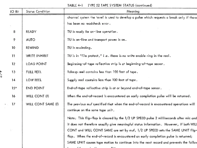
Type 52 Tape System Status ...•.•...
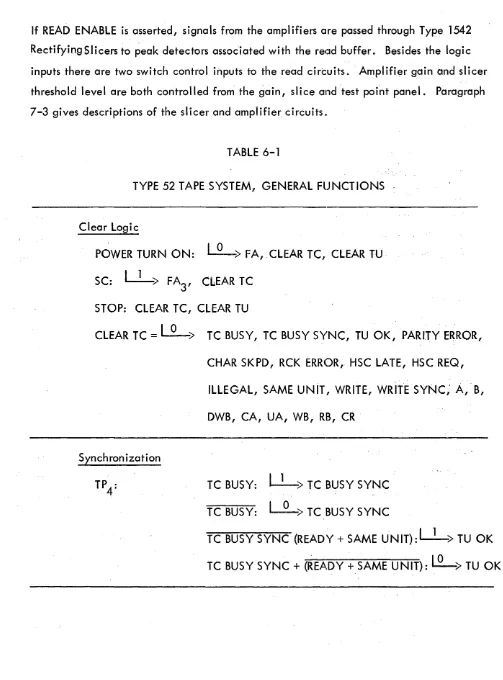
Type 52 System, General Functions ...•..•..•.•..•...
Type 52 System, lOT Command Pulse Operations •.•...
Type 52 Tape Control Logic Levels .•..•...•...
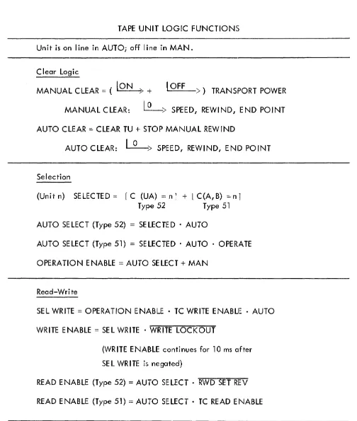
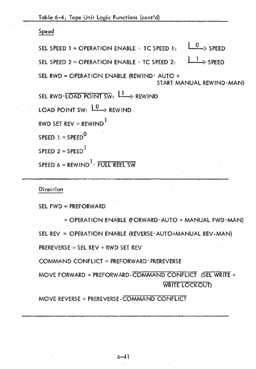
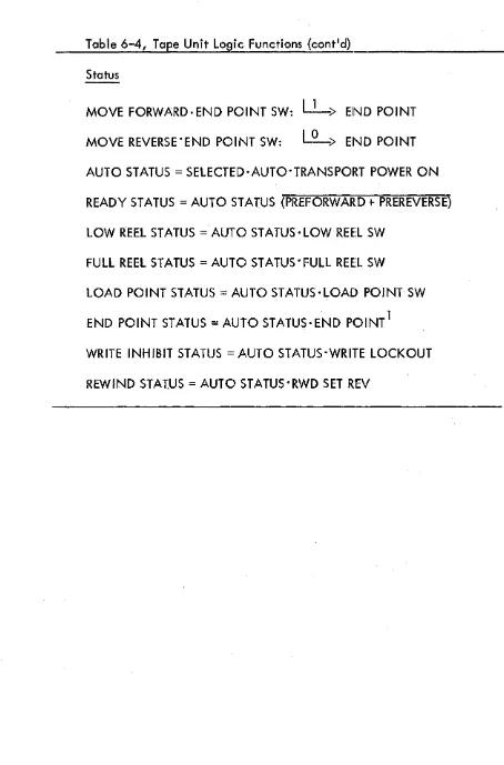
Tape Unit Logic Functions ...•...
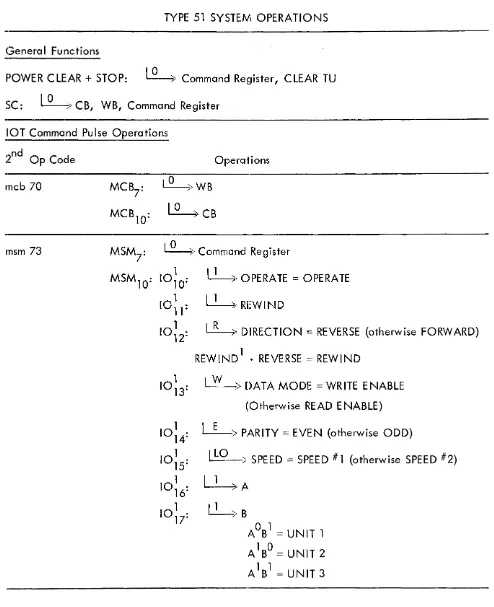
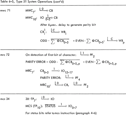
Type 51 System Operations ...••...•...
CHAPTER 1
INTRODUCTION
1-1 PURPOSE AND SCOPE
The purpose of this instruction manual is to aid personnel in the installation, operation and
maintenance of two magnetic tape systems use:d with the DEC Programmed Data Processor-l. This
manual, a supplement to the basic PDP-l Mai'ntenance Manual, describes the Automatic Tape
Control Unit, Type
52;
the Programmed Tape Control Unit, Type51;
and the DEC-designed Local Tape Control, which is mounted in each Type50
Tape Transport Unit. A separate manufacturer's 'manual for the tape transport is furnished with the tape system.Throughout this manual an automatic tape sys1rem comprising a Type
52
Automatic Tape Control and one or more Type50
Tape Units is referred to as a Type52
System 0 A programmed tape sys-tem comprising a Type51
Programmed Tope CClntrol and one or more Type50
Tape Units is refer-red to as a Type51
System.1-2 CHAPTER SUBJECTS
A brief summary of system use and appl ication is presented in Chapter 2, General Description.
Th is chapter a Iso I ists system spec ifi cations and physica I characteri stics.
Chapter 3, Insta Ilation, provides instructions for initia I insta lIation and setup of the system.
Chapter 4, System Function, provides a full ~Jeneral description of all system operations. At
block diagram level, Chapter 4 explains what the system does rather than describing the specific
hardware and connections involved in the various functions. Also included in this chapter are
descriptions of tape format, write and read si!:Jnal flow and all magnetic tape instructions.
Chapter 5, Operating Procedures, explains the use of all controls and indicators on the tape
system control panels, as well as the basic operating procedures for normal functions.
Chapter 6, Tape System Logic, presents a complete and detailed description of the logic in
both tape control units and'of the DEC-designed logic in the tape transport unit. This chapter
Chapter 7, Circuit Description, describes the function, specifications and circuit theory of
all DEC System Modules not described in the basic PDP-1 manual.
Chapter 8, Maintenance, contains information useful in adjustmentv calibration, troubleshoot-~
ing and repair of the tape equipment. This chapter also describes the function and use of the
DEC Tape Un i t Ca lib rato r .
1-3
FIGURESThis manual includes three general classes offigures: logic diagrams, circuit schematics, and
miscellaneous figures such as photographs, f,ow charts, block diagrams qnd layout drawings.
Complete system logic is shown in logic drawings for Chapter 6. This chapter also includes
the flow' charts. Circuit schematics accompany Chapter 7. Block diagrams, photographs and
layout drawings illustrate the other chapters. Ch<;lpters 7 and 8 also include various cable and
wiring diagrams.
All figures are assembled in numerical. order at the back of the manual. References to all figun9s
except circuit schematics are of the form "Figure 5-1" (i .e. the first figure of Chapter 5.)
CHAPTER 2
GENERAL DESCRIPTION
2-1. PURPOSE OF SYSTEM
One of the many PDP-1 options is the magnetic tape system. This system provides computer
in-put-output at a much faster rate than other peripheral devices .. and ' may also be used as high
capacity, slow access storage to augment core memory. Two kinds of tape option are avai lable:
automatic systems and programmed system. This manual describes one system of each kind.
The Type 52 Automatic Tape System transfers blocks of chc;aracters between computer memory
and tape. By using the high speed channels it allows computation to continue while the
trans-fer is in pro'cess. Special features include scaHer read and gather ,write;' automatic bit-by-bit
read-compare with core .memorY' automatic lateral parity error detection while reading and
writing and rapid tape search by skipping a : preserect:ed: number of records. Tape format is
standard IBM with choice of odd or even parity. Each automatic tape control can handle up to
eight tape units. A maximum of three tape controls {for capability of 24 tape units} can be
add-ed to the PDP-1 .
The Type 51 Programmed,Tape System transfers information between computer and tape one
char-acter at a time. All transfer operations including error checking and assembly of charchar-acters
to computer words must be performed by subroutines. Some choice of tape format is allowed
in-cluding standard IBM. the'programmed tape control can handle up to three tape units.
All tape system components are housed in standard DEC equipment frames and run on ordinary
60 cycle, 117 volt current. The control unit of the automatic system contains built-in marginal
checking to facilitate preventive maintenance. No special wiring, subflooring or air
condition-ing is requi red.
2-2 SYSTEM COMPONENTS
Equipment comprising two of the PDP-1 tape s),stems is shown in Figure 2-1. Both systems
in-clude a tape control, the Programmed Tape Cont"rol Type 51, or the Automatic Tape Control Type 52.
Each Type 50 Tape Transport Unit includes the DEC-designed Local Tape Control (read-write
electronics) and two components designed by Potter Instrument Company: the
M906II-l
Tape Transport, and the M3323 Drive ElectronidsUnit~: The type 51 or 52 Tape Control governs thetape unit through the local control. All motion and stotvs signqls between local control and the·
transport pass through the Potter drive electronics. Data signals, however, go directly between
the read-write electronics and the read and write heads.
Both tape systems are governed from the in-out transfer control section of PDP-1 0 For the Type
52 Automatic System ... six jot instructions are added to the computer repertoire 0 These
instruc-tions specify a tape unit, initial and final addresses, and a tape command. The Type 52
Con-trol then selects the specified tape unit and executes the command automatically. This process
is independent of further computer operations, so' the computer may continue with the program 0
All required tape operations are executed by the Type 52 hardware.; Each time the Type 52
Control ;has finished writing a word on tape or reading a word from tape, it gains direct access
to memory: through a high speed channel. Data transfers are made to or from consecutive
mem-ory locations, starting with the in,it'ial address and ending with the final address. Since;the high
speed, channel control includes three channels,- up to three Type 52 Controls (and hence 24 tape
units) may be added to the computer.
The Type 51 ProgrammedTape System, like the Type 52 System, is governed from iot control.
However, all data transfers are made through the in ... out register one character at a time. The
fiveiot instructions added to the computer repertoire select the tape unit and its operating mode
(read or write ... odd or even parity;, etc.) and initiate the individual character transfers. The
write instruction transfers a character from thein-out register to the tape control to be written
on tape; each character read from tape imust be detected by the program and transferred to the
,in-out register by a read i~struction. The program must also assemble the characters into words
and deposit them in memory.
A typical automatic tape system including a Type 52 Tape Control and three tape units is shown
in Figure 2-2. The tape control requires an entire bay and each tape unit, including a tape
transport, is mounted in an additional bay. In a programmed system the tape units also require
2-3
SYSTEM OPERATING SPECIFICATIONSSYSTEM PARAMETERS
Characters
Parity
Lateral
Longitudinal
Transfer rate
Density
Minimum record length (excluding longitudinal parity character)
Type
52
System Type51
SystemLoad point gap
Longitudinal parity character spacing
Inter-record gap
Recording
Errors detected
Type
52
SystemType
51
SystemTRANSPORT PARAMETERS
Tape
Speed
Start time
Start distance
Stop distance
Single unit stop-start interval
Read-wri te heads
Data protection
Detected conditions
2:-3
7 bits: 6 data, 1 parity
Odd or even
Even
15,000
characters/second200
charocters/inch3
characters1 character
0.020"
0.023" (4
character spaces)3/4
11NRZ
Parity, skipped character, read-compare, illegal command, late
HSC
access·
Parity
1.5
mil polyester,2400'
long,1/2"
wide75
ips3
ms0.15"
0010"
10
ms 7 channelLoad point
Full reel
Low reel
End point
Load point and end point detectio,n
Rewind speed
Rewind time
Reel diameter
2-4 PHYSICAL CHARACTERISTICS
CONSTRUCTION
., 10' from 'physical beginning of tape
<
100vof tape on takeup reel
<
100' of tape on supply reel148
from physical end of tape
Photoel~ctric
300 ips
1 3/4 minutes, fu II reel
10 1/2"
All magnetic tape equipment is housed in Standard DEC Blays (all steel construction). Control
panels are aluminum.
MODULES
Standard DEC System Plug-in units, series 1000 and series 40000
POWER EQUIPMENT
Power supplies series 700; power controls series 800.
LOGIC
Solid state. Transistors and crystal diodes operating on static logic levels (0 vdc and -3vdc).
DIMENSIONS
Each DEC bay has the following dimensions:
Height 69 1/2 inches
Width 22 inches
Depth 26 inches
Usually, however, several units are bolted together - the overall length then being 2001
per
unit plus 2" for the end panels. For example, if a Tape Control Type 52 and three tape units
UNIT WEIGHTS
Tape Unit Type 50 (including transport and lo~,ic) 600 pounds
Tape Control Type 51 65 pounds
Tape Control Type 52 500 pounds
Each pair of unused end panels reduces system weight by 90 pounds.
2-5 POWER REQUIREMENTS
LINE VOLTAGE IN'PUT
105 to 125 volts, 60 cycle, single phase
'CURRENT CONSUMPTION
Tape Unit Type 50
Tape Control Type 51
Tape Control Type 52
2-6 EQUIPMENT LIST
7 . 5 amperes average, 740 watts. How-ever, under heavy operating conditionsg
the tape unit may draw 20-ampere peaks"
0.5 ampere, 60 watts
4 amperes (6-ampere peaks), 410 waUs
All PDP-1 tape equipment is housed in Standard DEC Bays. The front of each bay can accom-'
modate up to 12 horizontal 19-'inch mounting panels (DEC Type 1914). Each panel can hold
25S tandard DEC P lug-in logic Modu les. Inside the double doors at the back of each bay is an
inner plenum door supporting the required power suppl ies and power controls 0
A typical automatic tape installation is shown in Figure 2-2. The Type 52 Tape Control (left)
is bay 1. All tape units of a system are designated bay 2 for purposes of module location 0
The tape transport is behind the glass door on ,the front of the tape unit. The transport and the
manual control panel together take up the upper half of the unit. Behind the double doors i.n
the lower half are the logic, the drive electronics, a test panel and a bus socket panel"
a LOGIC PANELS AND POWER EQU IPIMENT - Complete front and back layouts of tape
system bays 1 and 2 are shown in Figures :2-3 and 2-40 The front of bay 1 (Type 52 in~
cludes an indicator panel and seven mounting panels of logic. In general each mounting
panel contains a complete subsection of logic and is shown in a single logic drawing in
Chapter 6. The figure number is at the lower left of each panel. On the back of bay 1
are a power control, the logic power supplies and a variable power supply for marginal
checking.
The upper half of bay 2 (tape unit) contains the tape transport and the manual control panel.
The components listed in the layout drawing (Figure 2-4) are also shown in Figure 2-5, a
photograph of the tape unit with the double doors open. Below the transport is the drive
electronics: test points and fuses on the left, plug-in modules on the right. The DEC tape
unit equipment, below the drive electronics, includes the gain, slice and test ponit panel,
the logic for local tape control and the bus socket and taper pin panel for cable connections
between tape control and tape unit. The unit shown in Figure 2-5 is unit 1 ofaprogrammed
tape system. Below the bus socket panel is the logic for the Programmed Tape Control Type
51. In all units of a Type 52 System and in units 2 and 3 of a Type 51 System, this logic is
replaced by a blank pane I.
The back of the tape unit (Figure 2-4) includes an isolating transformer, a power control
and a power supply for the Type 50 Logic. However, in unit 1 of the Type 51 System,an
ad,-ditional power control and power supply for the Type 51 Logic are mounted at the top of thE~
plenum door.
The following table I ists the mounting panel and power equipment requirements for the
three tape system components described in this manual.
Tape Transport Unit Type 50 (Figure 2-4)
Space requirement
Logic
Power equipment
1 bay
1 mounting panel (2G)
1 power supply 728
1 power control 822 (811 B)
1 isolation transformer
Programmed Tape Control Type 51 (Figure 2-4)
Logic
Power equipment
1 mounting panel (2H)
1 power supply 728
~utomatic Taee Control Type 52 (Fig~Jre 2-3)
Space requirement
Logic
Power equipment
1 bay
7 mounting panels (lA to 1 H)
3 power suppl ies 728
1 variable power supply 734
1 power control 811
b MODULE LIST - The following list includes all plug-in modules required by local tape
control in the Type 50, Programmed Tape C:ontroLlype.5:1 andAutomatic Tape Control Type
520 Circuits indicated by an asterisk (*) Clre described in Chapter 7 of this manual 0 All
other circuits are described in Chapter 10 of the basic PDP-1 manual.
Local Tape Control
~
Differential Amplifier 1536'k or 1549*'
RectifyingSlicer 1542*'
Indicator Driver 1669
Inverter 4105
Inverter 4106R
Diode 4112R
Diode 4113
Delay 4301 NRZWriter 4514* Quantity
4
3 5 1 3 2 1 4Pro,grammed T~pe Control.~y'pe51 and Automatic Tape Control Type 52
-Numbers in parentheses indicate modules that must be added to PDP-l
iot control to govern the tape system 0
Quantity Type
Delay 1304
Type 51 Type 52
1
,Peak Detector and SI icer 1539*
Indi cator Driver 1669
Bus Driver 1685
2-7
4
4Quantity
Type Type 51 ' Type 52
Inverter 4105 2 (1) 14
Inverter 4106 2
Inverter 4106R 9
Diode 4111 4
. Diode 4112 2
Diode 4112R
Diode 4113 2 13
Diode 4113R 2 3
Capacitor-Diode 4126 6
Capac i tor-Diode 4127 2 5
Capac i tor-Diode 4127R 4
Capacitor-Diode 4128 2 14
Binary-to-,Octal Decoder 415.l*
Dual Flip-Flop 4202* 9
Dual Flip-Flop 4209 2
Quadruple Flip-Flop 4213 5
Quadruple Flip-Flop 4214 4 11
4-Bit Counter 4215* 2 2
Delay 4301 2 17
Integrating Delay 4303* 3
Clock 4401
Clock 4407*
CHAPTER 3
INSTALLATI·ON
3-1 SITE SELECT ION
Before installing a magnetic tape system! select a suitable location near the PDP-1 computer.
The Tape Control Type 52 must be installed within 25feetof the computero Furthermore! the
tape units must be within 25 feet of the tape control 0 In the programmed system the Type 51
Tape Control is mounted in tape unit 1 so the entire system must be within 25 feet of the
com-puter.
All system equipment frames are 69 1/2" high. The floor area occupied by the system depends
upon the number of tape units that are included (equipment dimensions are given in paragraph
2-4) 0 Usually the equipment frames are bolted together in groups. At least 3 feet of clearance
should be allowed on all sides of the equipment for access during maintenance.
A level Hoor is required because the equipment' frames are mounted on casters. The floor shou Id
be capable of supporting 150 psf.
The system is designed to operate efficiently from 500 to 100°F. The plug-in modules are
cool-ed by blowing air out the front of the bays. Intake fans are factory-installcool-ed in the floor of all
DEC bays, and in the top of each tape unit bClY as well 0 No additional cooling equipment is
required 0
All units run on ordinary 115 volt, 60 cycle current. Since each bay has its own ac line" a
separate outlet must be provided for every unit. Tape units should each be. connected to a 20
ampere line. A 10 ampere line is sufficient for the Type 52 Tape Control. All cables are
equipped with Miller Electric Type 034-2 Connectors.
3-2 INSTALLATION
The bays containing the tape control and the tape units are usually bolted together into one or
two large equipment frames. However! the drive electronics and the isolation transformer for
each tape unit are packed separately and must be installed before the system is ready for use.
All cabling within a single equipment frame is installed at the factory.
All
cables necessaryto connect the different frames are packed in a single separate container. Thus a tape system
including one Type 52 Control and three tape units would be shipped as a single large
equip-ment frame and seven additional containers: three contain"drive electronics units,· three
·con-tain isolation transformers,ond·Qne .. con·con-tains the necessary cables.,
a UNPACK I NG - Each equipment frame is shipped on a skid. The frame is wrapped in
plastic, a wooden cover is placed on the top, and the entire package is held on the skid
with metal straps. The tape unit subassemblies and cables are shipped separately in
ordin-ary packing containers.
(l) Carefully remove the metal straps, wooden cover and plastic from the equipment
frame. Remove the frame from the skid and place as desired near the PDP-l"
(2) The plenum doors at the rear of the bays have spring catches. To reinforce these
doors during shipment two screws are used to hold each door shut. Remove these screws
and store them in the plastic loops provided 0
(3) Remove any packing material, shipping blocks, etc., from the inside of the frame.
(4) The plug-in modules are taped into the logic panels to prevent damage in shipment.
Remove the tape 0
(5) Unpack the cables, transformers .. and drive electronics units 0
NOTE: If the user plans to reship the equipment (or move it more than a short distance) in the near future, special packing materials should be saved for reuse. The containers for drive electronics units and transformers, in particular, are designed especially to accom-modate the equipment and are the safest means of packing it for re-shipment.
b INSTALLATION OF SUBASSEMBLIES - The user must install a.drive electronics unit
and an isolation transformer in each tape unit. Mount the drive electronics just below the
tape transport wi th the fuses at the left end of the un it (see Fi gure 2-4). The mounti ng bolts
are already in place at the sides of the bay front, behind the double doors. Correct
mount-ing of the unit is shown in Figure 2-4 of the Potter Handbook 0
Two cables connect the drive electronics to the rest of the tape unit. The cable from the
into the smaller receptacle at the back 'of .the drive electronics u The cable from the lope
, transport. is, coi led and taped around th~, transport motors . Remove the tape and p~ug 'j~;s
cable into the, larger receptacle at the back of the dj~veelectronicso
The isolation transformer must be mounted on the second panel from the bottom 'on the ~n
side of the plenum door at the rear of the bay {see F~gure 2-4). The mounit"lng 'boh"s and
connecting cables for the transformer are (llready ',n place. Each cable is marked by c r:dm,'"
bered tag. On the front of the transformer are two sets of terminals covered wF.th p~.:i5Tl:C
plates. On the plastic are strips of tape bearing conesponding terminal numbers" CO[H"lect
the cables to the matching 'transformer term~nals.
c BUS CONNECTIONS - At the bottom of each tape unit is a bus socket and taper' pIn
panel (Figure 3-1). The socke't in the upper right provides connection to the manual cop·"
trol panel at the top of the unit. The other two sockets are for the tape con.trol
bus
(IC bus). ;AII,tap~ units are connected to a single bus from the tape control. The
Te
bus 'enteJS eachtape unit at the left of the socket pane! and leaves at the lower right. Connections betwee'1
the two sockets are made through the taper pins in the center of the panel" T~ere a,~e tt-ree
taper pin' blocks17 each containing three horizont'O! rows of pins. In allrhree bl.ock5J con~
nections from the in·-bus are made to the center row! whi!e connections to the but~bus are
made from the bottom row. Connections to the Type 50 Logic and to the socket fOf the con~
trol panel connector are made from the top row.
All cables within a single equipment frame are insta!led at the factory. Howeve~, bus co~~
nections between the tape system and the computer 7 and between separate equ!pment frames
! . '
within the system, must be made at the site.
Bus connections for the Type 52 Tape System are shown ;n Figure 3-2. A panel conta~nhjg
four bus sockets is located at the bottom of the Type 52 Control. Three cables conneCT the
tape system to the in-out transfer control section of the PDP-I ... The in-out plugs at the computeu
are labelled to correspond to the bus sockets at the tape control ~ J52-1 K -2 and -3. The
Te
bus socket v J52-4, is equ iva lent to J50-4A and J50-4B in a I! tape units. ~f the systemis divided between two equipment frames, J50-4B in the !as"t unit of the first frame must be
The bus connections for the Type 51 Tape System are shown in Figure 3-3. Since the
pro-grammed Tape ControlType 51 is mounted in tape unit 1,and all three units are bol ted into a
single frame, only one bus need be installed. This connects the computer to J51-4 at the
left of the unit 1 socket panel. Connections to the Type 51 Control are made directly from
J51-4. Connections between the Type 51 and the rest of the tape system are then made
through the taper pins. Note, however, that the bus connections in tape units' 2 and 3 are
just the opposite of those in the units of the Type 52 System. The bus connections are
re-versed in order that all tape units except unit 1 of the Type 51 System will have the same
taper pin wiring. The unit that contains the Type 51 Logic must provide voltage to the unit
calibrator through the out-·bus. Reversing the bus connections prevents the mixing of logic
voltages between two adjacent units.
3-3 INSPECTION AND CHECKOUT
The tape system is thoroughly tested and checked before it leaves the factory. However, it
should be inspected and checked again after installation to make sure that no damage has occur-·
red during shipment.
a INSPECTION - After the tape equipment has been unpacked and installed, the system
should be inspected visually. Check the following:
(1) Havea driveielectronicsunit and an isolation transformer been installed in every
tape unit?
(2) Have all bus connections between computer and tape system been made properly?
(3) Have all shipping blocks, packing materials, tape, etc. been removed? A coiled
ac power I ine is taped to the fan at the bottom of each bay. Remove the tape but do
not plug in the power lines.
(4) Are all plug-in units inserted firmly in position?
(5) Are there any loose nuts or bolts?
(6) Are there any loose or broken wires?
b PREOPERATIONAL CHECKOUT - Before using the tape system make sure that the entire
procedure makes use of the following swi tches:
The POWER switch and indicator locat'ed at the lower right of the Type 52 Indicator
Panel)
The TRANSPORT POWER switch and indicator located at the left end of the tape unit
manual control panel;
The circuit breakers and LOCAL/REM(JTE switch on each Type 811 and 822 (811 B)
power Control,.
All switches and indicators in the tape system are described in detai I in paragraphs 5-2 and
5-3.
The following checkout procedure is complete for both the Type52
and Type51
Tape SystemsQ For either system merely ignore those steps that refer only to the other. All stepsthat refer to the tape unit should be performed on all tape units.
(1) Make sure computer power is off 0
(2) Turn OFF the TRANSPORT POWER switch on the manual control panel. Turn off
(down) the Type 52 POWER,switch.
(3) Load a tape into the tape unit 0 Complete tape loading procedure is described in
paragraph 5~4o
(4) Switch the 811 and 822 power controls to REMOTE 0
(5) Plug in the ac lines and make sure: all 811 and 822 circuit breakers are closed. All
units should remain off.
(6) Switch the 822 power control to LOCAL. This applies po~er to the Type 50 Logic.
(7) Set TRANSPORT POWER to REMCITE. Nothing should happen.
(8) Push TRANSPORT POWER to the momentary contact ON position. The transport
should go on, lighting the associated iindicator. When the switch is returned to
RE-MOTEi' power remains on.
(9) Switch the 882 power control to REMOTE q All tape unit power including the
trans-port goes off.
(10) Turn on (up) the Type 52 POWER switch 0
(11) Switch the 811 power control into LOCAL. With Type 52 this turns on the power
indicator and applies power to the entire tape system. With.the Type 51, both the 811
and the unit 1 822 power controls must be switched to LOCAL. This turns on only the
Type 51 Logic and unit 1. (To turn on the entire system, switch all power controls to
LOCAL.)
(12) Switch the 811 power control to REMOTE. With the Type 52, the entire tape
system should go off. With.theType 51 all power controls must be returned to REMOTE
to turn off the entire system.
(13) Turn on the computer. The entire tape system should go on with the computer.
(14) Tu~n off the computer. The entire tape system should go off.
CHAPTER 4
SYSTEM FUNCTION
4-1 LOG~CAL ORGANIZATION
The logical configuration of the PDP-1 Type 52 Automatic Magnetic Tape System is shown in
Figure 4-1. The Tape Control Type 52 functions as an automatic buffer between the computer
clnd the tape un its. Program iot instructions govern the entire tape system by providing
ad-dresses and commands to the tape control. The tape control then goes into automatic
opera-Hon, regulating both its own operations and th()se of the addressed tape un it. All data
trans-fers between tape system and computer are made directly to memory through a high speed
channel.
To place. the tape system in operation the program must provide three types of information:
1.. It must select a tape unit by providing a unit address.
2.
It must specify the quantity of data to be processed by providing a pair of memoryad-dresses. These addresses define a rangE~ of memory locations for retrieva
I
or storage ofdata through a high speed channel.
30 It must te
II
the system what to do with the data by providing a tape command.The program performs the first two functions through the address logic, the third through the
command logic ..
The address logic conta ins three registers and an equa
I
ity net. The program provides thesethree registers with tape un it, in itia I and fino I addresses. For each tape operation the tape
control selects a tape unit according to the unit address (UA). The first HSC access to memory
is made according to the initial address. Subs€lquently, the initial address becomes the
cur-rent address (CA) c The tape control keeps count of data transfers by incrementing th is current
clddress by 1 on each HSC access. When the clJrrent address becomes equal to the final address
{FA),the equality net indicates that the operation is complete. This equal address condition
produces a sequence break in the computer 0 If the program then resets the initial and final
clddresses before termination takes place, the operation continues.
Besides providing addresses to the tape control,the program must also provide a tape command
to the command register (CR). The command is decoded to govern the operation of both the
tape control and the selected tape unit. The control portion of the Type 52 contains two parts:
in-out control and format control. Basically, in-out control governs the transfer of information
between computer and tape control, wh i Ie format control governs transfers between tape control
and tape unit. In-out control governs program initiation of all tape operations, transfers ,of
data through a high speed channe I and' requesting of sequence breaks. All status leve Is for
both tape control and tape un it are; a Iso provided to the computer by in-out control.
Format control incl udes logic for the sequences of operations that produce the correct tape
for-mat in writing and that respond properly to the same forfor-mat in reading. Forfor-mat control a Iso'
generates high spee,d channel requests whenever a full computer word has been read or written;
it provides timing for the termination of a tape operation inorder to produce the correct record'
gap; if positions the'tapeproperly""with"resp'ectto the read and write heads.
Data is transferred between computer memory and tape through a set of three data transfer'
registers. All transfers between computer and tape system are full-word transfers between the
memory buffer and the 18-bit data word buffer (DWB). In writing, format control divides the
word in DWB into three characters which are made available to the tape through the
single-character write buffer (WB). In reading, format control assembles three consecutive single-characters
from the single-character read buffer (RB) into a full word in DWB.
In the programmed tape system, the Type 52 Control is replaced by a Type 51 and no use is made
of high speed channe Is or sequence break system. All' command information and data are
trans-ferred through the in-out register and most control and address functions must be provided by
the computer. The Type 51 Control includes only a pair of single-character buffers for data
transfer and a command register which includes bits for tape unit selection. All data
trans-fers are single-character transtrans-fers, made completely under program control. In writing, the
program must transfer each character to the character buffer (CB); it is then made avai lable to
the tape through the write buffer (WB). In reading, the character buffer doubles as a read
buffer, and the program must transfer each character to the in-out register. The command
reg-ister spec ifies the tape un it operating mode but governs no functions in the tape control except
4-2 TAPE FORMAT
PDP-l magnetic tape un its use 1/2" wide tape conta"ining 7 information channels. The tape
format produced by the Type 52 Automatic TapE~ Co~trol is shown in Figure
4-20
With the Type51 Programmed rape Control the computer may provide the necessary timing to duplicate thus
for-mat or may write the tape in some other forfor-mat if desired.
The left part of Figure 4-2 shows the tape in re lotion to the read and write heads. The tape
moves by the heads vertically - forward direction be ing downward. The tape is composed of
CI mylar base coated on one side with an iron oxide composition. The oxide or dull slide of the
tape faces the heads; with the left edge toward the transport drive plate 0 The recording rate
of 15g000 characters/second means that one ch'Jracter is w.ritt~n e~ery 66.67 microseconds.
Since the tape moves at 75 ips, there are 200 characters/inch,and the characters are spaced
0.005 inches apart.
The method of recording used is nonreturn-to-zI3ro (NRZ). Altho:l:Jgh the tape has two basic
states of remanent magnetization, the remanent magnetic state of the tape at a given bit
posi-tion does not determ ine the va I ue of that bit. .A logica I 1 is represented by a change from one
state of magneHzation to the otheri' in either direction. A logical 0 is represented byaconstant
state of magnetization. Thus, writing a character containing all Os is equivalent to producing
blank tape 0 Each time a character is transferred into the write buffer, the NRZ writers produce
an equ~va lent character on the tape 0 Because I)f the NRZ type of recording however!7 a
trans-~er unto the buffer is not a norma I 1 transfer. Instead, whenever a 1 is to
be
written in a givent,ape channelgthe corresponding bit of the buffer is complemented, producing a change in tape
magnetization.
The structure and spac ing of the individua I tapE: characters are shown at the right in Figure 4-2.
Each l8-bit computer word is divided into three: 6-bit characters in DWB 0 The write buffer,
however g conta ins seven fl ip-flops corresponding to the seven tape channe Is 0 A parity bit is transferred i'nto the buffer with each 6-bit data character I producing a tape character of six
data bits and a lateral parity bit. Channell contains the least significant data bit; channel
6, the most significant 0 The parity of the char<lcter may be either odd or even, as specified
by the program 0
In reading the tape [I only 1 s are detected. If odd parity is used," there must
be
a 1 in at leastone channel'of every'character so thafall:characterswj] rbe "detected .• However, if six 0 data bits
are written with even parity, a character conta in ing a II Os is produced. Th is is equiva lent to
a character space and is interpreted by the system as a missing character error. After the first
1 bit of a character is detected,the tape control waits 25 microseconds for the read buffer to
receive all the bits in the character. This procedure allows a tape skew of up to 0.0018"
with-out loss of information.
The sma lIest un it of information that can be written on the tape is a record. Since each word
is divided into three characters, a record contains 3n data characters, where n is the number
of words provided by the computer for a given write operation. After the last data character
is written, the tape control writes 0.020" of blank tape (270 microseconds at 75 ips), and then
clears the write buffer to produce an end-of-record character (EaR). A complete record
there-fore contains 3n+ 1 characters, that is, 3n data characters and the EaR character 0 Since the
write buffer fl ip-flops a I ways begin a record in the 0 state, return ing the buffer to its in itio I
state at the end of the record produces even longitudinal parity in all tape channels.
The sma Ilest un it of information that can be read by the tape control is a Iso an entire record.
Th is does not mean, however, that the entire record must be deposited in computer memory.
In a r~ad operation, the program specifies in itia I ,!nd fina I addresses for transfer of information
to memory. If, when the addresses become equal, they are reset within 100 microseconds, the
operation continues. If the addresses remain equal for longer than the allowed time, all high
speed channe I transfers to memory cease, but the tape control continues reading unti I the end
of record is reached. If the address range specified by the program is greater than the number
of words in the record ,the tape stops at the end of the record even though the addresses have
not become equa I •
In all normal tape operations, therefore, the tape always stops so that both the read head and
the write head are with in the record gap. The distance that the EaR character moves beyond
,the read head, in combination with the delay before writing is allowed, always produces at
least 3/4" of blank tape between records. Since only
1s
are written on the tape (the failure to detect a 1 during the reading of a character is interpreted as a 0) the absence of writesig-na Is during a write operation erases the tape, i.e. produces blank tape. The actua I position
of the heads within the gap depends upon the type of operation just completed. The EaR
I
generation of inter-record trash, which can be produced
by
failing to erase the entire record gap when writing on a previopsly
recorded tape.Since the spacing between the read and write heads is 003011
, every character passes the read
head 4 mi I
i
iseconds after it is written 0 Th us in a write operation the characters are read inorder to check for parity or missing character errorsibut no transfers beyond the read buffer
occur.
Besides detecting changes in magnetization through the read head,the tape unit also includes a
photoe lectric system for sensing beginn ing and end of tape and a mechan ica I system for
detect-ing low tape supply. The low reel condition (IE~ss than 100 feet of tape on the supply reel) is
prov ided to the tape control as a status condit ion but is not used with in the tape un it ~ In the
rE~wind operation, the full reel condition (less than 100 feet of tape on the takeup reel) returns
the tape un it to norma I speed for the rema inder of the rewind and the tape fina I i y ha Its at load
point. The load point anq end point of the tapE! are marked by reflective strips mounted on the
side of the tape away from the heads. These strips are detected by photodiodes which sense
I ight reflected from them. In writing on a newl y mounted or rewound tape v a gap of 611 is left
from the !oad point before writing can begin. If the tape should run to the end point in any
operation the tape unit stops automatically.
4·-3 TAPE WRiTE AND READ SIGNAL FLOW
Fiigure 4-3 is a block diagram of the tape system write and read paths for a single channel o · The
write path begins at the write buffer in the tape control and ends at the tape, wh lie the read
pClth begins at the tape and ends at the tape control read buffero Most of the equipment shown
in the figure is located physically in the read-write electronics of the tape unit 0
In the write path, both outputs of a WB fl ip-flop are connected to an NR Z writer whose three
outputs are in turn connected to the two ends and centertap of a write head inductor 0 The
NRZ writer contains a pair of semiconductor switches 0 If the write enable level IS not asserted,
both switches are off and no current flows in the inductor. However, if write enable is asserted,
one (and only one) switch must be on because the two switches are controlled by complementary
outputs of a WB flip-flop. If the upper switch is closed,? current flows through the upper coil
in the direction shown by the arrow. If the low(~r switch closesu current flows through the
low-er coil 0
The tape control writes information on the tape by complementing the WB bit. So long as a
given WB bit remains in the same state, the corresponding writer switch remains closed,and
current sti II flows through the same ha I f of the write head coi I. Th is is equiva lent to writing
as on the tape every 66.7 microseconds. Whenever a 1 is to be written on the tape, the WB
bit is complemented; th is reverses the states of the two writer switches, causing current to flow
in the other ha I f of the coil. Th is, in turn, changes the direction of magnetization in the tape
channel. Current flow through the two halves of the coil for writing a typical tape message is
shown by the graphs above and below the current lines. A similar graph represents the direction
of tape magnetization for the same message as shown at the right.
A tape passes the read head 4 mi" iseconds after pass ing the write head. So long as the
direc-tion of tape magnetizadirec-tion remains the same, no current flows in the read head coil. However,
when the read head encounters a change in the direction of magnetization, current flows throug,h
the coil. Each change causes current flow in the opposite direction from the preceding change.
Typical current flow for two consecutive tape 1s is shown by the waveforms above the
connect-ing lines from the coil to the differential amplifier.
The differential amplifier provides considerable amplification for difference signals but only
fractiona I ampl ification for common mode signa Is. Ampl ifier waveforms are shown to the left.
The ampl ifier a Iso inc! udes a balance potentiometer to assure that the output signa Is are the
same ampl itude regardless of polarity.
The output of the differentia I ampl ifier is appl ied to a rectifying sl icer. No s I i cer output can
be generated unless the read enable level is asserted. This prevents the sending of read signals
to the tape control when tape is in motion but is not be ing read as , for example, in the rewind
operation. The rectifying slicer generates a negative output pulse for an input pulse of either
polarity from the differentia I ampl ifier. However, no sl icer output is generated unless the
in-put exceeds a threshold level> Thus a low level noise inin-put cannot generate an outin-put pulse.
The rectifying slicer output feeds a peak detector and slicer in the tape control. The pu~se
produced through the read path from the read head is long compared to the duration of most
logic leve Is with in the tape control. Therefore, for the time during wh ich the input pulse
exceeds a preset threshold level, the slicer portion of the peak detector and slicer produces a
logic leve I output. Further, the peak detector produces a logic pulse output at the peak of the
4-4 TYPE 52 TAPE INSTRUCTIONS
/
With the installation of a Type 52 Automatic Tape System, eight in-out transfer instructions are
added to the PDP-1 repertoire. Each of these instructions is executed in a single computer
memory cyc Ie of 5 microseconds. In order to place the tape system in operation, the program
rrlust execute the two initiating instructions. These provide the necessary addresses and tape
commands. The tape system then executes the command automatically. When the
address-. equal condition occurs during a tape operation, the program may provide new initial and final
addresses through the two reset instructions without stopping the tape operation in process. The
automatic tape instructions also include a pair ()f examine instructions (through which the
pro-gram may check the condition of the tape system) and a pair of maintenance instructions. The
entire set of eight instructions uses the iot primclry operation code and six of the secondary:
oper-ation codes (both maintenance instructions use the same second code as one of the reset
instruc-tiions). Furthermore, one of the initiating instructions has a third 4-bit operation code. This
third code is the tape command which is execut,ed by the tape control.
In all magnetic tape instructions, bits 6 and 7 of the instruction word (denoted by lab' in the
instruction code) select the tape control. The three tape controls are addressed at 00, 01 and
10. If there is only one tape control these bits are ignored. In the following
I
ist theinstruc-tiion codes are given in octal with capital letters representing variable octal digits.; Whenever
binary digits are necessary, they are given as h and Os in parentheses or are represented by
lower case letters. For convenience, the tape ,:ontrol is often referred to as the 'lCu while the
tclpe unit is referred to as the TU. In some instructions, reference is made to various status bits.
These correspond to the tape status conditions and are described under the instruction mes. Each
status bit number corresponds to its'position in the in-out register when tape status is examined
by meso
Initiating Instructions:
Magnetic Tape Unit and Final Address
•..•. muf InstrucHon Code 72abxC76
The C(AC 15-17) replace C(UA); C(l02_17) replace C(FA). The unit address transferred to
UA selects that TU whose unit selector is set to the same address. If the program is about
to initiate a read or write command, the memory address transferred to FA must be 1
greater than the des ired fina I address to wh ich high speed channe I access is to be made during
execution of the command 0 However,. if the program is about to initiate a space command, the'
number transferred to FA must be 1 less than the total number of records to be spaced over.
If the selected TC is not busy, muf is properly executed and the computer skips the next
instruc-tion iii sequence e If TC is busy I' muf is performed as a nop and the computer goes on to the next
instruction in sequence. In eit~er event fJ C(lO) and C(AC) remain unchanged 0
Bits 5, 8 and 9 of the instruction are ignored 0 Bits 10 and 11 (octal digit C): adjust the states, of
the continue fl ip-flops in order to select one of three possible end-of-record actions 0 When.~he
end of a record is reached, the tape control clears the busyfl ip-flop (status bit 3) and returns; ,a
completion pulse to the computer 0 If the sequence break system is on, the TC requests a br~~k.
The three end-of-record actions are as follows:
(1) Normal Completion and Stop" C=Oo Upon reaching the end-of-record, the
tap~:
stops with the head at the appropriate distance past the EOR character. The tape
co'n-trol waits 10 milliseconds to allow the pinch rollers to settle down and then retu~ns the
completion pulse 0
(2) Early Completion and Stop, C=l. Upon reaching theend-of-record, TC
retu~n~"
the completion pulse immediatelyo Thus the programmer can use the same TC to initiate
a tape command on a different TU while the previously selected TU is stopping .. This
saves 10m i II iseconds of program time 0
(3) Early Completion and Continue, C=30 Upon reaching theend-of~recordi TC
re-turns the completion pulse immediately,and the previously selected TU continues in.
operation. Duri'ng
a
2 millisecond interval following. the completion pulse, theprQ:-gram must provide new in itiating instructions 0 Iii this manner many records can
Qe,
pro-cessed wifhoufstbpping the,tape. Ifnew instructions ate not given within the allotted
time, TC repeats the previous command with Early Completion and Stop, producing'
the following results:
(a) If the previous command was Write fI the tape control writes a complete record
gap and then stops with the heads at the appropriate distance in a second gap.