United States Patent
[\9]Rubinson et al.
[54] DISK FORMAT FOR SECONDARY STORAGE SYSTEM
[75) Inventors: Barry L. Rubinson; Mark A. Parenti; Richard F. Lary; Edward A. Gardner, all of Colorado Springs, Colo. [73) Assignee: Digital Equipment Corporation,
Maynard, Mass. [21] A ppl. No.: 308,771 [22) Filed: Oct. 5, 1981
[51) Int. CI.3 ... G06F 11/10 [52) U.S. CI. ... 371/10; 360/53; 364/200; 371/13 [58) Field of Search ... 371/10, 13, 38; 360/47, 360/53; 364/200, 900
[56) References Cited U.S. PATENT DOCUMENTS
Re.31,069 10/1982 Chang et a\. ... 360/53 3,059,266 10/1962 Cleveland ... 371/13 4,037,091 7/1977 Beuscher ... 371/13 4,152,695 5/1979 Democrate et a\. ... 371/10 4,214,280 7/1980 Halfhill et a\. ... 360/53 Primary Examiner-Charles E. Atkinson
Attorney, Agent, or Firm-Cesari and McKenna
[57) ABSTRACT
In a disk mass storage facility for data processing sys-tems, a disk fo.rmat which improves handling of
defec-CALCULA TE [DC
[\\ ] [45]
4,434,487
Feb. 28, 1984
tive segments of medium and reduces access time. The format has three layers. A first, physical layer comprises the bytes, sectors and collections of sectors, as well as error detection and correction codes. A second, logical layer is used to address the physical layer and to collect together sectors to form a mUltiplicity of separately addressable spaces, with each space having a distinct functional utility. At a third, functional layer the use of data fields in each space is specified. This layer governs the handling of bad blocks if required, and the use of certain format information. Handling of bad blocks is controlled by a hierarchically layered process. A por-tion of each disc, distributed across the medium, is re-served as spare sectors to replace defective sectors. After a bad sector is replaced, future attempts to access the bad sector are redirected (i.e., revectored) to the replacement sector. For the simplest revectoring, the bad block is replaced by a replacement block in a known location. If that cannot be done, multiple copies of the replacement block's header are stored in the bad block's data field and the copies are compared to find the replacement address. If the comparison fails, or the header cannot be read, a back-up table is available to match the available replacement addresses with the original address which was replaced. A special code is used to identify blocks wherein the medium is good but the contents of the block are logically corrupted.
18 Claims, 36 Drawing Figures
360 362
364
378
u.s.
Patent
Feb. 28, 1984
Sheet 1 of 27
4,434,487
2
A; '
,
DISK
10
HOST
CONTROLLER
DRIVE
. /
4
L)
l,
3
Fig. fA
5
7
C
12A
14
12
C
Lc CYLS \
C+Lc
~H
LBN's
I~SP
LBN's
I---'
~
L-
r-HOST
APPLICATION
AREA
(LBN's)
VISIBLE
TO
I
RBN's
HOST
-,
APPLICATIONS
REVECTOR
CONTROL
TABLES
"-(LBN's)
)
VISIBLE TO HOST
I
C+Lc+Xc
C+Lc+X
XC CYLS
Dc cn S
FORMAT
DIAGNOSTIC
AREA
CYLINDERS
(XBN's)
(DBN's)
\
(
128
16
18
r
OPERATING SYSTEM
i
~
VISIBLE TO CONTROLLER
~
Fig. Ie
ER
c+Oc
c
.
VJ
.
""C
~ f""t-~::s
f""t-61
?"
N
$10
-10 00
~
en
::r
o
o
....
N
~
N
- l
~
...
~
w
~
...
~
00
U.S. Patent
Feb. 28, 1984
Sheet 3 of 27
4,434,487
BOOLEAN PROCEDURE MULTI-REAO(TARGET.COPY.SIZE.N.DATA.BLK);
INTEGER TARGET.COPY.SIZE.N;
INTEGER ARRAY DATA.BLK
(0:143);
INTEGER BLOCK.NEXT,I;
BEGIN
BLOCK ; = TARGET;
NEXT :=
0;
LOOP:
READCOMPARE(BLOCK)DATA~BLK;IF ERROR THEN
BEGIN
END;
NEXT := NEXT
+1;
IF NEXT =
N
THEN GOTO EXIT;
BLOCK := BLOCK
+COPY.SIZE;
GOTO LOOP;
EXIT:
MULTI-READ:= NEXT
<>
N;
EXIT ;
END;
u.s.
Patent
Feb. 28,
1984
Sheet 4 of 27
4,434,487
BOOLEAN PROCEDURE
MULTI-WRITE(TARGET,COPY~SIZE.N.DATA.BLK);INTEGER
NEXT.ERR~COUNT,BLOCK;BEGIN
BLOCK
:=TARGET;
NEXT
:= ERR~COUNT.=
• rio. lJ ,LOOP: WRITECOMPARE(BLOCKlDATA.BLK;
IF UNRECOVERABLE ERROR THEN BEGIN
END;
ERR.COUNT
:= ERR~COUNT +1;
WRITE.FORCE.ERROR(BLOCKl DATA.BLOCK;
NEXT
:=NEXT
+1;
IF NEXT
=N THEN GOTO DONE;
BLOCK
:=
BLOCK
+COPY.SIZE;
GOTO LOOP;
DONE: MUL TI-WR HE :
=
ERR.COUNT
<
N;
END;
U.S. Patent
Feb. 28, 1984
Sheet 5 of 27
4,434,487
FAILURE IN
MIDDLE OF
BBR
Fig.4A
110
RECEIVE NOTIFICATION OF
BAD BLOCK DETECTED
SUPPLY INFORMATION
SUPPLY
INFORMATION
114
LOCK OUT ACCESS
TO BAD BLOCK.
AND UPDATE! WRITE
ACCESS OF RCT
CLEAR BUFFER
&
WRITE IN
BAD BLOCK CONTENTS
u.s.
Patent
Feb. 28, 1984
Sheet 6 of 27
128
SIGNALS
FLAG
REPORT TO
ERROR LOG
130
WRITE DATA FROM
STEP 120
YES
RECORD BAD BLOCK'S
LBN
124
4,434,487
B ...
--.,.----=S~E
C:;".;T..::.O:..:..,R ...::0_.-.J
NOT SUCCESSFULLY READ
SECTOR
0
NOT SL-UC--C-::-E S":::S'::-":F::"':'UL"::::L:':"Y
~W-R-IT--T-E
N...t E
At---~
W/R TEST PATTERNS
132
BLOCK
TO CONFIRM BLOCK BAD
BAD
BLOCK MAY BE
GOOD
NOT
F
BAD
WRITE SAVED DATA TO
BAD BLOCK
134
u.s.
Patent
Feb. 28, 1984
Sheet 7 of 27
4,434,487
138
RE
T S
SCAN RCT
136
POR
CAN SCAN
AND DETERMINE
F AlLURE TO
'---1
ERROR LOG FAILE RBN TO USE
&
OLD RBN
IF THERE WAS ONE
142
140
REC. NEW RBN
REPORT TO ERROR
WHETHER REPL. BEFORE
LOG REPL. FAILED
OLD RBN; PHASE 2
146
REPORT TO ERROR
LOG BLOCK CAN'T
BE READ
152
REPLACE COMMAND
FAILED
158
REPORT TO
ERROR LOG
UPDATE FAILED
IN SECTOR
0
REVECTOR AND STORE
SAVED DATA IN
REPLACEMENT BLOCK
156
UPDATE SECTOR
0
OF RCT COPIES
EXIT
Fig.4C
148
172
REPORT ERRORS
~~
UPDATE SECTOR
0
OF
TO ERROR LOG
RCT COPIES
~---~~---~B
174
RELEASE LOCK
176
INDICATE FAILED
EXIT
u.s.
Patent
Feb. 28, 1984
Sheet 9 of 27
B4{
LBN
(LOW)CODE
LBN
(HIGH)r-4
BITS_I_
12
BITSFig.
6
Fig.7A
268
•
•
•
Fig.
5
REPLACEMENT AND
CACHING CONTROL
INFORMATION
REPLACED
LBN
IMAGE
128 REPLACEMENT
BLOCK
DESCRIPTORS
128 REPLACEMENT
BLOCK
DESCRIPTORS
•
•
•
V
202
SECTOR
0
V
204
SECTOR 1
V
S
/
•
•
•
S
206a
ECTOR 2
206b
ECTOR 3
~--12-8-R-E-PL-A-CE-M-EN-T--~~206m
BLOCK
SECTOR RCT-l
DESCRIPTORS
260
LOW ORDER
WORD
0
VOLUME SERIAL NUMBER
262
VOLUME SERIAL NUMBER
WORD 1
264
VOLUME SERIAL NUMBER
WORD 2
266
HIGH ORDER
WORD 3
VOLUME SERIAL NUMBER
WORD 4
272
4,434,487
t
l90
192
u.s.
Patent
Feb. 28, 1984
Sheet 10 of 27
4,434,487
278
...RESERVED
WORD 5
280
"-
BEING REPLACED
LOW ORDER LBN
WORD 6
282
...
HIGH ORDER LBN
BEING REPLACED
WORD 7
284
-...
LOW ORDER RBN
REPLACEMENT
WORD 8
286
-...
HIGH ORDER RBN
REPLACEMENT
WORD 9
288
...
LOW ORDER BAD
RBN
WORD 10
290
...HIGH ORDER BAD
RBN
WORD 11
292
-...
LOW ORDER
CACHE 10
WORD 12
294 -...
CACHE 10
WORD 13
296
-...
CACHE 10
WORD 14
298
-...
HIGH ORDER
CACHE 10
WORD 15
300
-...
LOW ORDER CACHE
INCARNATION NUMBER
WORD 16
302
...HIGH ORDER CACHE
INCARNATION NUMBER
WORD 17
304
-...
LOW ORDER
FORMAT
TIME AND DATE
WORD 18
306
--
FORMAT
TIME AND DATE
WORD 19
308
--
FORMAT
TIME AND DATE
WORD
20
310
--
HIGH ORDER
FORMAT
TIME AND DATE
WORD 21
Fig.
78
•
•
,.-
- -
--
RESERVED
- -
--
-
- --
-..,
•
•
I I
I
RESERVED
:
l ______________ J
u.s.
Patent
Feb. 28, 1984
Sheet 11 of 27
4,434,487
RCT SECTOR 3
FIRST
RCT
DESCRIPTOR
SECTOR
RCT SECTOR
M
~
2
HASH ---
PRIMARY
~1
f--RCT SECTOR
M+1
RCT
BLOCK
LAST RCT SECTOR
LAST
RCT
BLOCK
NUL ENTRY
U.S. Patent
Feb. 28, 1984
Sheet 12 of 27
PROCEDURE
HASH(LBN.RCT~BLOCK.RCT~OFFS£T);BEGIN
4,434,487
RCT~BLOCK
:=
QUO((QUO(LBN/l)'Rl/238l+H+2;
RCT.OFFSET
:=
REM((QUO(LBN/ll'Rl/128;
END;
Fig. 10
RCT.BLOCK • THE HOST LBN ADDRESS OF THE SECTOR. IN THE FIRST RCT COPY. CONTAINING EITHER THE RBN DESCRIPTOR OR THE FIRST EMPTY DESCRIPTOR ENCOUNTERED (IF ANY).
RCT.OFFSET • THE 32-BIT OFFSET WITHIN THE ABOVE BLOCK. OF EITHER THE RBN DESCRIPTOR OR THE FIRST EMPTY DESCRIPTOR (IF ANY). LBN • THE HOST LBN BEING SEARCHED FOR.
RESULT • AN INTEGER INOICATING THE RESULT OF THE SEARCH;
o •
PRIMARY EMPTY. 1 • SECONDARY EMPTY.2 • FULL TABLE (NO MATCH).
RBN • THE UNIT RELATIVE RBN CORRESPONDING TO RCT-BLOCK AND RCT-OFFSET.
MATCHFLAG • FLAG INDICATING MATCH STATUS
o .
NO HATCH FOR THIS LBN1 • RBN IN MATCHRBN WAS MATCH FOR THIS LBN MATCHRBN • RBN WHICH HATCHED THIS LBN
U.s.
Patent
Feb. 28, 1984
Sheet 13 of 27
4,434,487
PROCEDURE
SEARCH(LBN.RcT~BlOCK.RCT~OFFSET.RESUlT.RBN.BLOCK.HATCHFLAG.MATCHRBN))
INTEGER LBN.
RCT~BLOCK.RCT~OFFSET.RESUlT.RBNINTEGER
EHPTYTYPE.RESCAN.DElTA.START~OFFSET.NINTEGER ARRAY BLOCK (0:143)1
BEGIN
NEXT:
TEST:
END;
HASH(LBN.RcT~BlOCK.START~OFFSET)1
HATCHFLAG :" 0;
EMPTYTYPE :"
0;
RESCAN :"
0;
IF NOT
MUlTI-READ(RCT~BlOCK.(RET+RcT.PAD).N.BlOCK)THEN GOTO FAIL;
DELTA :"0;
RCT~OFFSET :"START~OFFSET
+ DELTA;
IF
RCT~OFFSET <0 OR RCT..I.OFFSET>
127 THEN GOTO BUMPDEl TA:
IF BlOCK(RCT..I.OrrsET) "
0
THEN BEGIN
RESULT :" EMPTYTYPEI
GOTO FINISH;
EMPTYTYPE :- 1;
IF
BLOCK(RCT~OrFsETJ.[29l" 1 THEN BEGIN
ENOl
IF
BlOCK(RCT~DrFsETJ.[27;0l- LBN THEN BEGIN
HATCHFLAG :- 1;
MATCHRBN :-((RCT..I.BlocK - (H+2) • 128) + (RCT~OrrsET)1
END:
IF BlOCK(RCT..I.orFsETJ.[31J - 1 THEN BEGIN
IF RESCAN - 1 THEN
GOTD
FAIll
RESCAN :- 11
u.s.
Patent
Feb. 28, 1984
Sheet 14 of 27
END;
START~OFFSET
:=
0;
RCT.BLOCK
:=H
+2;
GOTO NEXT;
BUMPDELTA:
FAIL :
FINISH:
DELTA
:= -
DELTA
IF DELTA
)=0
THEN DELTA
:=
DELTA
+1;
IF DELTA
<
128 THEN GOTO TEST;
START~OFFSET :=0;
RCT~BLOCK := RCT~BLOCK +
1;
GOTO NEXT;
RESULT
:=2;
EXIT ;
4,434,487
RBN
:= ((RCT~BLOCK- (H
+2)) • 128)
+ (RCT~OFFSET);END;
338 r340
330
342
r344
332
334, 336
J I
H
H
D.
S
D.
S
E AP
S
p LS
DATA
E
E
0
0
yD x4
R p IY
D
C
N
E E. A C N
256/288
WORDS
C
C
C R C E C
H E H
- - - - --~-- - -
-~---Fig.
ff
346
348
W
R
R
ER E I
I
R
c
T E 0 NS
0
E A V T0
E
R
T R U
0
Y
C T --c
•
Vl
~
a
(D=
t""t-"T1
(1)
r:r
N
00
~
-1.0
00
~
C/)
:::r'
(1)
g.
-
VI~
N
...J
~
...
~
(,.;.l
~
...
~
00
u.s.
Patent
Feb. 28, 1984
Sheet 16 of 27
4,434,487
LBN. RBN. XBN
OR
DBN
(LOW)
~~352
3561.
CODE
f
LBN. RBN. XBN.
OR
DBN
(HIGH) - ...
354
I
4
BITS1-...
- - - 1 2
BITS---I
..
Fig. 12
1 :"
[256
OR
288],
J :"
0;
mc :"
69;
SET INITIAL BLOCK SIZE.
POINT TO FIRST DATA WORD.
SET INITIAL VALUE.
LOOP:
EDC: XOR(EDC.DATA[J)l;
XOR
NEXT DATA WORD TO
EDC.
J :" J +
i.
COMPUTE NEXT DATA WORD LOCATION.
EDC :" CIRCLFTSH(EDC),
ROTATE THE
EDC 1
BIT TO THE LEFT.
IF J
<
I THEN GOTO LOOP;
LOOP IF NOT DONE.
MATCH :" EDC-DATA[J],
TRUE IF GOOD
EDC.
u.s.
Patent
Feb. 28, 1984
Sheet 17 of 27
360
CALCULATE EDC
362
(I.E .• GENERATE A SECOND EDC)
YES
364
366
TO READ
SIGNAL NON-FORCED
READ ERROR, SET
4,434,487
Fig. /38
378
YES
382
u.s.
Patent
Feb. 28, 1984
Sheet 18 of 27
4,434,487
FROM LINE
366
OR LINE
382
FROM ,HOST
t
394
I
COMPUTE £DC
(ENTER FROM STEP
384)
t
WRITE SECTOR WITH EDC IN
WRITE SECTOR
WITH FEr CODE
(I.E •• £DC) IN
£DC
I
FET FIELD
334
(396
EDClFEI FIELD
334
~392
Fig. /3C
u.s.
Patent
Feb. 28, 1984
Sheet
19 of 27
4,434,487
MSB
LSB
BYTE 1
0
1
1 1 1
0
0 0
BYTE 2
SOl VERS
SHORT T.O.
(TIMEOUT AS LOG2)
BYTE 3
XFER RATE
BYTE
4
RETRIES
LONG T.O.
(TIMEOUT AS LOG2)
BYTE 5
ssl
RSVD
F / RC T
COP IE S
BYTE
6
ERROR RECOVERY
LEVELS
BYTE 7
ECC
THRESHOLD
BYTE
8
MICROCODE REV NO.
BYTE 9
HARDWARE REV NO.
BYTE 1¢
UNIQUE DRIVE
10
(LO)
BYTE 11
UNIQUE DRIVE
10
BYTE 12
UNIQUE DRIVE
ID
BYTE 13
UNIQUE DRIVE
ID
BYTE
14
UNIQUE DRIVE IO
BYTE 15
UNIQUE DRIVE IO (HI)
BYTE
16
DRIVE TYPE IDENTIFIER
BYTE 17
REVS/SECOND
BYTE
18
BYTE 19
BYTE 20
lBS
lBS
lBS
I
ERROR
BYTE 21
BYTE 22
BYTE 23
lBS
lBS
lBS
.
,
~~LDS
u.s.
Patent
Feb. 28,
1984
Sheet 20 of 27
4,434,487
MSB
LSB
BYTE
1
~1
1 1
r/J1
1 1
BYTE
2
LBN SPACE IN CYL (La)
BYTE
3
LBN SPACE IN CYL
BYTE
4
LBN SPACE IN CYL
BYTE
5
o
IHI
CYl
#
ILBN CYLs (HI)
BYTE
6
GROUPS/CYLINDER
BYTE
7
HI STRT SBNIHI STRT LBN
BYTE
8
TRACKS/GROUP
BYTE 9
HI STRT DBNIHI STRT RBN
BYTE
1~
RM I
RBN' S !TRACK
BYTE
11
RESERVED
BYTE
12
DATA PREAMBLE (WORDS)
BYTE 13
HEADER PREAMBLE (WORDS)
BYTE
14
LOW ORDER MEDIA TYPE
BYTE
15
MEDIA TYPE
BYTE
16
MEDIA TYPE
BYTE
17
HI ORDER MEDIA TYPE
BYTE
18
FCT CPY SIZE-XBN's (La)
BYTE 19
FCT CPY SIZE-XBN's (HI)
u.s.
Patent
Feb. 28, 1984
Sheet 21 of 27
4,434,487
BYTE
20
LBN's/TRACK
BYTE
21
GROUP OFFSET
BYTE
22
LBN's IN HOST AREA (LO)
BYTE
23
LBWs IN HOST AREA
512
BYTE FORMAT
BYTE
24
LBN's IN HOST AREA
BYTE
25
0
ILBN'S (HI)
BYTE
26
RCT CPY SIZE-LBN's (L 0)
BYTE
27
RCT CPY SIZE-LBN's (HI)
BYTE
28
LBN's/TRACK
BYTE
29
GROUP OFFSET
BYTE
30
LBN's IN HOST AREA (LO)
BYTE
31
LBN's IN HOST AREA
576
BYTE FORMAT
BYTE
32
LBN's IN HOST AREA
BYTE
33
0
I
LBN'S (HI)
BYTE
34
RCT CPY SIZE-LBN's (LO)
BYTE
35
RCT CPY SIZE-LBN's (HI)
BYTE
36
XBN SPACE IN CYL (LO)
BYTE
37
XBN SPACE IN CYL (HI)
BYTE
38
RIO GROUPS IN DBN AREA
BYTE
39
DB~SPACE
I~CYL
.
CYLINDER C
GROUP
0
TRACK
0
LBN L - - - ] LBN L+l
1"1
RBN
R~J"IRBN
R+r-l
CYLINDER C
GROUP
0
TRACK
1
,-
~-L:t--
-r--LBNL:~l--'
..
[RBNR:;· -
J ..
JRBN R+2r-l
•
•
•
•
•
•
CYLINDER C+Lc-l
•
GROUP
g-l
•
TRACK
t-l
•
LBN L+H+Rsp-l
LBN L+H+RSP-l+11··1 RBN R+Rs-r
I··IRBN R+Rs-l
Fig. 16
c:::
•
CI'.l
•
~
a
~
::s
I"""t"
~
N
.. 00
-\0
~
CI'.l
g-~
N N
~
N
-..J
~
...
~
Vol
~...
~
00
U.S. Patent
Feb. 28, 1984
Sheet 23 of 27
4,434,487
CYLINDER
X
GROUP~
TRACKXBN X
XBN X+l
•••
I
XBN X+s- 1
CYLINDER
X
GROUP0
TRACK1
XBN X+s
XBN X+s+l
•••
I
XBN X+2s-1
•
•
•
•
•
•
• CYLINDER
X+Xc=l
•
GROUP 9
= 1
• TRACK
t = 1
•
XBN X+Xc*g*t.s-s
BN
X+Xc.g.t*s=s+~
•••
I
XBN x+xc*g*t*s-ll
Fig.
17
CYLINDER
0
GROUP~
TRACK
OBN 0
OBN 0+1
• • • I
OBN O+s-l
CYLINDER
0
GROUP~
TRACKOBN O+s
OBN O+s+l
• • · I
OBN 0+2s-1
•
•
•
•
•
•
• CYLINDER
0+Oc-1
•
GROUP
g-l
·TRACK
t-2
•
I
OBN D+Oc*g*t*s-sl OBN O+Oc*g*t*s-s+2/
•
• •
I
OBN 0.c*g*t*s-21
Fig. 18
FACTORY FORMATTED
cn
(512
u.s.
Patent
Feb. 28, 1984
Sheet 24 of 27
4,434,487
CYLINDER-NuMBER
GRoup-NuMBER
TRACK-NuMBER
SECTOR-NuMBER
SECTORS-FRM-INDX
CYLI NDE R- NUMBE R
GRoup-NuMBER
TRACK-NUMBER
SECTOR-NuMBER
SECTORS-FRM-INDX
CYLINDER-NuMBER
GRoup-NuMBER
TRACK-NUMBER
SECTOR-NuMBER
SECTORS-FRM-INDX
CYLINDER-NuMBER
GRoup-NuMBER
TRACK-NuMBER
SECTOR-NuMBER
SECTORS-FRM-INDX
=
C+QUO((LBN-Ll/(g'Q'1l1
=
QUO (REM ( (LBN-Ll/ (g' t '2 I I
1 (
t
'1)I
=
QUO(REM((LBN-Ll/(t'111/11
=
REM((LBN-Ll/l1
=
REM((SECTOR-NuMBER+(o'GROUp-NuMBER)I/sl
Fig. 19
=
C+QUO((RBN-Rl/(g*t'rl)
=
QUO(REM((RBN-R)/(g*t'r)/(t'r) I
=
QUO(REM((RBN-R)/(t'r))/r)
=
REM((RBN-R)/rl+l
=
REM((SECTOR-NuMBER+(O'GROUp-NuMBER))/s)
Fig. 20
=
C+Lc+QUO((XBN-X)/( g*t*s))
=
QUO(REM( (XBN-Xf(9't*S) l/("sl)
=
QUO(REM((XBN-Xl/(t*s)l/s)
=
REM((XBN-Xl/sl
=
REM((SECTOR-NuMBER+(O*GROUp-NuMBER))/s)
Fig. 21
=
C+Lc+Xc+QUO((DBN-Dl/(g't*s))
=
QUO(REM((DBN-Dl/(g*t'sl)/(t*s))
=
QUO(REM((DBN-D)/(t*sl)/s)
• REM((DBN-D)/sl
u.
S. Patent
Feb. 28, 1984
Sheet 25 of 27
PROCEDURE COMPARE-128(VALUE.BLOCK.SUCCESS);
INTREGER ARRAY BLOCK(0:143),
INTEGER I.J.COUNT.VALUE;
BOOLEAN SUCCESS;
CONSTANT MATCH =24;
BEGIN
J := COUNT :" 0;
WHILE ( J
<
128 - MATCH ) AND ( COUNT
<
MATCH) DO
BEGIN
VALUE :" BLOCK(J);
J:=J+1;
I :"
J;
COUNT :'"
0;
4,434,487
WHILE
(I<
128)
AND (- MATCH
<
COUNT) AND (COUNT<MATCH) DO
BEGIN
END;
END;
IF
(BLOCK(I)
=
VALUE) THEN COUNT :'" COUNT + 1 ELSE
COUNT :" COUNT - 1;
I :'" I
+1,
SUCCESS
:=(COUNT>" MATCH),
END;
u.s.
Patent
Feb. 28, 1984
Sheet 26 of 27
4,434,487
VOLUME
INFORMATION
BLOCK
SECTOR
f/J128
BAD BLOCK
DESCRIPTORS
SECTOR 1
512
MODE
128
BAD BLOCK
DESCRIPTORS
SECTOR 2
512
MODE
•
•
•
•
•
•
•
•
•
128
BAD BLOCK
DESCRIPTORS
SECTOR
M
576
MODE
SECTOR
M+l
•
•
•
•
•
•
•
•
•
128
BAD BLOCK
DESCRIPTORS
SECTOR
P
576
MODE
SUBSYSTEM
~CRATCH
SECTOR
P+l
TORAGE
•
•
•
•
•
•
•
•
•
STEM
SCRATCH
SECTOR Fct-l
STORAGE
u.s.
Patent
Feb. 28, 1984
Sheet 27 of 27
4,434,487
MEDIA MODE
WORD
0
FORMATTING INSTANCE
NUMBER
WORD 1
VOLUME SERIAL NUMBER
LEAST SIGNIFICANT WORD
WORD 2
NUMBER OF USED ENTRIES
IN
512
TABLE
(HIGH)
WORD 14
VOLUME SERIAL NUMBER
WORD 3
NUMBER OF USED ENTRIES
IN
512
TABLE (HIGH)
WORD 15
VOLUME SERIAL NUMBER
WORD 4
NUMBER OF USED ENTRIES
IN
576
TABLE
(LOW)
WORD 16
VOLUME SERIAL NUMBER
MOST SIGNIFICANT WORD
WORD 5
NUMBER OF USED ENTRIES
IN
576
TABLE
(HIGH)
WORD 17
DATE THAT VOLUME WAS
FIRST FORMATTED (LOW)
WORD 6
XBN
OF SCRATCH AREA
IN THIS COPY (LOW)
WORD 18
DATE THAT VOLUME
~IAS
FIRST FORMATTED
WORD 7
XBN
OF SCRATCH AREA
IN THIS COPY (HIGH)
WORD 19
DATE THAT VOLUME WAS
FIRST FORMATTED
WORD 8
SIZE OF SCRATCH AREA
IN THIS COPY
WORD 20
DATE THAT VOLUME WAS
•
•
FIRST FORMATTED (HIGH)
WORD 9
•
ZEROS
•
•
•
DATE OF MOST RECENT
VOLUME FORMATTING (LOW)
DATE OF MOST RECENT
•
•
WORD 10
1
ZEROS
I
WORD 255
VOLUME FORMATTING
WORD 11
DATE OF MOST RECENT
VOLUME FORMATTING
WORD 12
DATE OF MOST RECENT
VOLUME FORMATTING (HIGH)
WORD 13
1
4,434.487
DISK FORMAT FOR SECONDARY STORAGE SYSTEM
CROSS-REFERENCE TO RELATED APPLICATIONS
This application relates to a data processing system, other aspects of which are described in the following commonly assigned applications filed on even date herewith, the disclosures of which are incorporated by reference herein to clarify the environment, intended use and explanation of the present invention:
Ser. No. 308,826, titled Interface Between a Pair of Processors, Such as Host and Peripheral-Controlling Processors In Data Processing Systems and Ser. No. 308,593, titled Storage Facility Employing Serial Com-munication Between Drive and Controller.
FIELD OF THE INVENTION
This invention relates to the field of data processing systems and, in particular, to the formatting of disk type mass storage facilities in such systems. This invention further relates primarly to such facilities which use fixed block, rather than variable block architecture.
BACKGROUND AND SUMMARY OF THE INVENTION
5
2
a lot of good medium with the bad. Further, only a limited number of substitute tracks can be made avail-able without significantly detracting from the usavail-able volume of medium.
A second technique, which is much less drastic, in-validates the bad sector and does not use bad blocks. This, however, creates problems when transferring the contents of one disk surface to another disk surface, since it is statistically almost impossible to find the same 10 bad blocks on two different surfaces. An additional disadvantage of this technique is that it causes holes in the logical addressing space.
A third technique is to provide on each track a lim-ited amount of space which can be used to substitute for 15 bad portions of sectors on that track by skipping over the defective area and pushing the remainder of the sector further down the track. This technique is helpful only up to the point where the defective area on a track does not exceed the reserved portions. It also causes 20 sectors on different tracks to lose their alignment,
caus-ing problems in achievcaus-ing real-time head switchcaus-ing. A fourth technique is to reserve "n" sectors per track. Bad blocks are then either revectored (Le., redirected) 25 to one of those sectors on that track, or all blocks
subse-quent to a bad block are "slid" down, without revector-ing. This limits replacement to those sectors, per track however.
Secondary storage subsystems, such as disk drives,
. A fifth technique is to reserve some portion of the are an Important part of modem data processing sys- 30 disk and to revector from the bad blocks to the reserved terns. Such subsystems provide a large volume of
mem-ory for storing programs and data. In disk drives, rotat- region through a table. This approach has the disadvan-ing disks with magnetic recorddisadvan-ing material provide the tage of poor performance.
actual storage medium. Since bad blocks can occur both during manufactur-A primary objective in the use of such secondary ing and then subsequently during the use of the disk, it storage subsystems is to minimize the time required to 35 is important that bud block replacement be performed read or write information at a specific address on a disk both initially, before the medium is first used to store surface from a starting point at another address position. host information, and later, when dynamic conditions The access time to move a read/write head to the de- give rise to appropriate circumstances. Prior art tech-sired target address is a function both of physical pa- niques are not very good for both cases.
rameters of the disk drive (e.g., how fast the drive's 40 The present invention deals with this problem in a electronic control circuits can determine and supply hierarchial, multi-level fashion. An evenly distributed appropriate signals to that actuator) and of the address- portion of each disk is reserved as spare sectors for ing scheme employed (which will determine the physi- replacing defective sectors. After a bad sector has been cal spacing between starting and target addresses). replaced, future attempts to access the bad sector are Another objective of such subsystems is to achieve 45 redirected (Le., re-vectored) to the replacement sector. high reliability in writing and reading data. Unfortu- Three levels of revectoring mechanism are illustrated; nately, the medium is not perfect. Portions of the oxide they differ in the way that the address of a replacement surface of the medium may be manufactured defec- block is determined. It is possible, optionally, to trade tively; other portions may degrade and wear out under off performance against complexity by electing not to conditions of long-term use. If information is written SO employ all of these mechanisms.
(i.e., recorded) on,such areas, it cannot be stored or read In the primary revectoring mechanism, the position (i.e., retrieved) reliably. of the replacement block is implied by the position of Error detection and correction techniques are, of the bad block and the need to revector is indicated by a course, part of the solution to this problem. However, code in the header. Each track is provided with one or error detection and correction may not be enough 55 more replacement sectors. The implied primary re-where the medium will not permit the recording of a placement block for a bad block is the first replacement sufficient portion of a block so as to allow those tech- sector on its track. In the secondary revectoring mecha-niques to be invoked successfully when the block is nism, the need to revector is signalled by a code in the read. It is therefore important to avoid the use of por- header. The location of the replacement block is arbi-tions of the medium which are found to be so bad that 60 trary. To determine its address, multiple copies of the information will be unrecoverable or where the infor- replacement block's header value are stored in the data mation may degrade to an unrecoverable state. In the field of the bad block. The copies are read and com-prior art, several approaches or techniques have pared statistically to come up with the address so indi-evolved for dealing with this problem. cated. Finally, there is a so-called tertiary revectoring A first technique simply invalidates an entire track 65 mechanism used when the header copy comparison fails when too much of it is bad. All of the information in- to yield a valid value or when the multiple copies of the tended for that track is redirected to a substitute track. replacement address in the secondary scheme do not
le-3
4,434,487
4
being written in multiple locations. to store multiple copies of the same information. If a sufficient number of copies, or portions of copies. are recorded unimpaired. the recorded information can be retrieved despite the mentation of this mechanism. there are stored on the
disk multiple copies of a table containing a list of each replacement block and the address of any bad block mapped to it; if any. This table is searched to find the
appropriate replacement address. 5 corruption of one or more copies. A unique logical addressing scheme also is employed,
collecting sectors according to a hierarchy of geometri-cal and access time considerations. This permits sectors to be addressed logically, rather than physically; they are self-defining in terms of physical locations, so as to 10 optimize sector access time latencies. This. combined with revectoring, provides a logically contiguous ad-dress space at all times-Le., one without holes.
A further aspect of this invention is that the disk is divided into different regions which comprise separate 15 logical areas-one available to users, one for replace-ment of bad blocks, one for diagnostics. and one for recording certain information regarding disk format-ting. Each is a logically self-consistent. but different,
addressing space. 20
Initially. a disk is "inspected" for sectors which are bad when the disk is manufactured. These are replaced during the manufacturing process or at installation. Other sectors are replaced as they start to degrade in quality, but before they produce an error rate exceeding 25 the capabilities of the error correcting code (ECC) which is employed. (This ECC "threshold" is specified by the drive itself.) Other sectors are replaced after they degrade and are not readable; this requires notification that the data is corrupted. 30
Yet another feature of this invention is the use of a special code to distinguish sectors which contain logi-cally corrupted information, but wherein the medium itself is usable. This special code is referred to as the "forced error" indicator; in the implementation de- 35 scribed below, it is the one's complement of an error detecting code (EDC) generated by the information in a sector's data field in accordance with a preselected algorithm, and appended to the data field of the sector. When a sector is read. its EDC is computed and com- 40 pared with the EDC recorded on the disk. If the com-parison reveals that the EDC field is recorded as the one's complement of the computed EDC. the forced error indicator has been detected. The host is thereby notified that the data is logically bad. but the medium is 45 not known to be impaired. This indicator is useful. for example, during an omine volume copy, when the data in the block is found to be physically corrupted and uncorrectable. but must be copied to a physically good sector on another volume. In order to allow hosts 50 which access the copy to know that the data there is corrupted and unreliable, the forced error indicator is set in that sector. The next time information is written to this sector, the forced error indicator will be cleared, since the medium itself is good and only the information 55 previously written to the medium was bad.
Use of the forced error indicator follows three rules: first. a read operation from a block where the forced error indicator is set must always fail. Second, a write operation to such a block must clear the forced error 60 indicator. Third. a read operation must produce a unique error code so as to differentiate the detection of a forced error from any other read error.
It should be appreciated that this forced error indica-tor is not part of the data bytes transferred; it is control 65 information generated when the sector is written.
The contents of certain portions of the disk which are not protected by replacement are protected by virtue of
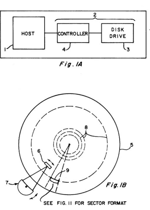
BRIEF DESCRIPTION OF THE DRAWINGS FIG. lA is a generalized block diagram of a data processing system in which the present invention may be utilized;
FIG. lB is a diagrammatic illustration of a disc sur-face in the disk drive of FIG. lA. according to the invention;
FIG. lC is a diagrammatic illustration of the logical spaces provided on a disk, according to the present invention;
FIG. 2 is an exemplary procedure for reading infor-mation protected by the multi-copy mechanism dis-closed herein;
FIG. 3 is an exemplary procedure for writing infor-mation onto a disk according to the multi-copy protec-tion mechanism;
FIGS. 4A-4D are a flow chart of the bad block re-placement procedure of the present invention;
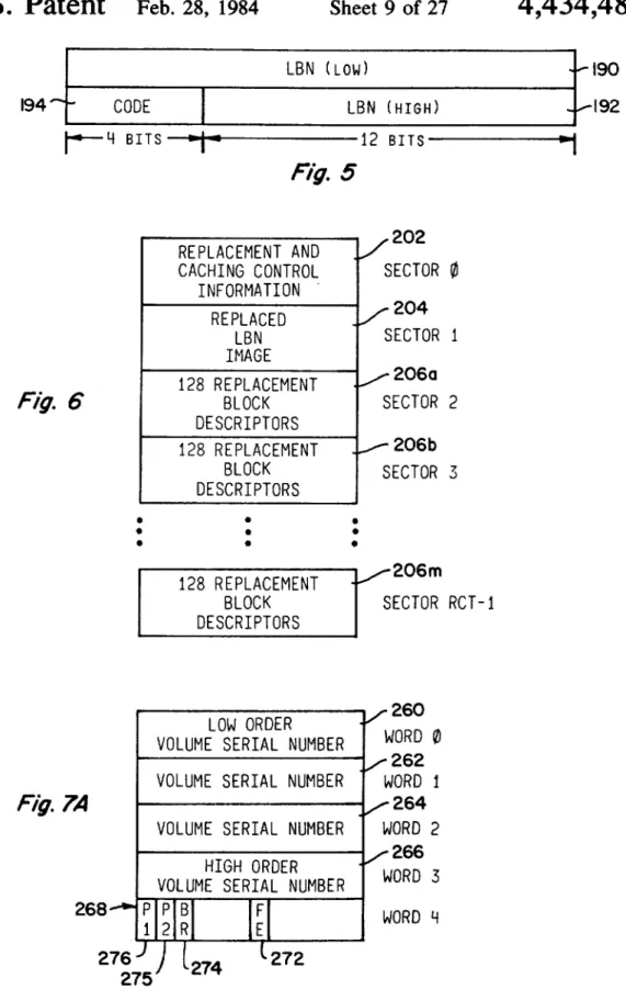
FIG. 5 is a diagrammatic illustration of the format of a replacement block descriptor;
FIG. 6 is a diagrammatic illustration of the structure of the replacement and caching table (RCT) of the present invention;
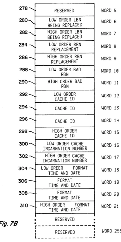
FIGS. 7A and 7B are a diagrammatic illustration of the contents of sector zero of the RCT of FIG. 6;
FIG. 8 is a diagrammatic illustration of the RCT search algorithm of the present invention;
FIGS. 9A-9C, together, are a listing of an exemplary procedure for implementing the RCT search alogrithm of FIG. 8;
FIG. 10 is a listing of an exemplary procedure for implementing the RCT hash algorithm described herein;
FIG. 11 is a diagrammatic illustration of the sector format employed by the present invention;
FIG. 12 is a diagrammatic illustration of one-fourth of the sector header of the sector format of FIG. 11;
FIG. 13A is an exemplary listing of a routine for generating an error detecting code usable in the present invention;
FIG. 13B is an exemplary flow chart for operating the controller 4 of FIG. lA in accordance with this invention to utilize a so-called forced error indicator when a sector is read from a disk;
FIG. 13C is an exemplary flow chart for operating the controller 4 of FIG. lA in accordance with this invention to utilize (or not utilize. as appropriate) the forced error indicator;
FIG. 14 is a diagrammatic illustration of a response from drive to controller. providing certain drive char-acteristics;
FIGS. ISA and 15B, together. are a diagrammatic illustration of a response providing certain other char-acteristics for a designated drive subunit;
FIG. 16 is a diagrammatic illustration of the first two and the last tracks of the LBN/RBN space of a drive;
FIG. 17 is a diagrammatic illustration of the first two and the last tracks of the XBN space of a drive;
FIG. 18 is a diagrammatic illustration of the first two and the last tracks of the DBN space of a drive;
5
4,434,487
FIG. 20 is a listing of a procedure for determining a replacement block's sector address;
FIG. 21 is a listing of a procedure for determining an external block's sector address;
FIG. 22 is a listing of a procedure for determining a 5 diagnostic block's sector address;
FIG. 13 is a listing of an exemplary procedure for reading 128 copies of an RBN's header to determine reliably the correct value of that header;
FIG. 14 is a diagrammatic illustration of the format of 10
a copy of the FCT (format control table) in the XBN space of the present invention; and
FIG. 25 is a diagrammatic illustration of sector zero of each FCT copy.
DETAILED DESCRIPTION OF A PREFERRED 15 EMBODIMENT
A generalized block diagram of a data processing system which can utilize the present invention is shown in FIG. 1. That system includes a host computer 1 (hav- 20 ing a central processor, main memory and input/output devices, not shown) and a secondary storage subsystem 2. The secondary storage subsystem, in tum, includes a disk drive 3 and a controller 4 for that disk drive. The controller 4 typically contains one or more processors 25 of its own and provides proper signals for actuating the drive to read or write information in accordance with instructions from the host processor.
The present invention utilizes a unique disk format to improve defect handling and reduce access time. It 30 further serves to protect certain selected areas of a disk . by storing multiple copies, and facilitates adaptation to peripheral device timing characteristics. This format comprises an architecture composed of three layers. First, there is a physical layer, comprising the actual 35 bytes, sectors, and collections of sectors on the disk. This layer also includes an error detection and correc-tion mechanism. Second, there is a logical layer, which is the level at which the physical layer is addressed and grouped into spaces, with particular uses assigned to 40 those spaces. Third, there is a functional layer, which is the level at which the use of data fields in each space is described. This layer includes the handling of bad blocks, if required, and other format usage information.
What follows generally is a detailed description of 45 each of those layers. Before proceeding, however, it will prove useful to define certain terminology used herein.
A "sector" is the smallest unit by which data is ad-dressed physically on a disk surface. Each sector occu- 50 pies a specific physical position relative to an index location on a disk, and has the property that it is avail-able for reading or writing once per disk rotation.
Sectors are grouped together hierarchically for ad-dressing purposes. First, a disk surface is divided into 55 one or more "cylinders." In turn, cylinders are divided into "groups;" and groups are divided into "tracks."
A "track" is a logical entity comprising a set of sec-tors occupying contiguous logical disk locations.
A "group" is, in tum, a logical entity representing a 60 set of tracks such that individual tracks in a group can be selected within the inter-sector rotation time. Tracks in the same group are "aligned" such that the same physical sector address is available simultaneously for reading or writing on all tracks in the group. 65
A "cylinder" is a logical entity representing a collec-tion of groups which can be selected via an operation with latencies less than the minimum "seek" time.
Cyl-6
inders have the additional property that the selection of a new cylinder requires the longest average head-posi-tioning operation. Groups within a cylinder are offset such that spiraling between adjacent graps is accom-plished without the loss of a full revolution of the disk. The terms track, group and cylinder simply relate collections of sectors to each other as a function of access time considerations. They are independent of physical organization or construction of the device.
The "sector number" portion of a sector address is always the low order portion. The "track number" portion of a specific sector address is always the middle portion of that address between the group and sector portions. The "group number" portion of a specific sector address is always a middle portion of that address between cylinder and track. The "cylinder number" portion of a specific sector address is always the highest order portion of that address.
A "bad block" is a sector containing a defect which either (1) causes an error exceeding the correction capa-bility of the error correction scheme used by the subsys-tem, or (2) exceeds a drive-specified error threshold beyond which the continued integrity of data in the sector cannot be guaranteed. A bad block may also be a sector which is defective to such an extent that, while data integrity is still assured, the overhead imposed by the required error correction procedure is greater than will be tolerated.
"Bad block replacement" is the designation of a spare sector (i.e., replacement block) to substitute for a bad block.
"Bad block revectoring" denotes the act of transfer-ring a read or write operation to the replacement block associated with a bad sector upon access thereto.
A "physical block number" (PBN) is a number which identifies a sector's physical position within the set of sectors on a mass storage device.
A "logical block number" (LBN) is a number identi-fying a sector's relative position within the set of sectors directly accessible to the host. These are used for host data storage and revector control information.
A "replacement block number" (RBN) is a number which identifies a sector's relative position within the set of sectors used as replacements for bad sectors.
A "primary replacement block" is a replacement block with a designated RBN on a track which has been allocated to replace a logical block on the same track. A "secondary replacement block" is a replacement block which is not a primary replacement block. It is either not the replacement block with the designated RBN of the primary replacement block on a track or is allocated to replace a logical block located on another track.
An "external block number" (XBN) is a number which identifies a sector's relative position within the set of sectors in the external format area.
A "diagnostic block number" (DBN) is a number which identifies a sector's relative position within the set of sectors in the diagnostic area.
A "host" is a central processing unit serviced by a secondary storage subsystem.
7
4,434,487
8
constrain a track into the logical (but not necessarily physical) structure of a ring. Similarly, a group is de-scribed as a collection of tracks wherein the time re-quired to switch from a sector at a given angular posi-In the "drive-unavailable" state, the drive is
operat-ing, is visible to, and may at times communicate with the controller; but the controller may not fully utilize the drive because the drive is "drive-online" to another controller.
A drive which is "drive-available" is one which is visible to, capable of communicating with, and capable of becoming (but is not currently) "drive-online" to any specific controller.
5 tion on one track to a sector at the next sequential angu-lar position on any other track is less than or equal to the time required to traverse the gap between adjacent sectors on the same track, during normal rotation.
It will also be helpful to define briefly a number of \0 generic symbols which will be used thorughout this description and in the accompanying drawings:
Customarily, in a dish drive a single head-positioning actuator will be used to position mUltiple read/write heads which are separated from each other by a fixed distance. When instructed to read or write, a controller determines which of the heads services the addressed Symbol Meaning portion of the disk and uses that head to perform the --~-C---S-ta::":'T--tin--g':;;c-y-li-nd-e-r--- 15 operation.
L Starting LBN Traversing the dislance between two logically adja-R Starting RBN cent tracks in adjacent groups may involve a head D
x Starting XBN switching time which exceeds the gap time. Therefore, Starting DBN
I LBN's per track according to this invention, in order to not lose a revo-RBN's per track 20 lution of the disk while the switching occurs, the first s t g o H Lc Xc Dc Ret
sectors per track sector (i.e., the sector with the lowest PBN) on all tracks per group
groups per cylinder tracks on the next higher-numbered group is offset an-Group offset gularly from the first sector on all tracks of the next LBN's in host area 25 lower-numbered group on the same cylinder by a num-LBN space size in cylinders ber of sectors sufficient to compensate for the head XBN space size in cylinders
DBN space size in cylinders switching time.
Size of one copy of replacement and caching For cylinders having more than one group, the sector
n table, in LBN's Number of copies of tables in non·revectored with the lowest physical block number on a track in the spaces 30 second group of the cylinder is offset from the index LcOgOtOr the number of replacement blocks mark on that track by a number of sectors representing Rs
Retpad Size of per RCT copy track/cylinder alignment at least the maximum switching time between the two
~~Iacement
and caching area size groups (modulo the rotation time). The third group onRsp
(nORct+ RctpadO(n-l» the cylinder would be offset by twice this value, etc. The Physical Layer
The sector is the basic addressable unit of the disk. A disk S, as shown in FIG. IB, is a circular platter having
35 Three examples will illustrate this logical addressing structure and definition:
Assume first that a drive has four disks and seven physical oxide surfaces used for data storage. Each data recording surface has two read/write heads associated therewith; switching between one physical head and another head on the same or any other oxide surface can be accomplished during the intersector time. Other than selecting one of the fourteen heads, however, there is nothing else that can be accessed without moving the heads via a cylinder switching (seek). As a result, the drive has a logical geometry of "14 tracks, one group, 560 cylinders."
Assume next the same physical configuration as above, implemented using a servo technology which requires a settling time larger than the intersector time when a head is selected. Like the above drive, this drive would have seven physical oxide surfaces used for data storage and two heads on each surface. Switching be-tween one head and any other head, however, would result in a head settling time greater than any intersector time, regardless of which oxide surface the head resides on. A switching of heads on such a drive would thus be accomplished via a group switching operation (group select). Other then selecting one of the fourteen data a coating of a ferromagnetic material on a rigid sub- 40
strate. For reading information from the disk or writing information to the disk, a transducer head 6 is posi-tioned by an actuator 7 over one of a number of concen-tric bands whose center lines are indicated by the nu-merals 8. Each "sector", such as a sector 9, is an arcuate 45 segment of such a band, of finite extent. Every sector is written in a predetermined format which includes a header, data bytes, error detecting code and error cor-recting code. Each header is, in turn, a 32-bit quantity that contains the logical address of the sector. There are 50 four copies of the header in every sector. The data bytes are application-specific information recorded on the disk by host and subsystem input/output operations. By convention there are either 512 or 576 bytes of data in every sector, when standard formats are employed. 55 (For example, the assignee's PDP-II and VAX-II com-puter systems use a 512 byte format, while its PDP-1O and DECSYSTEM-20 computer systems use a 576 byte format.) Sector layout is described in greater detail
below. 60 heads, however, there is nothing else that could be accessed on the current cylinder without moving the heads via a seek operation. The logical geometry of such a drive, therefore, is "I track, 14 groups, 560 cylin-ders."
"Tracks", "groups" and "cylinders" are collections of sectors grouped into a hierarchy of categories ac-cording to access time latencies. Access time to any sector on a track is a linear function of the distance of that sector from the current sector which is under the 65 read/write head, if on the same track. The first sector on the track immediately follows the last sector with respect to access time considerations. These properties
9
4,434,487
each physical arm would have multiple gaps located on it, each selectable in the intersector time. For discus-sion, assume eight such gaps per arm. Inter-head changes would be accomplished via group select opera-tions. Such a device would thus have a logical geometry 5 of "8 tracks, 14 groups, 560 cylinders."
All three of the above logical geometries, of course, were derived from the same physical geometry.
It is possible by changing the logical organization of a disk, to change its access time characteristics. Indeed, 10 proper redefinition of the logical addressing structure has been found to yield a possible average access time reduction of 5 to 6 percent, which is due to minimiza-tion of rotaminimiza-tional access latencies. It is difficult to gener-alize as to a technique for selecting the best logical 15 addressing arrangement for a particular drive, since there are a large number of physical parameters in-volved and some relate to host characteristics. So far, trial and error based on knowledgeable guesswork has proven successful. That is, a drive is exercised with a 20 large number of read and write operations and its aver-age access time are determined. A change in the logical structure is made (e.g., the number of groups is altered), the disk is reformatted and the drive is again exercised. This process is repeated as desired. The result is a logi- 25 cal format "tuned" to the physical characteristics of the host-controller-drive combination.
The Logical Layer
Attention is now directed to the logical layer of the 30 format. At this layer, the disk is divided into four ad-dress spaces of interest, as illustrated in FIG. lB. Two of these address spaces are in the set of sectors having an effect on the host; the other two are invisible to the host. (Specific implementations may have additional 35 address spaces which are not visible to the host). The first address space 12 contains the set of LBN's which are visible to the host. This LBN space is subdivided into two areas: the host applications area 12A and the Replacement and Caching Table (RCT) area 12B. For a 40 given sector size, the host applications area 12A is of constant size with respect to the number of usable blocks; that is, it is "bad block free." The RCT area 12B
10
native formats as may be available (e.g., 512 or 576 bytes/sector). The media error lists comprise a Format Control Table (FCT), which is a table containing infor-mation regarding blocks found to be bad at the time of manufacture.
Area 18 contains the diagnostic cylinders (DBN's). This area is inaccessible to the host and is utilized solely by diagnostics executing out of the mass storage subsys-tem.
The mass storage subsystem is responsible for utiliz-ing the logical blocks and replacement blocks in a fash-ion presenting the host with a logically contiguous set of blocks numbered from 0 to H - 1 for each unit, where H is the block capacity of the host applications area of the unit, as seen from the host. Allocated replacement blocks belong to one of two performance classifications: (I) primary replacement blocks and (2) secondary re-placement blocks. Primary rere-placement blocks are those allocated in the simplest (and usually fastest) man-ner, such that a negligible amount of time (i.e., at most one rotation) is used to access them during revectoring. Secondary replacement blocks are those that are deter-mined in a more complex fashion and normally require greater than one rotation time to access them during revectoring (i.e., a group selection or seek).
The Functional Layer
The functional layer comprises bad block handling. Two bad block handling mechanisms are used on the media. These are: (I) the use of multi-copy structures and (2) replacement and revectoring. The former pro-tects from failure by recording multiple copies of im-portant fields; the latter is a mechanism that replaces bad sectors with spare sectors which are reserved for that purpose. These mechanisms are used in different areas and have two fundamentally different effects.
Multi-copy structures are allocated in the RCT and FCT area to provide protection for critical data struc-tures. Replacementirevectoring is used in the host ap-plications area to eliminate holes in the address space. Multi-copy structures are allocated in areas where replacement is either not possible or not desirable. An example of a multi-copy structure is the RCT described herein. In reading or writing a multi-copy structure, is not bad block free; it is protected by a multi-copy
error handling mechanism described below. 45 only one block of the logical structure may be accessed at a time. Each copy must be accessed sequentially, in ascending order. Error recovery and correction must be enabled for both read and write operations. The The RCT address space contains a list of RBN's
which are used to replace LBN's that have become unusable on devices susceptible to bad blocks. These RBN's comprise a second logical space, 14, and are the last r sectors of each track (where "r" is a drive-specific 50 parameter) in host applications area 12A. RBN space 14 is outside the LBN space 12 presented by the controller to the host so RBN's are invisible to the host (except for the performance implications they may have on alloca-tion policies and the size of the RCT area 12B of LBN 55 space 12). A replacement block number is converted to a specific physical device location by a series of trans-formations performed by the subsystem using parame-ters supplied by the storage device to the subsystem. These conversions are subsystem implementation- 60 dependent and are of no interest to the host.
The area 16 contains the XBN's which provide for-matting information. It is inaccessible to the host and always is written in a predefined format (e.g., 512 by-tes/sector) even if other areas (e.g., LBN space 12) may 65 be written in other formats. The contents of area 16 are multiple copies of format control information and media error lists to use when formatting the disk in such
alter-number of copies allocated is a device characteristic and must be chosen to ensure achievement of the error rate goals of the system. A typical value for n will be four. Each copy must be positioned on the physical medium such that a single failure will not invalidate all copies.
The Multi-Copy Read Algorithm