STATIC BEHAVIOUR OF PRECAST
COLD-FORMED STEEL-CONCRETE COMPOSITE
BEAMS WITH AN INNOVATIVE SHEAR
TRANSFER ENHANCEMENT
J M IRWAN
M G ARUAN
INTERNATIONAL CONFERENCE ON
SUSTAINABLE INFRASTUCTURE AND BUILT
ENVIROMENT IN DEVELOPING COUNTRIES
2-3 NOVEMBER 2009
International Conference on Sustainable Infrastructure and Built Environment in Developing Countries November, 2-3, 2009, Bandung, West Java, Indonesia
ISBN 978-979-98278-2-1
Static Behaviour of Precast Cold-Formed Steel-Concrete Composite Beams with
an Innovative Shear Transfer Enhancement
J.M. I r w a n ' * , A . H . H a n i z a h2,1. A z m i3, M . N . M . Soffl4, M . G A r u a n5
'''Faculty of Civil and Environmental Engineering, Universiti Tun Hussein Onn Malaysia ( U T H M ) , 86400 Batu Pahat, Johor, Malaysia
^ F a c u l t y of Civil Engineering, Universiti Teknologi M A R A ( U i T M ) , Shah Alam, Selangor, Malaysia
•Corresponding author: i r w a n @ u t h m . e d u . m y
Abstract
A new connection device, based on bent-up tab shear transfer enhancement called bent-up triangular tab shear transfer (BTTST), has been studied through a cold-formed steel (CFS)-concrete composite beam subjected to a static bending test. BTTST provides an alternative connector system unique to CFS where CFS sections are usually thinner than hot-rolled sections and welding of headed-stud shear connectors is inapplicable. Coupled with the back-to-back arrangement of two CFS channels where symmetricity of the built-up section is restored, the resulting composite floor system has been proven to possess adequate strength, stiffness and ductility properties under static loads. The work has shown specimens employed with BTTST increase the strength capacities and reduce end slips of the specimens as compared to those relying only on the natural bond between CFS and concrete.
K e y w o r d s : cold-formed steel (CFS), composite beams, precast b e a m s , shear transfer m e c h a n i s m s .
1. Introduction
Cold-formed steel (CFS) sections, usually between 1.2 and 3.2 m m thickness [1], have been recognised as an important contributor to environmentally responsible, sustainable structures in the developed countries, and C F S framing is considered a sustainable 'green' construction material for low rise residential and commercial buildings. Their u s e however limited to structural roof trusses and a host of non-structural applications [2].
O n e limiting feature of C F S is the thinness of its section that m a k e s it susceptible t o torsional, distortional, lateral-torsional, lateral-distortional and local buckling. Resorting to a composite construction of structural C F S sections and a reinforced concrete deck slab, minimises the distance from the neutral-axis to the top of the deck and reduces the compressive bending stress in the C F S sections and arranging t w o C F S channel sections back-to-back restores symmetricity and suppresses lateral-torsional and to a lesser extent, lateral-distortional buckling. T h e two-fold advantage promised by the system promotes the u s e of C F S sections in a wider range of structural applications.
Figure 1 Bent-up triangular tab shear transfer ( B T T S T )
2. Large-Scale Flexural Test P r o g r a m
T h e purpose of large-scale tests is to evaluate and determine the behaviour of CFS-concrete composite b e a m s . The specimens were tested by using four-point load bending test. Four-point load bending test is actually a flexural test w h i c h provides a pure bending m o m e n t section without any shear force occurred along the section.
2.1. CFS-Concrete Composite Beam Test Specimens
T h e beams are 3 m long and are spanning 2.7m between supports. T h e width of the concrete slab is 6 7 5 m m , calculated based on the value of one quarter span (span/4) [3,4,5]. The width is taken as the effective width, be by neglecting the lag effect. T h e thickness of the
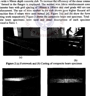
slab is 9 0 m m , chosen to represent the closer beam-to-beam construction. Cold-formed steel I-section b e a m w a s formed by back-to-back lipped channels with the top flanges cast into 6 7 5 m m w i d e x 9 0 m m depth concrete slab. To increase the efficiency of the shear connection, B T T S T formed in the flanges is employed. T h e welded wire fabric reinforcement consist of 8 m m diameter bars with grid spacing of 100mm x 100mm and steel grade 4 6 0 are used for the reinforcement. T h e use of wire meshes in the slab shown gave higher flexural stiffness and capacities then if rebars w e r e used instead [6]. Figure 2(a) and (b) show the formwork and casting work respectively. Figure 3 shows the composite b e a m test specimen. Total of 15 composite b e a m specimens w e r e used and detail descriptions of each specimen are summarized in Table 1.
(a)
(b)
[image:3.594.116.469.110.216.2]Figure 2 (a) F o r m w o r k and (b) Casting of composite b e a m specimen
[image:3.594.143.454.354.685.2]T a b l e 1 Composite B e a m Test Specimens Series Group Specimen Type of
E n h a n c e m e n t
Dimension ( m m x m m )
Angle (degree)
Spacing ( m m )
C F S Thickness
( m m ) L I L l a , L l b , L l c B T T S T 2 5 x 2 5 45 150 2.4
V J Z D L 2 L 2 a , L 2 b B T T S T 3 0 x 3 0 60 150 2.4
L 3 L 3 a , L 3 b Control - - - 1.9 L 4 L 4 a , L 4 b LYLB 2 5 x 2 5 45 150 1.9 G35 L 5 L 5 a , L 5 b B T T S T 3 0 x 3 0 60 150 1.9 L 6 L 6 a , L 6 b B T T S T 3 0 x 3 0 60 2 0 0 1.9 L 7 L 7 a , L 7 b B T T S T 3 0 x 3 0 60 150 2.4
2.2. TEST SETUP AND PROCEDURES
All precast cold-formed steel-concrete composite b e a m specimens w e r e tested using Universal Testing M a c h i n e ( U T M IPC 1000) subjected to four-point bending test system. Four-point load bending test is actually a flexural test which provides a pure bending m o m e n t section without any shear force occurring along the section. This situation can clearly be clarified from its shear force and bending m o m e n t diagrams. T h e shear force between the t w o loading points is zero and therefore provides a pure bending m o m e n t on that area. This test m e t h o d evaluates the flexural performance of toughness parameters by testing a simply supported b e a m under t w o concentrated loads. Each specimen supported with a pin at one end and a roller at the other end to indicate that the test is a simple support b e a m structure. T h e instrumentation setup is shown in Figure 4. Slips w e r e measured with transducers that w e r e attached at the top of the cold-formed steel lipped channels and the centerline of the slab cross section. A slip is defined as the difference in the deformation of the t w o elements. All measurements w e r e connected to a data logger.
F i g u r e 4 Instrumentation test setup
All of the composite b e a m s w e r e tested in the same manner. T h e load w a s applied using hydraulic r a m and measured with load cells placed above the r a m s . E a c h r a m applies load to a "distribution b e a m " that is supported by the test specimen. All loads from the r a m w e r e distributed to the t w o points on the test specimen. Initially, about 1 5 % of its predicted capacity w a s loaded onto the beam. Then it w a s unloaded w h e r e all m e a s u r e m e n t s w e r e "zeroed". This is to m a k e sure that the testing specimen is sitting on a proper position before testing is continued [4]. The load applied w a s then increased and all measurements after each increment w e r e recorded. Thereafter, the b e a m w a s loaded in increments of mid-span deflection until failure of the specimen w a s observed or until very large deflections happened.
3. T e s t R e s u l t
summarised in Table 2. T h e average results of each group of specimen w e r e used later for parametric study.
T a b l e 2 Experimental results
G r o u p Spec.
Ultimate Load, P„
(kN)
Average Pu
(kN)
Deflection at ( m m )
Average Su
( m m )
u l t i m a t e M o m e n t , (kNm) L l a 168.2 36.7
L I L i b L i e
168.2 166.9
167.8 35.2 45.3
39.1 113.3
L 2 L 2 a L 2 b
173.0
172.1 172.6
36.5
39.9 38.2 116.5 L 3 L 3 a
L 3 b
132.6
130.5 131.6
42.6
47.1 44.9 88.8 L 4 L 4 a
L 4 b
146.0
142.4 144.2
41.8
41.2 41.5 97.3 L 5 L 5 a
L 5 b
155.0
155.3 155.2
30.0
45.9 38.0 104.8 L 6 L 6 a
L 6 b
154.6
152.7 153.7
34.8
34.5 34.7 103.7 L 7 L 7 a
L 7 b
182.0
* 182.0 39.9 * 39.9 122.8 *Electrical interruption
4. P a r a m e t r i c S t u d y
4.1. Shear Transfer Enhancements
Testing for group L 3 , L 4 and L 5 w a s setup to investigate the effect of difference type of shear transfer enhancement in CFS-concrete composite beam. T h e ultimate load that can be sustained by each specimen is summarised in Table 3. It w a s found that the CFS-concrete composite b e a m s specimen with shear transfer enhancements showed an increase in capacities of ultimate moment, MU i e x p. Referring to Table 3 , the ultimate capacity of specimen
L 4 (with L Y L B ) is 9 . 6 % higher than that of specimen L 3 (without enhancement). L 5 (with B T T S T ) shows a 1 8 % increase in ultimate capacity over specimen L 3 . A comparison of the capacities of L Y L B and B T T S T indicates that the B T T S T result w a s 7 . 7 % higher than that of specimen L 4 with L Y L B . Therefore, it can b e concluded that the ultimate m o m e n t resistance of CFS-concrete composite b e a m s with B T T S T are better than CFS-concrete composite b e a m s with L Y L B .
T a b l e 3 Ultimate Strength of Composite B e a m s with difference shear transfer enhancement Group Type of E n h a n c e m e n t Ultimate M o m e n t , Mu,e Xp
(kNm)
Mu,exp Increment (%) L 3 Without enhancement (control) 88.8
-L 4 LYLB 97.3 9.6
L 5 B T T S T 104.8 18.0 7.7
4.2. Dimension of BTTST (size and angle)
T a b l e 4 Ultimate Strength of Composite B e a m s difference dimension of B T T S T Group Dimention of B T T S T Ultimate M o m e n t ,
Group
(LfxL
s, 0)
Mu. e xD ( k N m ) Increment (%)L I 25 x 25 , 45° 113.3
-L 2 30 x 30 , 60° 116.5 2.8
4.3. Degree of shear connection
T h e effect of the difference degree of shear connection is shown in Table 5. T h e table s h o w a decreased from 104.8kNm to 103.7kNm for specimen L 5 and L 6 , respectively as t h e bending m o m e n t reached its ultimate capacity. It is clear that the decreased is too small with the value about 1.1%. It is stated that the CFS-concrete composite beam practically b e design with partial shear connection for equal m o m e n t capacity b y reducing n u m b e r of B T T S T .
Table 5 Ultimate Strength of Composite B e a m s difference degree of shear connection
Group Degree of shear connection
Ultimate M o m e n t , Mu.e x„ ( k N m )
MU |eXp
D e c r e a s e (%) L 5
L 6
Full Partial
104.8
103.7 1.1
4.4. Thickness of CFS
Specimens group L 5 and L 7 w a s test to investigate the effect of difference thickness of C F S . Table 6 show a comparison between the ultimate moment, Mu, obtained experimentally
using 1.9mm thick and 2 . 4 m m thick C F S with B T T S T shear transfer enhancement. T h e ultimate m o m e n t w a s recorded at 122.8kNm from specimen with 2.4mm thick compared with 104.8kNm obtained from the specimen with 1.9mm thick. It is increased b y 17.2%. This result is also similar to result obtained from the w o r k done b y Lakkavalli and L i u [10]. T h e shear area (refer Figure 1) of the shear transfer enhancement increases w h e n t h e thickness is increase. Shear area acts as the resistance for shear transfer enhancement from bending. T h e bending capacity of the shear transfer enhancement increases with the increase of shear area.
Table 6 Ultimate Strength of Composite B e a m s difference thickness of C F S Group C F S thickness Ultimate M o m e n t , Mu > e Xp Group
( m m ) Mu.C X D( k N m ) Increment (%)
L 5 1.9 104.8
-L 7 2.4 122.8 17.2
4.5. Concrete strength
Concrete strength is o n e of the parameters considered in this large-scale experimental program. Table 7 shows ultimate m o m e n t s of tested specimens with fcu 2 7 . 7 1 N / t n m2 and
3 5 . 6 3 N / m m2. Specimens L 7 , with higher grade of concrete strength carried 1 7 . 3 % m o r e
ultimate m o m e n t than that of specimens L 2 . This is expected, since the higher grade of concrete h e n c e increases the capacity of a structure.
Table 7 Ultimate Strength of Composite B e a m s difference thickness o f C F S G r o u p Concrete compressive s t r e n g t h , ^ ,
( N / m m2)
Ultimate M o m e n t , Mu.C X D( k N m )
^^u,exp
Increment (%)
L 2 27.71 116.5
5 . C o n c l u s i o n s
Fifteen companion large-scale specimens w e r e tested to evaluate the strength and behavior of precast cold-formed steel-concrete composite b e a m s . T h e test results can b e summarized as specimens e m p l o y e d with shear transfer enhancements increase the strength capacities and reduced deflection of the specimens as compared to those relying only on a natural b o n d between cold-formed steel and concrete. In shear transfer enhancements investigated, B T T S T provided the best performance in terms of strength and deflection. Strength capacities of the CFS-concrete composite b e a m s also increase w h e n the dimension of B T T S T , thickness of C F S and concrete strength is increase. T h e CFS-concrete composite b e a m practically design with partial shear connection for equal m o m e n t capacity by reducing n u m b e r of B T T S T .
6. A c k n o w l e d g m e n t
The authors w o u l d like to thank the Ministry of Higher Education Malaysia ( M O H E ) , Universiti Tun Hussein Onn Malaysia ( U H T M ) and Universiti Teknologi M A R A (UiTM) for sponsoring this research.
7. References
Yu, W.K., Chung, K.F. & Wong, M.F. (2005). "Analysis of Bolted M o m e n t Connections in Cold-Formed Steel B e a m - C o l u m n Sub-Frames". Journal of Constructional Steel Research 6 1 : 1 3 3 2 - 1352.
Shaari, S.N. and Ismail, E. (2003). "Promoting the U s e of Industrilised Building Systems and M o d u l a r Coordination in the Malaysian Construction Industry". Board of Engineers Malaysia. Bulletin Ingenieur (March 2003): 6 - 8 .
B S 5 9 5 0 (1990). "Structural use of steelwork in building: Part 3: Design in composite construction — Section 3.1 C o d e of practice for design of simple and continuous composite b e a m s " . British Standards Institution, London.
Lawson, R . M (1990). " Commentary on BS5950:Part 3 : Section 3.1 ' C o m p o s i t e B e a m s ' " . Steel Construction Institute. Berkdhire.
Richard Yen. J . Y , Yiching Lin, Lai. M.T. (1997). " C o m p o s i t e B e a m s Subjected to Static and Fatigue L o a d s " . Journal of Structural Engineering A S C E . 123(6):765-771
R. Abdullah, M . M . Tahir and M . H . O s m a n (1999), "Performance of C o l d - F o r m e d Steel of Box-Section as Composite beam." 6t h International conference on Steel and Space
Structures. Singapore.
M . Irwan J., Hanizah A.H., A z m i I., B a m b a n g P., H.B K o h , Aruan M.G. (2008). " S h e a r Transfer E n h a n c e m e n t In Precast Cold-Formed Steel-Concrete Composite B e a m s : Effect of B e n t - U p Tabs Types and Angles". Technology and Innovation for Sustainable Development Conference (TISD2008), Faculty of Engineering, K h o n K a e n University, Thailand. 28-29 January 2008
M . Irwan J., Hanizah A.H., A z m i I., B a m b a n g P , H.B K o h , Aruan M . G (2008 )."The effect of bent-up tabs shear transfer enhancement shapes, angles and sizes in precast cold-formed steel-concrete composite b e a m s " . Fourth International Conference on High Performance Structures and Materials ( H P S M 2008), T h e Algarve, Portugal. 1 3 - 1 5 M a y 2 0 0 8 .
J. M . Irwan, A.H. Hanizah, I. A z m i . "Test of Shear Transfer E n h a n c e m e n t in Symmetric Cold-Formed Steel-Concrete Composite B e a m s " . Journal of Constructional Steel Research 65 (2009) P p . 2087-2098