Journal of Chemical and Pharmaceutical Research, 2013, 5(12):697-703
Research Article
CODEN(USA) : JCPRC5
ISSN : 0975-7384
An intelligent flight chess robot design and implementation
Jiansheng Peng
1,2, Qiwen He
2*, Qingjin Wei
2,
Yong Qin
2, Marong Pan
2, Baoying Lin
2,
Cunbin Guo
2, Zhuocheng Huang
2, Degui Yang
2,
Changfeng Liang
2and Siyuan Luo
21
National Key Laboratory of Communication, UEST of China Chengdu, China
2
Department of Physics and Mechanical & Electronic Engineering, Hechi University, Yizhou, China
_____________________________________________________________________________________________
ABSTRACT
The field of education and entertainment for robotic applications, in order to better take into account the robot teaching and entertaining, intelligent flight chess developed a robot system. The system consists of two robots and a dice composition for the control of robot AT89S52 microcontroller core, using NRF24L01 wireless module for communication between the robot and the dice, dice AT89S52 through detection ADXL345 three-axis sensor module to control the corresponding points robot motion. Experimental results show that at a given flight chess drawings, two robots are able to move according to the dice points to the corresponding position, to achieve the ultimate game, the system can be applied to areas such as education and entertainment and so on.
Key words: Robot, Flight Chess, Three-axis Acceleration
_____________________________________________________________________________________________
INTRODUCTION
Dual function of both study and entertainment electronic toys popular with the children, today's science and technology as yesterday's rock and roll: Most of the parents, even their claim is cool, also can't keep up with the trend. Nowadays, people have found a balance between technology and entertainment in the new technology products. Many high-tech products are particularly popular with children and young people, as they adapt to their lifestyle, needs, and teach them how to integrate with the growing electronic world [1]. However we are familiar with this kind of toy of flight chess. So we can broaden thinking, combined with the existing single chip microcomputer technology, voice broadcast technology, wireless communication technology to make this game into electronic toys. There are such high demand of product, for example, football robot, intelligent chess robot, go bang robot etc. Not only need image recognition, processing, algorithm, and the cost is very high. In the field of current education and entertainment is difficult to get promotion and popularization[2,4]. Not only need to design simple smart board device, but also the development of low price. This design can also carry voice module simulation dialogue scenes when people play chess. Therefore, how to do intelligent chess robot can give attention to both teaching and entertainment become the intelligent robot is an important research direction in the field of study.
THE SYSTEM DESIGN
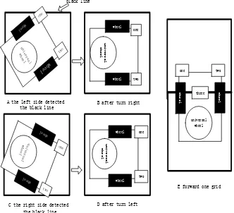
grid, constantly testing on both sides of the black line and adjusting the robot walks on the grid. Until there is a robot to reach the finish line first.
AT89S52
black line detection
module
voice module power
supply module
steering gear
wireless module
AT89S52
black line detection
module
voice module power
supply module
steering gear
wireless module
AT89S52
power supply module
wireless module three- axis
[image:2.595.89.529.105.539.2]acceleration module
Fig. 1. System Structure
Fig. 2. Flight Chess Board
HARDWARE DESIGN
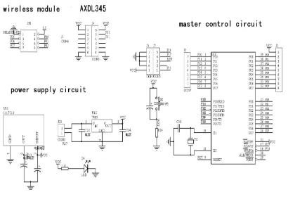
Whether the system can operate steadily or not is based on the hardware design. The robot part is designed by using AT89S52 as its master controller, NRF24L01 as the communication interface, WT588D module to conduct voice broadcast, NE555 to modulate 38KHZ signal for transmitting circuits and HS-38B for receiving circuits to detect the black line, and using a servo as the drive. In order to detect the six faces of the dice, the dice part should be made up of AT89S52 as master controller, NRF24L01 as the communication interface, and three-axis acceleration sensor.
The Robot Hardware Design
Fig. 3. The Whole Principle Diagram of Robot
Black line Detection Circuit
The circuit mainly works by NE555 producing about 38KHZ premature beat to infrared emission tube D15. If HS-38B receives infrared light, OUT pin will be of high level. However, the transmitted infrared light will be absorbed when the robot meets the black line. Thus, HS-38B can not receive signal, and OUT pin changes into low level. Accordingly, the black line can be detected. The Schematic diagram is shown in Fig.3. The distribution of infrared sensor is shown in Fig.4, among which the first sensor and second sensor are mainly responsible for detecting the black line of two sides (left and right) and making sure that the robot will always stay within the bound when moving forward. While the major function of the third sensor is to detect bars, and the fourth and fifth sensor is to detect the black line of both sides when drawing back.
wheel wheel
universal wheel
one two
four five
three
Power Supply Design
The voltage regulator circuitry uses a 7.4v lithium polymer battery, the 5V output voltage from 7805 is supplied to the single chip, the servo, and the infrared transceiver circuit, and the 3.3V output voltage from LM1117-3.3 to the voice module and the wireless module .The schematic of the power module is shown in Fig.3.
Wireless Module
NRF24L01 is a 2.4G band wireless module, which is characterized with low cost, low power consumption, high transmission rate, its simple software design, and the stable and reliable communication [5]. The wireless module circuit is shown in Fig. 3.
Voice Module
WT588D is a kind of a single voice chip, produced by Guangzhou Wei chong electronic co., LTD. It is powerful in functions and can be repeatedly erasable and programmed. With WT588D, a voice chip is no need to find any peripheral single-chip circuits as its controlled manner, for the highly integrated single-chip technology can be sufficient to replace the complex peripheral control circuit [6]. One-line serial mode is used for the design, so only a data cable can conduct the operation. The voice module circuit is shown in Fig. 3.
Dice Hardware Design
[image:4.595.103.513.408.688.2]Dice use ADXL345 triaxial acceleration sensor to identify which face up. ADXL345 is the three-axis digital acceleration sensor of ADI company, is mainly used in consumer electronic micro inertial device, perceived 16g maximum acceleration,sensing accuracy up to 3.9mg/LSB, Angle measurement typical error is less than 1 degree [7]. The principle of dice is that AT89S52 read the value of X, Y, Z axis in which ADXL345 master controller module, dice number is 1 when defining the X, Y, Z values of the acceleration is 1g, 0,0, dice number is 2 when defining the X, Y, Z values of the acceleration is 0,1g,0, dice number is 3 when defining the X, Y, Z values of the acceleration is 0,0,1g, dice number is 4 when defining the X, Y, Z values of the acceleration is 0,0,-1g, dice number is 5 when defining the X, Y, Z values of the acceleration is 0,-1g,0, dice number is 6 when defining the X, Y, Z values of the acceleration is -1g,0,0, thus, the dice corresponds to one of 1 to 6 when going to a positive value, then sending the data through wireless module. The overall schematic diagram of dice shown in Fig. 5.
Fig. 5. The Overall Schematic of Dice
SOFTWARE DESIGN
(2) Robot B programming mainly implements: initialize the wireless module, and then wait for robot A to send data to come over, then wait for coming data after people throwing dice, after how much voice broadcast, walking to the corresponding position of the board, and then send data to robot A, waiting for robot A to send data back, until one coming to an end when ending. Robot B program flow chart shown in Fig. 6.
wireless module initialization
waiting for data from robot
A
received data from the dice
walking on the corresponding
of grids wireless module
initialization
waiting for data from the dice
received data from the dice
walking on the corresponding
of grids
sending data to the robot B
received data from the second
robot start
sending data to the robot A
stop and prompt voice end end Yes Yes No arrived the finish line No start arrived the finish line No
the flow chart of robot A
[image:5.595.92.523.113.682.2]the flow chart of robot B
the infrared sensors(left) detected the black line the infrared sensors(center) detected the black line the infrared sensors(right) detected the black line turn right grids plus one turn left the infrared sensors(center) detected the black line the infrared sensors(right) detected the black line grids plus one turn left the infrared sensors(left) detected the black line turn right stop and prompt voice YesFig. 6. Robot Program Flow Chart
initializes the wireless module and three axis
module
continuous reading the value of the three axis
sensor
detect whether a face up or not
sending data of dice
reset data start
Yes No
Fig. 7. Dice Program Flow Chart
TESTING RESULTS AND ANALYSIS
It is found that the robot cannot receive data and step out of the grid sometimes after having tested several times, and now the analytical and countermeasure will be offered as follows.
(1) In the aspect of wireless telecommunications. Data were found missing during the experimental process, which can be solved by sending two NRF24L01 modules frequently or avoiding sending them simultaneously.
un iv er sa l wh eel whe el whe el u n i v e r s a l w h e e l wheel wheel one two u n i v e r s a l w h e e l whe el whe el one two u n i v e r s a l w h e e l wheel wheel universal wheel two two one one one two
A the left side detected
the black line B after turn right
D after turn left black line
C the right side detected the black line
E forward one grid
[image:7.595.140.472.83.385.2]w h e e l w h e e l three
Fig. 8. Black Line Detection and Adjusting Map
CONCLUSION
All the functions of the design are implemented, can stability walk on the grid, stability to send and receive data, automatically detect whether dice had been thrown. Robot should be combined with real life, let it do more for us, we need more such interesting designs to arouse our interest in robots. Not only design can be used in children's educational toys, but also can be used in the direction of the electronic teaching platform, DIY design, etc.
Acknowledgements
The authors are highly thankful for the Guangxi Natural Science Foundation(ID: 2013GXNSFBA019282), Guangxi university research projects (ID: 2013YB205), Hechi College special projects (2003ZX-N003), Chinese College Students' Innovative Entrepreneurship Training Program(ID: 201310605008, 201310605009, 201310605010) and Guangxi Students Projects of Innovation and Entrepreneurship Training Program (ID: 1100, 1101, 1109, 1110, 1111).
REFERENCES
[1]Katsumoto, Yuichiro,Tokuhisa, Satoru,Inakage, Masa ,Ninja Track: Design of electronic toy variable in shape and flexibility,TEI 2013 - Proceedings of the 7th International Conference on Tangible, Embedded and Embodied Interaction, Barcelona, Spain, 2013, 10:17-24.
[2]YANG Li, SHU Jun, ZHONG Luo, International Journal of Digital Content Technology and its Applications ,
2012,6(12):182-188.
[3]He, Jilin , Chen, Zhixian, Applied Mechanics and Materials, 2013, 271(1):1536-1540.
[4]YANG Yun-qiang,WU Jiao, Science Technology and Engineering, Vol. 12,No. 5 Feb,2012, pp. 1052-1055. [5]CHEN Li-juan, CHANG Dan-hua, Chinese Journal Of Electron Devices, 2006,29(1):248-250.
[6]Peng Jiansheng, Li Xing, Qin Zhiqiang, Li wei. Journal of Digital Information Management, 2012,10:277-283.