International Journal of Emerging Technology and Advanced Engineering
Website: www.ijetae.com (ISSN 2250-2459,ISO 9001:2008 Certified Journal, Volume 4, Issue 9, September 2014)
581
I. Real Time Expert System for Alarm Diagnosis in A Thermal
Power Plant
Latha B. Kaimal
1, Abhir Raj Metkar
2, Rakesh G
3, Lekshmi G
4, Saranya Sreekumar
5 1, 2,3,4,5Control and Instrumentation Group, CDAC (T)
Abstract— Growing complexity of real world applications demands for the need to integrate Artificial Intelligence techniques in traditional real time systems. An expert system (ES) is a software that attempts to accumulate the knowledge of domain experts and increase the performance of users to solve problems in a specific domain, that are difficult enough to require significant expertise. Real-Time Knowledge Based Systems (RTKBS) have been used to tune controllers, supervise the performance of adaptive controllers, perform fault detection and diagnosis, perform alarm management and even provide direct on-line process control. The large number of process parameter values is changing with time in a Power Plant. These parameters are part of rules framed by domain experts for the expert system. Real Time Expert System helps in the smooth functioning of complicated industrial processes and help in recognizing problems associated with it.
This paper describes the Real Time Expert System Shell as an integrated software tool which can be used to develop Intelligent System for Alarm Diagnosis and Root Cause Analysis and operator guidance in process plants. The Shell uses a Hybrid Knowledge Base consisting of mainly Meta Rules, Rules and Frames. It interfaces with the external SCADA System via OPC module which acquires on line plant data and identifies (processes) Alarms for diagnosis.
Keywords— Expert system, Knowledge Base System,
Customizable Data Interface, Inference Engine, Event
Processor.
I. INTRODUCTION
Knowledge Base System (KBS) are system that utilizes artificial intelligence (AI) approach to give guidance in a particular domain by applying human expert knowledge. In process plants, fault diagnosis involves a lot of challenges starting from commonly occurring malfunctions to rarely occurring emergency situations. KBS can play an important role in process plants as it helps human operators to identify faults by capturing problem solving capability of domain experts. KBS can be represented in a number of ways such as rules, frames etc. Inference engine utilize this Knowledge Base (KB) for fault detection and diagnosis. iRESS is a software development environment containing the basic components of expert systems (ES).
This toolkit can be used to develop Intelligent Systems for the alarm Diagnosis, Root Cause Analysis and operator guidance in process plants etc. For a particular application development using the Expert System Shell (ESS), the Knowledge Base has to be developed with rules and attributes relevant to the target system.
This tool has an object-oriented environment that allows creation of Hybrid Knowledge Base. Expert‘s knowledge is encoded as a set of frames and rules and the Inference engine does knowledge inference using either built-in backward or forward chaining. In a particular domain, problem-solving and decision-making can be done by the applications developed with iRESS.
II. ARTIFICIAL INTELLIGENCE
AI is the capability of a machine to imitate intelligent human behavior. The central principles of AI include reasoning, knowledge, planning, learning, communication, perception and the ability to move and manipulate objects. AI research has developed some highly successful methods for dealing with uncertain or incomplete information, employing concepts from probability and economics [1]. In process industries, AI techniques have been used for some years now. The main characteristic of the application of AI techniques, especially ES is the simulation of plant expert‘s actions.
International Journal of Emerging Technology and Advanced Engineering
Website: www.ijetae.com (ISSN 2250-2459,ISO 9001:2008 Certified Journal, Volume 4, Issue 9, September 2014)
582
III. EXPERT SYSTEM
An ES is a system that solves problems that normally requires domain expertise by incorporating experts‘ knowledge in a computer. In the last few years, ES have been widely used to solve critical problems in process plants. The knowledge required for building such system has to be collected from experienced operators and power plant parameters, layout and specifications.
[image:2.612.394.496.135.332.2]Expert system (ES) can significantly reduce the work load on plant operators and experts, and act as an expert for plant fault diagnosis and maintenance. In power plant control centers, an important part of these systems are intended to work in ‗real time‘ as on-line applications. These applications address such issues as intelligent alarm processing for fault diagnosis and operator guidance. In fact, the use of expert systems for real-time applications in power plants control centers is highly demanding due to the characteristics of these applications.
Figure 1. Expert System Components
[image:2.612.52.292.352.445.2]In rule based expert systems expert knowledge is expressed in terms of if-then rules. The ES components as in Figure 1 includes Inference Engine, Knowledge Base, User-Interface [4]. Expert System Shells are Expert Systems with empty knowledge base but have all other components like Inference Engine, GUI and Knowledge Base Structure. ES‘s are often used in Intelligent SCADA and offline training systems for non-expert operators. In real time monitoring and/or control, more applications are currently using ES mainly on topology estimation and fault diagnosis. In developing an ES, it is important for us to know the criteria that are needed to build a successful system [5]. Different stages of development of ES are shown in Figure 2.
Figure 2 . Expert System Development Stages
INTELLIGENT DECISION SUPPORT SYSTEMS: Intelligent Decision Support Systems (IDSS) add intelligence to existing systems to enhance problem solving ability. Decision Support Systems (DSS) are used to enhance user ability to make decisions efficiently. The ultimate decision is taken by the user. IDSS is a result of combining DSS and AI [5]. IDSS are used for capturing, organizing and reapplying knowledge including decision rules and criteria [6].
IV. DEVELOPMENT AND IMPLEMENTATION OF IRESS FOR
ALARM DIAGNOSIS IN ATHERMAL POWER PLANT
A. Introduction
In a Thermal power plant, steam is used to drive a steam turbine. This turbine is connected to an electrical generator. After this, the water is condensed, and may be used again.
Statistics showthat, about 65% of the electricity consumed
International Journal of Emerging Technology and Advanced Engineering
Website: www.ijetae.com (ISSN 2250-2459,ISO 9001:2008 Certified Journal, Volume 4, Issue 9, September 2014)
583
ASTeC(Automation Systems Technology Centre) is a national level R&D programme taken up by C-DAC Thiruvananthapuram and funded by Dept. of Electronics and Information Technology (DeitY) under Ministry of Communications & Information Technology (MCIT), Govt. of India. C-DAC (T) is currently executing a number of R&D projects under the ASTeC Programme. One of the
R&D projects in the Technology Programme
‗LEARNING‘ is ―Development of Real Time Expert System Shell with Learning and Failure Forecast Engines‖ which involves development of a Real time Expert System Shell. The Shell toolkit can be used to develop Intelligent Operator Guidance System for Diagnosis and Root Cause Analysis of alarms and faults in process plants. The overall architecture of the ES Shell is as given in Figure 3.The basic components of the Shell are Customizable Data Interface (CDI), Event Processor, Inference Engine, Knowledge Base, Knowledge Base Editor and Web based GUI for providing Operator guidance. Additional (Optional) modules are Learning Engine and Forecast
[image:3.612.60.276.385.556.2]module
.
Figure 3. Architecture Of Expert System Shell
B. Knowledge Representation
Knowledge Base (KB): The system uses a Hybrid Knowledge base. Meta Rules, Rules and Frames are the
main components of KB. Domain expert inputs different
rules using user friendly web based Knowledge Base Editor (KBE). Rules and Frames, Temporal information from SCADA is used for root cause analysis of faults. The various parameters required for alarm diagnosis including online SCADA data are stored in a database.
In this development knowledge-based model of the plant or target system is used. MySQL RDBMS is used for Knowledge Base.
Different Structures used to store knowledge are:
1)Meta-rule- Structure:If <Condition> Then <Action>. Meta-Rules are the supervisory rules to categorize Sub-rules in broad areas or nodes. It decides which rule should be fired next or the order in which rules are to be applied. These rules help to minimize the time of inference to reach to the root cause. Meta rules thus help in increasing the efficiency of the system [7]. Metarules and rules are distinguished by a metarule identifier field.
2)Rules- Structure: If <Condition> Then <Action>. Rules are basic components of the ‗Knowledge base‘. The condition and action parts of the rules are defined by user defined variables called Tags/Parameters. Logical operators separate the condition and action parts having more than one parameter. There are different types of parameters namely process plant tags from OPC server, and user defined variables. For each rule there is a ‗priority factor‘ to be configured. The set of rules are taken in the order of this ‗priority factor‘.
3) Frames: Frames are general data structure holding the static information about any equipment or unit. A frame comprises a frame name, slots or attributes of the frame and facets [8][9].The concept of a frame is defined by a collection of slots. A slot may contain a default value or a pointer to another frame or a set of rules. During inferencing, if the parameter type is ‗frame‘, its corresponding value is taken from the slot of the frame. If the slot value is rule name, that rule will be taken next for processing.
4) Parameters: All the Plant data or Tags are termed as Parameters. Parameter can be of GUI Type, Database, Frame or Function type.
5)Functions: Functions are used for implementing specific calculations like average, rate of change etc. If the parameter type is ‗Function‘, it is associated with a specific Function and parameters. In Mill-A System trouble alarm diagnosis, rate of change function is used.
C. Data Interface Module
International Journal of Emerging Technology and Advanced Engineering
Website: www.ijetae.com (ISSN 2250-2459,ISO 9001:2008 Certified Journal, Volume 4, Issue 9, September 2014)
584
The input data is preprocessed by CDI and fed to the Event Processor module. CDI is an OPC client utility with alarm configuration facility. In this project implementation, the CDI interfaces with the external SCADA system and use OPC connectivity to read the tag data. The online data are logged into a database. The Interface to applications are:
TCP/IP Communication with the DCS system
OPC Connectivity (OPC –DA)
OPC Data Access (OPC –DA) is a group of standards that provides specifications for communicating real-time data from data acquisition devices such as PLCs to display and interface devices like Human-Machine Interfaces (HMI). The specifications focus on the continuous communication of data. There are three attributes associated with OPC DA. These are a value, the quality of the value, and a timestamp. The OPC DA specification states that these three attributes have to be returned to an OPC client making a request.
Overall features of CDI are,
1)Configure Tag information:Read Tag configuration
from external system (e.g. Using OPC client) and Select Tags for monitoring
2)Display configuration data :This feature enables the
user to view all the tag names and their configuration parameters/settings like signal type(Analog/Digital), High/ HighHigh limits, Low /LowLow limits etc.
3)Set Alarm priority: The user can set high priority for
alarms to be monitored.
4)Log Tag and Alarm Information to the database.
5)This module reformats the data received from OPC
[image:4.612.325.541.136.349.2]client and sends to Event processor
Figure 4.CDI Module Architecture
As shown in Figure 4, The Service Configurator retrieves the OPC Server details and configures OPC communication service. Using this service details, the OPC client will retrieve the online OPC tag data from the OPC Server. The Alarm Processor will identify the Alarms occurring and logs the Alarm details to the database and updates the common memory area. The Historic Data Logger will log the OPC Tag data to the database.
OPC Client uses the Service configuration details and connects to remote/local machines containing registered OPC Servers. It starts the OPC Client service and listens for the events that are configured to each Tag groups.
International Journal of Emerging Technology and Advanced Engineering
Website: www.ijetae.com (ISSN 2250-2459,ISO 9001:2008 Certified Journal, Volume 4, Issue 9, September 2014)
585
Event Processor module takes the real-time data output of CDI for processing and triggering inference in Expert System. Different types of alarms in real time are processed by the Event Processor module and it classifies and sorts the alarms based on priority. For the triggering of the Inference Engine these alarms are used.
D.Inference Engine
The Inference Engine (IE) is the heart of the expert system.IE uses knowledge from KB to arrive at a conclusion on the actions to be taken. Here the expert system is intended for fault diagnosis. So a Backward Chaining inference strategy is preferred. Inference engine uses rules and frames stored in KB for backward reasoning method to arrive at a conclusion. In Backward Chaining input to the inference engine is the highest priority Alarm from Event processor (CDI) module. Internal block diagram of Inference Engine is shown in Figure 5.
Working Principle of Inference Engine: When a critical alarm occurs in plant, corresponding metarule will be fired first. Next, the condition part will be evaluated and if that condition part is true for any rule in KB, that rule will get fired. This repeats till the final root cause of the alarm is reached. The inference engine algorithms are as follows:
1) Backward reasoning: Backward chaining is a goal driven process, which uses KB to work backward from possible conclusions to the cause.
Consider an example of an ES for medical diagnosis and one wants to know whether the data of the patient supports the conclusion that patient is suffering from disease F. In backward chaining, initially the goal is to find evidence of disease F. Action part of all the rules in KB whose action part contains disease F is taken. Each rule is taken and condition part is examined. To support the disease F hypothesis, one has to show that the conditions are true. Now conditions become the goals of backward chaining. We need to find rules whose action-parts include these conditions as their conclusions, if the conditions are not supported directly by the contents of working memory. And so on, until either we have established a chain of reasoning demonstrating that the patient has disease F, or until we can find no more rules whose action-parts include conditions that are now among our list of goals.
2) Forward reasoning: In this mode of operation, the rule-based system is data-driven. The input to the Forward reasoning is the fault parameter. If there are multiple parameters they are sorted based on the certainty factor. The status of data decides which rules to fire and the data is added to working memory and then this process is repeated until a conclusion is reached.
3) Hybrid reasoning: Hybrid reasoning uses both
[image:5.612.342.544.175.311.2]forward and backward reasoning for inference, depending upon the data received.
Figure 5.Internal Block Diagram Of Inference Engine
Based on user input or SCADA input, Inference Manager processes rules. While processing it interacts with different modules such as Meta Rule Interpreter, Rule Interpreter, Frame Interpreter, Parameter Interpreter, Working Memory and Production Memory. Meta Rule Interpreter search through the Meta Rule set for finding out the complaint part (consequent) which matches the user defined complaint/Alarm and value. Inference Manager gets the conditions list (in the antecedent part) and Load it into the Working memory. Then the conditions will be processed. Inference Manager then searches through the Rule set for finding out the action part which matches the satisfied condition (IF) part of the Meta rule. Rule Interpreter gets the condition part of Rule and each parameter is evaluated. For the evaluation of parameter, Parameter Interpreter checks the type of the parameter. Parameter can be database type or frame type or GUI type or Function type. When the parameter is GUI type it has to get the data from the user to evaluate the condition part of the rule. When the parameter type is Database it has to get the data from the Database .For Function type the corresponding function is executed and for Frame type it has to get the data from the Frame for evaluating rule condition. Evaluated parameters are added to the working memory. This process is repeated till all rules are evaluated. Fired rules and parameters evaluated are logged into the database for generating explanation by the Explanation module [6].
International Journal of Emerging Technology and Advanced Engineering
Website: www.ijetae.com (ISSN 2250-2459,ISO 9001:2008 Certified Journal, Volume 4, Issue 9, September 2014)
586
1) Interactive mode
2) Online mode
Both modes are incorporated with forward and backward inference strategies. In interactive mode of backward chaining, user has to input the alarm name (complaint) through the GUI and in forward chaining, root cause (fault parameter) is the input. In Online mode the CDI processes the Alarms and the Event Processor module inputs the highest priority alarm to Inference Engine. Inference Engine uses Knowledge and online data in working memory for diagnosis.
The final result of the Alarm analysis is displayed in a separate window with supporting images if any, stored in the database earlier by the user.
E. Operator Guidance from the Inference Engine
execution
It had been expected that the use of expert shells would make it possible for system end-users to develop and maintain systems independently, without the involvement of experts[10].The User Interface displays the conclusions made by the expert system. In order to make it available to many users at a time the interface is web enabled. The Explanation module provides a facility to narrate the line of reasoning the expert system followed to arrive at a conclusion.
This is an important module for the user or operator as this will give the summarized guidance about where to start for troubleshooting in case of critical alarms. The inference engine will be acting on the online alarms as tags (parameters) and a set of rules will be executed in this process. The fired rules will not be self-explanatory. So the description detail of each rule which is meaningful is integrated together as operator guidance and a root-cause analysis report is generated. This forms the result of the inference process useful to the plant operator.
F. Learning and Failure Forecasting Modules
Self Learning Module uses Inference Data stored by Expert System and Process Data stored by Pre-Processing
Module [11]. The mined data will be used to form new rule
using rule induction techniques (Rule Induction Learning)
[12].If there is discrepancy in the inference data and the mined data, the new rule will be vetted by a Domain Expert before the rule is added to the Knowledge Base through the Knowledge Base Editor
The Failure Forecast Module uses a hybrid approach which use knowledge base and analysis of variations of process data contributing to the failure and analysis of diagnostic inference data in identifying the root cause, for arriving at a future failure scenario.
V. RESULTS AND CONCLUSIONS
The implementation of the project was done at a thermal power plant. We made study of Alarms related to Coal Mill for the Knowledge Engineering task in the project. After detailed system study and various discussions/interactions with the plant experts, flow charts were prepared which represent the diagnosis method adopted by the plant experts at the occurrence of the Mill System Trouble Alarm. Based on these, the Knowledge Base was built with Meta Rules, Rules & Frames for the Mill System Trouble Alarm diagnosis using the KBE. Knowledge Base was built for diagnosis of Coal Mill System Trouble (CDEXESDI201) alarms in plant. 27 signals (Tags) have been configured [20 Digital (DI) and 7 Analog (AI) signals] in iRESS and the
same is also logged inHistorian database. Tags required for
[image:6.612.322.563.432.621.2]the alarm analysis are available from the in-house developed SCADA system (iCON/ iROSE). iCON (industrial Controller) is an industrial rack based modular controller platform using CDAC proprietary Distributed Automation Control System (DACS) protocol. The iRESS software interfaces with the SCADA software iROSE through OPC communication for online data acquisition, does online alarm diagnosis and gives operator guidance for taking necessary action. The overall System Architecture is shown in Figure 6.
Figure 6: System Architecture
The ES Shell package is tested both in the Interactive mode (off line mode) by inputting the Alarm name as well as in the simulated Online Mode. The Inference Engine was run in the Backward Chaining mode for fault diagnosis. The results given below depict the IE‘s Root
International Journal of Emerging Technology and Advanced Engineering
Website: www.ijetae.com (ISSN 2250-2459,ISO 9001:2008 Certified Journal, Volume 4, Issue 9, September 2014)
587
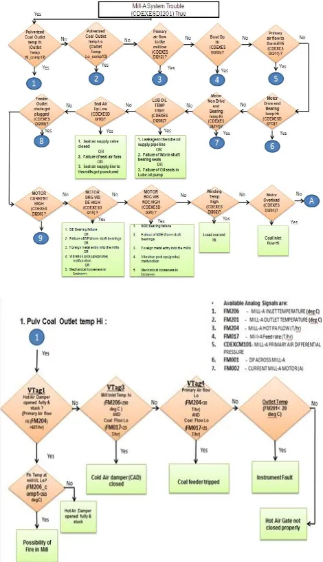
[image:7.612.323.568.131.324.2]1)Case 1: Mill-A System Trouble Alarm diagnosis - The ‗goal driven‘ flow logic of inference from the critical alarm -‗Mill-A System Trouble‘ to the root cause ‗Coal feeder tripped‘ is shown in the fault tree diagram and then executed in iRESS and results are verified
.
[image:7.612.49.284.211.619.2]Figure 7: Fault Tress For ‘Mill-A System Trouble ‘Critical Alarm
Figure 8. : Iress Online Mode Inference Results For ‘Mill –A System Trouble’ Critical Alarm
In this implementation, the KB has been built with Metarule, Rules and Frames for Mill-A System Trouble alarm diagnosis. Knowledge Base was built for diagnosis of Coal Mill System Trouble (CDEXESDI201) alarm. 27 signals (Tags) have been configured (20 Digital (DI) and 7 Analog (AI) signals) in iRESS and the same is also logged in Historian database (iDLog). The Plant data is received in iRESS by OPC interface via iROSE SCADA software. Only critical alarms will be diagnosed. For each critical alarm, one metarule should be configured for reducing the rule search. Thus metarules increases the efficiency of the inference engine by speeding the rule search. In this
implementation Coal Mill System Trouble
International Journal of Emerging Technology and Advanced Engineering
Website: www.ijetae.com (ISSN 2250-2459,ISO 9001:2008 Certified Journal, Volume 4, Issue 9, September 2014)
588
[image:8.612.330.557.132.273.2]The Inference Manager then searches through the rules and frames for finding the sub cause of the alarm. Here the Pulverized Coal Outlet Temp value was high which was the first condition of the metarule. The Inference manager then checks the condition of rule that contains the Pulverized Coal Outlet Temp as its action part. The third condition of the rule (this condition tag was configured as frame) was satisfied and its parameter description -Coal feeder tripped was displayed as root cause of the Mill-A System Trouble alarm. Action to be taken when the root cause obtained, was shown as Operator Guidance. Flow Chart is shown in Figure 7.Report for the inferenced alarms are available from Case Sheet Log menu option as shown in Figure 9.
Figure 9.:CASE SHEET LOG
For each critical alarm, one HMI frame was configured with all the subcases .For Mill-A system trouble alarm, the configured HMI is as shown in the Figure 10. Here the root cause of the alarm is Pulverized Coal outlet temp HI which is highlighted in red color. On clicking ‗Flow Chart‘ button, the corresponding sub Frame with LED indication for Alarm will be shown as in Figure 11.
[image:8.612.49.296.290.508.2]Figure 10. HMI FRAME FOR ‘Mill A System Trouble’ ALARM
Figure 11. Sub Frame With LED Indication For ALARM
2)Case 2: Online mode running of Inferencing was tested by creating the actual field Alarm with the help of TTPS engineers as given below:
[image:8.612.332.558.297.512.2]International Journal of Emerging Technology and Advanced Engineering
Website: www.ijetae.com (ISSN 2250-2459,ISO 9001:2008 Certified Journal, Volume 4, Issue 9, September 2014)
589
In iRESS software, Mill-A System Trouble was indicated as alarm and Cold Air Damper Open was indicated as the root cause of the alarm, which was correct as per the flow chart and was verified by plant engineers.
This alarm, its main cause and sub cause conditions were
[image:9.612.59.267.294.423.2]indicated in HMI frames also by LED blinking. The root cause inferred by iRESS is Hot Air Damper of Mill-A Closed OR Moisture in Coal high OR Mill Outlet Temp Sensor fail OR FW Heater Out of service as shown in Figure 13. This case was as per the flow chart and was verified by plant Engineers. The KB can be extended for other Mills of the plant also. So that the system can do alarm diagnosis for the entire plant.
Figure 12. FAULT TREE FOR ‘Mill-A System Trouble’ CRITICAL ALARM
Figure 13: iRESS ONLINE MODE INFERENCE RESULTS FOR ‘Mill –A System Trouble’ CRITICAL ALARM.
Key Benefits of using the iRESS based fault diagnosis system are the plant down time is reduced since Alarms/faults are diagnosed in real time and better operator guidance accelerates restoration of normal conditions. It also provides ability to monitor process parameters independently.
REFERENCES
[1] Kit Po Wong, ―Artificial Intelligence and Neural Network Applications in Power Systems‖, IEE 2nd International Conference on Advances in Power System Control, Operation and Management, December 1993.
[2] C. Pimpa, and S.Premrudeepreechacharn, ‖Voltage Control In Power System Using Expert System Based On SCADA System ‖, IEEE, 2002.
[3] Heinrich Kern and Medjid Fathi-Torbeghan, ―Concept for Combining features of Real-Time and Expert Systems for On-line Plant Diagnosis‖, IEEE, 1990.
[4] Yuan-Yih Hsu and Chung-Ching Su, ―A Rule Based Expert System for Steady-State Stability Analysis‖ ,IEEE Transactions on Power Systems, Vol. 6,No. 2,1991.
[5] Faguo Zhou, Bingru Yang, Linna Li, Zhuo Chen, ―Overview of the New Types of Intelligent Decision Support System‖, The 3rd Intetnational Conference on Innovative Computing Information and Control IEEE, 2008
[6] Joel D. Riedesel, ―An Object Oriented Model for Expert System Shell Design‖, IEEE, 1990.
[7] LCinque, M.Crispoldi and S.Levialdi, ―Use of Meta-knowledge in an Expert System: a real case application‖, International Workshop on Industrial Applications of machine Intelligence and Vision, IEEE 1989.
[8] Chuleerat Rattanaprateep and Suphamit Chittayasothorn, ―A Frame-based Object Relational Expert Database System ‖, IEEE, 2007 [9] A. Sadeghian and J. D. Lavers, ―Implementation of
Knowledge-Based System for Iron Core Inductor Design‖,IEEE Transactions On Magnetics, Vol. 40, No. 6, November 2004
[10] Osamu Iida Masahiko Urakami and Tadaaki Iwamura, ―Applications and Evaluation of AI Technology in the Steel Industry‖, IEEE, 1993.
[11] Abhir Raj Metkar, Latha B. Kaimal, Rakesh G, ―Self Learning Expert System‖, AISC 2013
[image:9.612.50.287.458.630.2]