Design and control of a novel variable
stiffness soft arm
Hao, L, Chaoqun, X, Giannaccini, ME, Cheng, H, Zhang, Y, NeftiMeziani, S and
Davis, ST
http://dx.doi.org/10.1080/01691864.2018.1476179
Title
Design and control of a novel variable stiffness soft arm
Authors
Hao, L, Chaoqun, X, Giannaccini, ME, Cheng, H, Zhang, Y, Nefti
Meziani, S and Davis, ST
Type
Article
URL
This version is available at: http://usir.salford.ac.uk/id/eprint/46856/
Published Date
2018
USIR is a digital collection of the research output of the University of Salford. Where copyright
permits, full text material held in the repository is made freely available online and can be read,
downloaded and copied for noncommercial private study or research purposes. Please check the
manuscript for any further copyright restrictions.
Design and Control of a Novel Variable Stiffness Soft arm
Lina Hao
1,4Chaoqun Xiang
1,2,3M.E. Giannaccini
2,3Hongtai Cheng
1Ying Zhang
1S. Nefti-Meziani
2Steven Davis
2(1. School of Mechanical Engineering & Automation, Northeastern University, Shenyang 110819, China 2. Centre for Autonomous Systems and Advanced Robotics, University of Salford, Salford, United Kingdom 3. Soft Robotics Group, Bristol Robotics Laboratory, University of Bristol, Bristol, United Kingdom 4. [email protected])
Abstract: Soft robot arms possess such characteristics as light weight, simple structure and good adaptability to the environment, among others. On the other hand, robust control of soft robot arms presents many difficulties. Based on these reasons, this paper presents a novel design and modelling of a fuzzy active disturbance rejection control (FADRC) controller for a soft PAM arm. The soft arm comprises three contractile and one extensor PAMs, which can vary its stiffness independently of its position in space. Force analysis for the soft arm is conducted, and stiffness model of the arm is established based on the relational model of contractile and extensor PAM. The accuracy of stiffness model for the soft arm was verified through experiments. Associated to this, a controller based on the fuzzy adaptive theory and ADRC, FADRC, has been designed to control the arm. The fuzzy adaptive theory is used to adjust the parameters of the ADRC, the control algorithm has the ability to control stiffness and position of the soft arm. In this paper, FADRC was further verified through comparative experiments on the soft arm. This paper reinforces the hypothesis that FADRC control, as an algorithm, indeed possesses good robustness and adaptive abilities.
Key words: soft robot, variable stiffness, PAM, stiffness modelling, FADRC
Introduction
The rapid development of robot technology, entails that rigid robots enjoy a very wide range of applications. Conventional robots essentially mimic mammals, which possesses rigid links[1]. Due to the limited degrees of freedom (DOF) and main component materials of rigid robot, they also suffer from some disadvantages such as high cost, heavy weight and poor compatibility with unstructured environments. Soft robots enjoy low cost, light weight, softness, simple structure among other advantages. Soft and compliant robots are particularly apt for unstructured environments due to their flexibility, versatility and claims to safety.
In general, actuation strategies for soft robots are chosen in order not to interfere with the compliance of their body. For example, the actuation can be achieved pneumatically or with cables and thin shape memory alloy wires[2]. For instance, OctArm[3] and continuum manipulators[1] are examples of pneumatic soft arms. The design principle of the OctArm is bioinspired. It imitates hydrostatic skeletons such as the elephant trunk and the octopus tentacles. These impressive animal structures are completely boneless, but nevertheless can produce bending, contraction, and elongation movements [4]. This kind of robot possesses the advantage of light weight, flexibility and increased claims to safety compared to conventional robots. Chen, developed one section of a pneumatic continuum robot (Clobot)[5] that is made of silicone rubber. It can bend 120° under 0.2mbar. Another pneumatic and continuum arm, the Bionic Handling Assistant (BHA) [6], was designed by the Festo Company. . Although the resultant soft robots are lightweight and flexible, their bodies still retain much rigidity, which is used to maintain their shapes. Hence their stiffness does not change with change in position and load.
problem unless high-bulk modulus fluids are used in underwater soft robots [19]. To avoid excessive weight, this paper proposes a variable stiffness soft arm driven by PAMs. A PAM is a two layered system consisting of an inner elastomeric bladder surrounded by an external woven braided shell. The wind angle of the braided shell, φ, is of critical importance. If φ > 54°44’, then the PAM is an expanding muscle and the muscle elongates when it is pressurized. But if φ < 54°44’, then the PAM is a contractor muscle[3, 20] and the muscle contracts when pressurized. Soft robots made of PAMs comply with the requirements for an intrinsically safer physical human–robot interaction.
Michael B. Pritts, and et al. have also developed a continuum robot driven by contractile and one extensor PAMs, but the stiffness of the arm can not be varied independently from their end-effector position in space[21]. Koichi Suzumori, and et al. also have develop a continuum robot driven by contractile and one extensor PAMs, however the structure of arm is one contractile PAM at the center of the arm and the five extensor PAMs are equidistant from the center of the arm, under the same size, normally the output force of contractile PAM is larger extensor PAM, so the structure will limit the output force of the arm[22].
PAMs possesses very strong nonlinearity, which is not convenient for control. Active disturbance rejection control (ADRC) is proposed by Han[23], and possesses properties of active disturbance rejection which estimate disturbance and compensation in real time. Furthermore an ADRC controller does not need an accurate model system, and possesses the properties of active disturbance rejection, which refers to the function of estimating disturbance and compensation in real time[23, 24]. ADRC has been employed in the domain of nonlinear control system of robot driven by PAMs, such as a PAM mechanism to achieve angle tracking precisely under varying load conditions[25], positioning control of the one-DOF manipulator driven by pneumatic artificial muscles[26], and trajectory tracking and decoupling for a two-joint system driven by PAMs[27]. However, too many parameters of ADRC need to be adjusted, which is not convenient to use. In the reference [28], [29] and [30],a fuzzy adaptive theory is used to adjust the parameters of ADRC, which achieved a good result. Thus Fuzzy adaptive theory is employed to adjust the parameters of ADRC in the paper.
In this paper, a novel soft arm made of one expansive PAM and three contractile PAMs, described in [31] and that uses the principle of decoupled variable stiffness and positioning is utilised. Due to the ability to vary its stiffness, when the arm comes across a disturbance force, it will increase stiffness. This will decrease deformation and increase its control accuracy and robustness. If a human collides with the arm, the arm can decrease its stiffness and become softer and safer for the human. Both its stiffness model and kinematics model have been established based on the working theory of the arm. In this paper, the FADRC controller is proposed to take advantage of its adaptive properties as described within the fuzzy adaptive theory. Verification of the design controller was completed in experiments based on the variable stiffness of the soft arm. The experimental results demonstrated better accuracy and stability than would be obtained from testing results with the traditional PID controller.
The paper is structured as follows: in the first section, the structure and working principle of the arm are introduced. In the second and third sections, the kinematics model and the stiffness model of the arm are established, respectively. In the following sections, FADRC is proposed, and position and stiffness of the arm are controlled through this controller. General conclusions relating to the paper are formulated in Section seven.
1
Description of variable stiffness soft arm
1.1 Design concept
Fig.1 Schematics of the arm
Tab.1 The geometric parameters of arm and PAMs
Length of the arm(no pressurized)
/mm
Expansive PAM Contractile PAM
Initial length
/mm diameter /mmInitial Initial braid angle/°
Maximum inflation pressure
/bar
Initial length
/mm diameter /mmInitial Initial braid angle/°
Maximum inflation pressure
/bar
625 625 40 55 2.5 625 20 32 2.5
1.2 Working principle
Due to the symmetry of the structure and the fact that each PAM can be inflated with a different air pressure the arm can achieve elongation that consequently causes bending. To be of use in different tasks, the stiffness of a PAM can be adjusted independently of its length.
When the arm reaches a certain position, through adjusting the inflating pressure of the expansive PAM and the contractile PAMs simultaneously, the stiffness can be adjusted. The principle of variable stiffness applied for the arm is shown in figure 2 in which the length of the arm remains the same. On the left hand side of Figure 2(a), the expansive PAM is inflated and the other contractile PAMs are not inflated. The status of this arm is such that it is working at lower stiffness. On the right hand side of Figure 2(a) all the four PAMs are inflated at the same time. This arm is working at higher stiffness. The working principle of the arm is reminiscent of that of a tug-of-war, shown in figure 2(b). This principle is also applied when the arm is bending. Both for straight and bent configurations, the stiffness of the arm can be changed by adjusting the inflating pressure of three contractile PAMs and that of the singular expansive PAM.
Fea
Fcb3
Fcb1
Fcb2
Feb
Stiffness Expansive PAM
Contractile PAMs
(a) Arm (b) Tug-of-war Fig.2 The variable stiffness principle of the soft arm
2
Kinematics model
The approach to the design of kinematics models for soft robots is quite different from the approaches followed for traditional rigid robots. This is due to the fact that fixed link length and joint variables are concepts not applicable to soft robots. In order to predict the behavior of the manipulator, it was necessary to analyze the kinematics of the soft arm as well as the displacement performance of each of the three PAMs. In reference [33] and [34], the authors defined four properties which would describe the position of the free end of the PAMs relative to the base. The radius of the curve formed was defined as λ. ϕ was used to describe the angular displacement between the two ends of the element. L was the length of the arc formed and θ was the angle the end of the element pointed relative to the base coordinate frame.
The resultant soft arm in the o-xyz coordinates is shown in figure 3. It can be observed that on two ends of the arm there are two round plates. o2 and o1 are in the center of the top plate and the bottom plate, respectively. A1, A2 and A3 stand for the points that the three contractile PAMs are fixed at the top plate. B1, B2 and B3 stand for the points that the three contractile PAMs are fixed at the bottom plate. o2-xyz is established on the top plate and o2 is the center of the top
Expansive PAM Ties
plate. A1 is on the axis of o2x and z is vertically upward on the top plate. Without pressure, the four PAMs are at the same length. So the length is 625mm.
c
o
x
z
2o
1
o
1A
y
2
A
3
A
1 B 3
B
2
B
θ
Φ
L
Fig.3 Kinematics of the soft arm
Godage et al.[35]
0 0 1 2 3
2 2 2
1 2 3 1 2 2 3 1 3
[3( ) ]
2
L l l l l r
l l l l l l l l l
(1)
2 2 2
1 2 3 1 2 2 3 1 3
2
3
l
l
l
l l
l l
l l
r
(2)
1 3 2
2 3 1
3( )
tan [ ]
2
l l
l l l
(3)
0 0 1
2
3
0 0 03
3
3
L
l
l t
l
t
l t
L
l
l
t
(4)
Equations(1), (2), (3) and (4) are therefore, the kinematics model of the soft arm. The kinematics model can be used to determine the lengths L1, L2 and L3 in the stiffness model described in the next section.
3
Stiffness model
3.1 Experimental identification of the mechanical model of PAM
According to literature review [36], a PAM can be treated like a spring and hence Hooke’s law can be applied to it. The output force for the contractile PAM and the expansive PAM can thus be expressed as follows:
( ) ( )
ci ci ci i ci ci
F K P L L P
(5)
( ) ( )
e e e e e
F K P L P L
(6)
where, Pci(i=1,2,3) and Pe are the inflation pressures of contractile PAMs and expansive PAM respectively, (unit: bar).
Kci(Pci)(i=1,2,3) and Ke(Pe) are the stiffness in N/m for the contractile PAMs and the expansive PAM, respectively.
Lci(Pci)(i=1,2,3) and Le(Pe) are the lengths in m for the contractile PAMs and the expansive PAM, respectively. Kci(Pci),
Ke(Pe), Lci(Pci) and Le(Pe) are identified through the following experiments. L is the actual length of expansive PAM.
3.1.1 Experimental set up
Cylinder
Displacement sensor
PAM
PC
Support
Air source triplet
Pressure sensor
Arduino SPCU
Air compressor
Fig.4 Schematic diagram of the experimental measurement system for pneumatic artificial muscle
2
2
4
g
F
D
d
P
(7)
where Fg is the output force of cylinder which provides load for the PAM. D is the diameter of the piston, d is the diameter of piston rod and P is the pressure of the cylinder.
3.1.2 Model identification
Firstly the test rig in figure 5 is used to test the length of the PAM under no-load. The inflation pressure of cylinder is set at 0bar, then the inflation pressures of the cylinder are set as from 0bar to 2.5bar in intervals of 0.2bar. The experiment is performed under quasi-static conditions. MATLAB software is used to fit the model. The lengths of the contractile PAMs and the expansive PAM can be expressed as follows,
3 2
1 2 3 4 2.5
ci ci ci ci ci
L a P a P a P a P
(8)
4 3 2
1 2 3 4 5 2.5
e e e e e e
L b P b P b P b P b P
(9)
where, a1=0.0212, a2=-0.0704, a3=-0.00689, a4=0.62844. b1=-0.03893, b2=0.2421, b3=-0.527, b4=0.47, b5=0.625.
Lci(Pci)(i=1,2,3) and Le(Pe) are the lengths of the contractile PAMs and the expansive PAM in m, respectively.
Secondly, the test rig of Figure 5 is used to test the stiffness of the PAM. The inflation pressures of the PAMs are regulated through the air source triplet, which in this instance, is set from 0bar to 2.5bar at intervals of 0.5bar. Then, the setting of the inflation pressure of cylinder is changed to between 0bar and 3bar, at an interval of 0.2bar so that the load is from 0N to 212N. MATLAB software is then used again to fit the stiffness of the PAM. The stiffness of the contractile PAMs and the expansive PAM can thus be expressed as follows,
3 2
106
596
1275
275.64
ci ci ci ci
K
P
P
P
(10)
3 2
18.9
1.9048
374.48
139.4
e e e e
K
P
P
P
(11)
where, Kci(Pci)(i=1,2,3) and Ke(Pe) are the stiffness of the three contractile PAMs and the expansive PAM in m, respectively. According to the equations of (5) and (6), PAMs still possesses some stiffness under no inflation pressure. This stiffness characteristics largely depends on the material characteristics of elastic tube and external woven braided shell.
3.2 Stiffness model of the arm
While the soft arm is in the fixed bent position shown in Figure 5, the arm is under force balance. The forces generated by both contractor and extensor PAMs are perpendicular to the bottom mounting plate. Force analysis is conducted on the arm, and the force analysis is in Figure 6, because the output force direction of PAM muscles are inverse, the cross symbol is used to express the output force of contractile PAMs, and the dot symbol is used to express the output force of expansive PAM. In order to determine the axis stiffness, there is force a F applied on the soft arm, which causes the changing of the length, according to force balance and moment balance, then the forces can be expressed as follows,
1 2 3
c c c e
F
F
F
F
F
(12)
1 2 3
2
c c c
F
r
F
r
F
r
(13)
1 1 2 2
c c
F
l
F
l
(14)
distances from Fc1, Fc2 tothe axis of y1 are l1, l2 respectively. Then the equations can be simplified as follows,
1 2 3
3
e
c c c
F
F
F
F
F
(15)
x z 2 o 1 o 1 A y 2 A 3 A 1 B 3 B 2 B
1 F e F 3 F 2 F F C O F L Fe,F Fc1 x1 y1 Fc2 Fc3(a) Visualisation of orientation of forces of the arm (b) Location of point of force application on the bottom plate Fig.5 Geometric and force analysis
If (5) and (6) are substituted it into (15) respectively, then it can be expressed as follows,
1 1 1
1
(
)
(
)
(
)
3
e e e e
c c c
K P
L P
L
F
L
L
P
K
(16)
2 2 2
2
(
)
(
)
(
)
3
e e e e
c c c
K P
L P
L
F
L
L
P
K
(17)
3 3 3
3
(
)
(
)
(
)
3
e e e e
c c c
K P
L P
L
F
L
L
P
K
(18)
If (16), (17) and (18) are substituted into (15), then L1, L2 and L3 canbe eliminated. So, it can be expressed as follows,
1 2 3
9
LA
K LB
eK L
e e3 (
A L
cL
cL
c)
F
B
(19)
where,
1 2 3 c c c
A
K K K
B(K Kc1 c2K Kc1 c3K Kc3 c2) Under different inflation pressure, the stiffness of the arm can be expressed as follows,
Arm
dF
K
dL
(20)
If a derivative of (20) is taken, then stiffness of arm can be shown as follows,
1 2 3 1 2 2 3 1 3
1 2 2 3 1 3
9
c c c e(
c c c c c c)
Arm
c c c c c c
K K K
K K K
K K
K K
K
K K
K K
K K
(21)
4
Experimental Verification of stiffness model
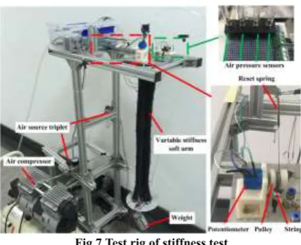
4.1 Test rig
In order to verify the accuracy of the stiffness model of the soft arm, a schematic diagram of the stiffness tests and the figure of the test rig are shown in Figure 6 and Figure 7 respectively.
Air compressor Air source triplet Contractile PAM1 Contractile PAM2 Contractile PAM3 Expansive PAM Pressure sensor Arduino L
Pe, Pc1,
Pc1, Pc1 Air source
triplet
Potentiometer
PC
Fig.7 Test rig of stiffness test
Figure 7 shows the test rig, which includes an air compressor, air source triplet, 1kg weight, four air pressure sensors, reset spring, potentiometer, pulley, and string. In the experiment, the air compressor is used for air supply for the PAM. The air source triplet is used to regulate the inflation pressure of the PAM. The pressure sensors are used to read the inflation pressure of the PAM. One end of the string is connected with the reset spring. The other end is connected with the bottom plate of soft arm and is further connected on the expansive PAM by nylon ties. When the arm starts to move, the length of the soft arm will change. Then pulley will start to turn and the resistance will also change. The changes in resistance can be calculated by measuring the length of the soft arm. The Arduino microcontroller will collect the data from the potentiometer in real time. The weight is used to provide the load for the arm.
4.2 Experimental Test
In the experiment, before loading, the inflation pressure of the four PAMs is selected so the arm keeps the length of 610mm. Firstly, the expansive PAM is inflated and the arm will elongate as a result. Then the inflation pressure of the three contractile PAMs is regulated and the length of the arm is decreased back to 610mm. The expansive PAM is set from 0bar to 2.50bar with intervals of 0.50bar. The three contractile PAMs are set at 0.80bar, 0.90bar, 1bar, 1.20bar, 1.40bar and 1.45bar, respectively. Secondly, 1kg weight is loaded on the bottom end of the soft arm and the length variation is collected through the Arduino. These experiments are repeated three times and the mean values are calculated. The test results are shown in figure 8.
[image:8.595.131.463.486.763.2]From figure 8, it can be observed that the experimental results and the results of the theoretical stiffness model both possess the same trend. The mean error is 4.09% and the maximum error is 5.56%.
[image:9.595.110.481.234.512.2]In order to test the stiffness of the arm in a bending position, the pressure of two contractile PAMs are set at equal pressure, while the pressure of the third PAM is set differently, the arm will be bent. The length of the arm is also adjusted at 610mm. Firstly, the expansive PAM is inflated and the arm will elongate as a result. Then the inflation pressure of the three contractile PAMs is regulated (the pressure of the two of the PAMs are adjusted equally, and the pressure of the third PAM is adjusted differently from the other two.) and the length of the arm is decreased back to 610mm. The expansive PAM is set from 0bar to 2.50bar with intervals of 0.50bar. The two contractile PAMs are set at 0.60bar, 0.80bar, 0.85bar, 0.90bar, 1.1bar and 1.2bar, respectively. The third PAM is set at 0.90bar, 1.20bar, 1.30bar, 1.33bar, 1. 60bar and 1.65bar, respectively. A dynamometer is applied to the center of the bottom plate, then the length variation and the data from the dynamometer are collected. Then the stiffness of the arm are calculated, and the results are shown in figure 9.
Fig. 9 Comparison schematics of experiment value and theoretical value in a bending position
From figure 9, it can be observed that in the stiffness test of the arm in a bending position the experimental results and the results of the theoretical stiffness model also both possess the same trend. The mean error is 4.30% and the maximum error is 6.33%. The reason for the error is that the theoretical stiffness model does not take friction and the influence of the ties into account.
5
Stiffness and position control
5.1 Auto/Active Disturbances Rejection Controller (ADRC)
An ADRC controller includes a Tracking Differentiator (TD), an Extended State Observer (ESO) and a Nonlinear State Error Feedback (NLSEF). The structure diagram of a second order ADRC system is shown in figure 10.
TD NLSEF Plant
v
ESO
1
/b
b1
v
2 v
0
u
u y
1
e
1 z z2
3
z
2
[image:9.595.177.417.677.761.2]e
Fig. 10 The structure diagram of a second order ADRC system
shown in formula (23), 1 2 2 x x x u &
&
(22)
1 1 2
2 2 1 2 0
1
1
1 1 2 01
2 2 3 02
3 3 03 1
( 1) ( ) * ( )
( 1) ( ) * ( ( ) ( ), , , )
( ) ( )
( , 0.5, )
( , 0.25, )
( 1) ( ) * ( ( ) )
( 1) ( ) * ( ( ) )
( 1) ( ) * ( )
v t v t T v t
v t v t T fhan v t v t v r h
e z t y t
fe fal e h
fe fal e h
z t z t h z t e
z t z t h z t fe u
z t z t h fe
TD: ESO:
1 1 1
2 2 2
0 1 1 1 2 2 1
0 3
( ) ( )
( ) ( )
( , , ) ( , , )
( ) ( )
e v t z t
e v t z t
u fhan e r h fhan e r h
t u z t
NLSEF:
u:u =
(23)
where, (1 )*
,
( , , )
*
( ),
a ae d
e
d
fal e a d
e
sign e
e
d
(24)
The computational method of fhan(x1, x2, r, h) is shown as follows,
0 1 2 0 2 0 0 2 0
(
)
( ),
2
,
( ),
,
d
rh
d
hd
y
x
hx
a
d
x
sign y
y
d
a
y
x
y
d
h
rsign a
a
d
fhan
a
r
a
d
d
(25)
TD: v(t) is the input signal, v1(t) is the tracking signal of v(t), T is the sample time, a is non-linear factor, h is filter factor and R is velocity factor.
ESO: y(t) is the output of the system, z1(t) is the tracking signal of y(t), z2(t) is the differential signaling of z1(t), z3(t) is the disturbance signal of the system, e is the error signal, β01, β02, and β03 is the gain of error correction, and the algorithm of fal(•) is in (24).
NLSEF: e1 and e2 are error and differential signal respectively, β1 and β2 are error gain and differential gain.
5.2 FADRC
Fuzziness
Data base
decision logic defuzzify object d/dt
e
y
Fig.11 Block Diagram of Fuzzy Control System
From figure 11, the ESO fuzzy variables are e, e′, Δβ
01, Δβ02 and Δβ03. The ESO NLSEF fuzzy variables are e1, e2, Δβ1 and Δβ2. The membership function of e, e′, e1and e2 is the gaumssf. The membership function of Δβ01, Δβ02, Δβ03, Δβ1 and Δβ2 is trimf. The Mamdani method is selected for fuzzy deduction in which the method of defuzzifying is the weighted average. For (Δβ01, Δβ02, Δβ03, Δβ1, Δβ2), the fuzzy rule is given in table 2.
Tab.2 Δβ01, Δβ02, Δβ03, Δβ1 and Δβ2 fuzzy rule table
e′/e1 e/e2
NB NM NS ZO PS PM PB
NB PB PB PM PM PM ZO ZO
NM PB PB PM PS PS ZO NS
NS PM PM PM PS PS NS NS
ZO PM PM PS ZO NS NM NM
PS PS PS ZO NS NS NM NM
PM PS ZO NS NM NM NM NB
PB ZO ZO NM NM NM NB NB
According to the fuzzy rule table, the membership function and fuzzy deduction, Δβ01, Δβ02, Δβ03, Δβ1 and Δβ2 can be checked out. The they can be substituted into the following function:
01 01 01
02 02 02
03 03 03
1 1 1
2 2 2
=
=
=
=
=
(26)
where, β′
01, β′02, β′03, β′1 and β′2 are the initial values. According to equation (21), β01, β02, β03, β1, and β2, can also be
calculated. Then, FADRC can be designed. Based on the reference [28], the schematic of FADRC is shown in figure 12.
TD NLSEF Plant
v
ESO
1
/b
b1
v
2
v
0
u
u y
1
zz2
3
z
Fuzzy deduction
Fuzzy deductio
n
1
e
2
e
1, 2
01, 02, 03
e
Fig.12 Schematic of FADRC
6
Experimental verification of FADRC control
6.1 Control system design of Soft arm of FADRC control
(k)
Soft arm
(Lc1)
+
-(Lc1)
(Lc2)
(Lc3)
+
-+
-+
-
ADRCFuzzyInverse Kinematics
model
( pc2)
( pc3)
( pe)
(Lc2)
(Lc3)
Fuzzy ADRC
Fuzzy ADRC Fuzzy
ADRC
( , , )
(Lc1)( pc1)
(
Δ
k)
Stiffness model
Stiffness model
(
K
)
(Lc2)
(Lc3)
(u)
Fig.13 Control schematic diagram of position and stiffness control system
6.2 Experimental platform setup
The test rig of figure 7 is changed to the rig shown in figure 14. The three potentiometers shown in Figure 14 are used to measure the length of the three contractile PAMs. The four PAMs are controlled through a MATRIX solenoid valve. The Arduino is used to collect the data from the pressure sensors and the potentiometers and then send the data to MATLAB.
Fig.14 Test rig of control system
Solenoid valve
Potentiometers Arduino
Variable stiffness soft
arm Drive circuit
PC
Air pressure sensors
L=(L1, L2, L3)T
P=(Pe, Pc1, Pc1, Pc1)T
Fig.15 The principle diagram of control test
6.3 Experiments
To investigate the control effect of the FADRC controller, a PID controller and FADRC controller were applied to control the soft arm. Using the test rig of Figure 14, experiments on the soft arm were carried out under no-load and 500g load, respectively.
6.3.1 Stiffness Control Experiments
the arm is controlled to track a square signal. The goal of this experiments is to test the stiffness controllability of this arm. A step signal with an amplitude of 590mm, 610mm and 610mm was applied as reference signal for the three PAMs, respectively. The three contractile PAMs have different lengths, thus the arm will be bent. The pressure of the expansive PAM is controlled as an intermediate variable of the stiffness of the arm. The reference signal for stiffness is a square signal of 3000N/m-3800N/m in amplitude, with a period of 30s. The control parameters of the FADRC controller for the contractile PAMs are r=2000, h=0.001, T=0.001, β01=1, β02=0.33, β03=1/27, β1=90, β2=150, a1=0.8, b=1.5, d=0.01. The control parameters of FADRC for the expansive PAMs are r=1000, h=0.001, T=0.001, β01=1, β02=0.33, β03=1/27, β1=0.9,
β2=0.00003, a1=0.4, a2=1.1, b=1.4, d=0.01.
The control parameters of PID for the three contractile PAMs are P=4, I=0.3, and D=0. The control parameters of PID for the expansive PAM are P=0.16, I=0, and D=0. The control results of position and stiffness for the soft arm under no load and 500g load are shown in figure 16 and figure 17.
0 10 20 30 40 50 60
580 590 600 610 620 630 640 t(s) l1 (m m ) Target PID FADRC
40 45 50 55
588 590 592 594 t(s) l1 (m m ) Target PID FADRC
0 10 20 30 40 50 60 -50 -40 -30 -20 -10 0 10 t(s) E rr o r( m m ) FADRC PID 40 50 60
-2 0 2 t(s) E rr o r( m m ) FADRC PID
(a1) (a2)
0 10 20 30 40 50 60
605 610 615 620 625 630 635 640 t(s) l2 (m m ) Target PID FADRC
35 40 45 50 55 608 609 610 611 612 613 t(s) l2 (m m ) Target PID FADRC
0 10 20 30 40 50 60 -30 -25 -20 -15 -10 -5 0 5 t(s) E rr o r( m m ) FADRC PID
35 40 45 50 55 -4 -2 0 2 t(s) E rr o r( m m ) FADRC PID
(b1) (b2)
0 10 20 30 40 50 60 605 610 615 620 625 630 635 640 t(s) l3 (m m ) Target PID FADRC
20 40 60
608 609 610 611 612 613 t(s) l3 (m m ) Target PID FADRC
0 20 40 60
-30 -25 -20 -15 -10 -5 0 5 t(s) E rr o r( m m ) FADRC PID
20 30 40 50
-2 0 2 t(s) E rr o r( m m ) FADRC PID
0 10 20 30 40 50 60 0 1000 2000 3000 4000 5000 t(s) K (N /m ) Target PID FADRC
(d1) (d2)
Fig.16 Under no load, experiment results of stiffness and position control of soft arm. (a1), (b1) and (c1) stand for the length of three contractile PAMs respectively, and (d1) stands for the stiffness of the soft arm. (a2), (b2), (c2) and (d2) are the corresponding error of (a1), (b1), (c1) and (d1).
0 10 20 30 40 50 60
580 590 600 610 620 630 640 650 t(s) l1 (m m ) Target PID FADRC
40 50 60
588 590 592 594 596 t(s) l1 (m m ) Target PID FADRC
0 20 40 60
-60 -50 -40 -30 -20 -10 0 10 t(s) E rr o r( m m ) FADRC PID
40 45 50 55
-6 -4 -2 0 t(s) E rr o r( m m ) FADRC PID
(a1) (a2)
0 10 20 30 40 50 60
605 610 615 620 625 630 635 640 t(s) l2 (m m ) Target PID FADRC
20 40 60
606 608 610 612 t(s) l2 (m m ) Target PID FADRC
0 10 20 30 40 50 60
-30 -25 -20 -15 -10 -5 0 5 t(s) E rr o r( N /m ) FADRC PID
20 40 60
-1 0 1 2 t(s) E rr o r( N /m ) FADRC PID
(b1) (b2)
0 10 20 30 40 50 60
600 610 620 630 640 650 660 t(s) l3 (m m ) Target PID FADRC
40 50 60
608 610 612 614 t(s) l3 (m m ) Target PID FADRC
0 10 20 30 40 50 60
-50 -40 -30 -20 -10 0 10 t(s) E rr o r( s) FADRC PID
40 50 60
-4 -2 0 2 t(s) E rr o r( s) FADRC PID
(c1) (c2)
(d1) (d2)
[image:15.595.336.517.485.790.2]Fig.17 Under 500g load, experiment results of stiffness and position control of soft arm. (a1), (b1) and (c1) stand for the length of three contractile PAMs respectively, and (d1) stands for the stiffness of the soft arm. (a2), (b2), (c2) and (d2) are the corresponding error of (a1), (b1), (c1) and (d1).
Figure 16 and 17 are the control results of PID and FADRC respectively. L1, L2 and L3 stand for the length of three contractile PAMs. These two controllers can achieve the control of position and variable stiffness of the arm under no load or 500g load. The FADRC is obviously better than the traditional PID controller, because FADRC possesses a relatively lower overshoot and better accuracy. Based on figure 16(d1), the average error of PID and FADRC is 105.27N/m and 55.37N/m, respectively. Based on Figure 17(d1), the average error rate of PID and FADRC is 58.22N/m and 51.31N/m%, respectively. From the position control results of the soft arm of figure 16 and 17, FADRC is also better than the PID. The position control of maximum steady-state average error rate of PID and FADRC after 20s in figure 16 is 0.42% and 0.18%, respectively. Under 500g, the position control results of PID and FADRC in figure 17 is 0.21% and 0.17%, respectively. Under 500g, FADRC also possesses good control results, which means this controller has good adaptability.
6.3.2 Position Control Experiments
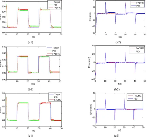
In this section, the position control of this arm was carried out. Three contractile PAMs are controlled to track a square signal, and the pressure of expansive PAM is set to 0.5bar. The goal of this experiments is to test the position controllability of this arm. The reference signal for position of L1 is a square signal of 590mm-625mm in amplitude, with a period of 20s, and the reference signal for position of L2 and L3 is a square signal of 600mm-625mm in amplitude, with a period of 20s. L1 moves more than L2 and L3 which causes the arm to bend, so the arm is bending during the experiments.
The control parameters of the FADRC and PID controller for the contractile PAMs are the same with the stiffness control experiments.The control results of position for the soft arm under no load and 500g load are shown in figure 18 and figure 19.
(a1) (a2)
0 10 20 30 40 50 60
500 1000 1500 2000 2500 3000 3500 4000 4500
t(s)
K
(N
/m
)
Target PID FADRC
0 10 20 30 40 50 60 -1500
-1000 -500 0 500 1000 1500 2000 2500
t(s)
E
rr
o
r(
m
m
)
FADRC PID
0 10 20 30 40 50 580
590 600 610 620 630 640
t(s)
l1
(m
m
)
Target PID FADRC
0 10 20 30 40 50
-60 -40 -20 0 20 40
t(s)
E
rr
o
r(
m
m
)
FADRC PID
0 10 20 30 40 50
595 600 605 610 615 620 625 630
t(s)
l2(m
m)
Target PID FADRC
0 10 20 30 40 50 -30
-20 -10 0 10 20 30
t(s)
E
rr
o
r(
m
m
)
(b1) (b2)
[image:16.595.56.525.54.202.2]
(c1) (c2)
Fig.18 Under no load, experiment results of position control of soft arm. (a1), (b1) and (c1) stand for the length of three contractile PAMs respectively. (a2), (b2), and(c2) are the corresponding error of (a1), (b1), and (c1).
(a1) (a2)
(b1) (b2)
[image:16.595.51.528.247.691.2]
(c1) (c2)
Fig.19 Under 500g load, experiment results of position control of soft arm. (a1), (b1) and (c1) stand for the length of three contractile PAMs respectively. (a2), (b2), and(c2) are the corresponding error of (a1), (b1), and (c1).
Figure 18 and 19 are the position control results of PID and FADRC respectively. Based on figure 18, the maximum average error of PID and FADRC for L1, L2 and L3 is 2.46mm and 1.75mm, respectively. Based on Figure 19, the maximum average error rate of PID and FADRC for L1, L2 and L3 is 3.32mm and 2.85mm, respectively. From the position control results of the soft arm of figure 18 and 19, the soft arm possesses a relative good position controllability, and the feasibility of FADRC on the position control of soft arm is proved again.
0 10 20 30 40 50
595 600 605 610 615 620 625 630
t(s)
l3(m
m)
Target PID FADRC
0 10 20 30 40 50
-30 -20 -10 0 10 20 30
t(s)
l3
(m
m
)
FADRC PID
0 10 20 30 40 50
580 590 600 610 620 630 640
t(s)
l1(m
m)
Target PID FADRC
0 10 20 30 40 50
-60 -40 -20 0 20 40
t(s)
Err
or(
mm
)
FADRC PID
0 10 20 30 40 50
590 600 610 620 630 640
t(s)
l2(m
m)
Target PID FADRC
0 10 20 30 40 50 -40
-20 0 20 40
t(s)
Err
or(
mm
)
FADRC PID
0 10 20 30 40 50
590 600 610 620 630 640
t(s)
l3(m
m)
Target PID FADRC
0 10 20 30 40 50 -40
-20 0 20 40
t(s)
Err
or(
mm
)
7
Conclusion
The innovation point of this new arm’s design resides in allowing the variation of the arm’s stiffness independently from its position in space. Compliance for the arm is desirable for tasks that require more flexibility and adaptability to the environment, and high stiffness characteristic is desirable for tasks that require for high position accuracy application. As argued in the introduction, light weight and soft is a very important characteristic for robot to be inherently safe for physical human-robot interaction. Thus, all these aspects are considered in the design of robot arm structures in the literature, however, in no other case the arm design combines a completely soft physical structure.
The pneumatically actuated soft arm possesses inherent light weight of and the ability to vary its stiffness independently of its length, and the control of a novel soft arm composed of three contractile PAMs and one expansive PAM which can vary its stiffness independent of its position in space, has been successfully presented. The stiffness models has been established in the paper. The paper demonstrates that the experimental data and data from the theoretical model both possess the same trend. When the arm is straight, there is a mean error of 4.09% and a maximum error of 5.46%. After bending, the mean error is 4.30% , while the maximum error rate is 6.33%. A novel FADRC control method was proposed to implement the position and the variable stiffness control of the soft arm under no load and when carrying 500g load, respectively. As compared to the PID controller, experiments demonstrated that the FADRC controller was much more effective in controlling the position and the stiffness. Future work will target a more precise stiffness model and kinematics model, and replicate the link described in this paper to allow the creation, model and control of a multi-link manipulator.
ACKNOWLEDGEMENTS
This work was particularly supported by the National High Technology Research, Development Program of China (863 program) under Grant No. 2015AA042302, NSFC under grant 61573093, and the Fundamental Research Funds for the Central Universities of China under grant N150308001. The authors would also like to sincerely thank the reviewers and editors for their very pertinent remarks that helped this article become clearer and more precise.
Reference
[1]. Rongjie, K.,David, T. B.,Tianjiang, Z., etc. Design, modeling and control of a pneumatically actuated manipulator inspired by biological continuum structures[J]. Bioinspiration & Biomimetics, 2013, 8 (3): 036008. [2]. Laschi, C.,Cianchetti, M.,Mazzolai, B., etc. Soft Robot Arm Inspired by the Octopus[J]. Advanced Robotics, 2012/01/01, 2012, 26 (7): 709-727.
[3]. McMahan, W.,Chitrakaran, V.,Csencsits, M., etc. Field trials and testing of the OctArm continuum manipulator[A]. In Proceedings 2006 IEEE International Conference on Robotics and Automation, 2006. ICRA 2006.[C], 15-19 May 2006, 2006; 2336-2341.
[4]. !!! INVALID CITATION !!! [4, 5].
[5]. Chen, G.,Pham, M. T.,Redarce, T. Sensor-based guidance control of a continuum robot for a semi-autonomous colonoscopy[J]. Robotics and Autonomous Systems, 6/30/, 2009, 57 (6–7): 712-722.
[6]. G, F. A.,G, C. K. Bionic Handling Assistant[J]. Info-brochure, 2010.
[7]. Haddadin, S.,Albu-Schäffer, A.,Hirzinger, G. Requirements for Safe Robots: Measurements, Analysis and New Insights[J]. The International Journal of Robotics Research, November 1, 2009, 2009, 28 (11-12): 1507-1527.
[8]. Vanderborght, B.,Albu-Schaeffer, A.,Bicchi, A., etc. Variable impedance actuators: a review[J]. Robotics and Autonomous Systems, 12/, 2013, 61 (12): 1601-14.
[9]. Grebenstein, M.,Albu-Schäffer, A.,Bahls, T., etc. The DLR hand arm system[A]. In 2011 IEEE International Conference on Robotics and Automation[C], 9-13 May 2011, 2011; 3175-3182.
[10]. Tonietti, G.,Schiavi, R.,Bicchi, A. Design and Control of a Variable Stiffness Actuator for Safe and Fast Physical Human/Robot Interaction[A]. In Proceedings of the 2005 IEEE International Conference on Robotics and Automation[C], 18-22 April 2005, 2005; 526-531.
[11]. Visser, L. C.,Carloni, R.,Stramigioli, S. Energy-Efficient Variable Stiffness Actuators[J]. IEEE Transactions on Robotics, 2011, 27 (5): 865-875.
[12]. Loeve, A. J.,van de Ven, O. S.,Vogel, J. G., etc. Vacuum packed particles as flexible endoscope guides with controllable rigidity[J]. Granular Matter, 12/, 2010, 12 (6): 543-54.
[13]. Brown, E.,Rodenberg, N.,Amend, J., etc. Universal robotic gripper based on the jamming of granular material[J]. Proceedings of the National Academy of Sciences of the United States of America, 11/02, 2010, 107 (44): 18809-14.
[14]. Rus, D.,Tolley, M. T. Design, fabrication and control of soft robots[J]. Nature, 05/28/print, 2015, 521 (7553): 467-475.
[15]. Jiang, A.,Xynogalas, G.,Dasgupta, P., etc. Design of a variable stiffness flexible manipulator with composite granular jamming and membrane coupling[A]. In 2012 IEEE/RSJ International Conference on Intelligent Robots and Systems (IROS 2012), 7-12 Oct. 2012[C], Piscataway, NJ, USA, 2012; 2922-7.
articulated manipulator enabled by jamming of granular media[A]. In 2012 IEEE International Conference on Robotics and Automation, ICRA 2012[C], 2012; 4328-4333.
[17]. Xiang, C.,Giannaccini, M. E.,Theodoridis, T., etc. Variable stiffness Mckibben muscles with hydraulic and pneumatic operating modes[J]. Advanced Robotics, 2016/07/02, 2016, 30 (13): 889-899.
[18]. Tiwari, R.,Meller, M. A.,Wajcs, K. B., etc. Hydraulic artificial muscles[J]. Journal of Intelligent Material Systems and Structures, 02/, 2012, 23 (3): 301-12.
[19]. Galloway, K. C.,Becker, K. P.,Phillips, B., etc. Soft Robotic Grippers for Biological Sampling on Deep Reefs[J]. Soft Robotics, 2016, 3 (1): 23-33.
[20]. Ching-Ping, C.,Hannaford, B. Static and dynamic characteristics of McKibben pneumatic artificial muscles[A]. In Proceedings of the 1994 IEEE International Conference on Robotics and Automation[C], 8-13 May 1994, 1994; 281-286 vol.1.
[21]. Pritts, M. B.,Rahn, C. D. Design of an artificial muscle continuum robot[A]. In Robotics and Automation, 2004. Proceedings. ICRA '04. 2004 IEEE International Conference on[C], 26 April-1 May 2004, 2004; 4742-4746 Vol.5.
[22]. Suzumori, K.,Wakimoto, S.,Miyoshi, K., etc. Long bending rubber mechanism combined contracting and extending tluidic actuators[A]. In 2013 IEEE/RSJ International Conference on Intelligent Robots and Systems[C], 3-7 Nov. 2013, 2013; 4454-4459.
[23]. Han, J. From PID to Active Disturbance Rejection Control[J]. IEEE Transactions on Industrial Electronics, 2009, 56 (3): 900-906.
[24]. jinqing, H. Active Disturbance Rejection Control Method[M]. National Defense Industry Press, 2008. [25]. Yang, H.,Yu, Y.,Zhang, J. Angle tracking of a pneumatic muscle actuator mechanism under varying load conditions[J]. Control Engineering Practice, 4//, 2017, 61 1-10.
[26]. Zhao, L.,Li, Q.,Yang, H., etc. Positioning control of a one-DOF manipulator driven by pneumatic artificial muscles based on active disturbance rejection control[A]. In 2015 34th Chinese Control Conference (CCC)[C], 28-30 July 2015, 2015; 841-845.
[27]. Zhao, L.,Ge, L.,Yang, Y. Active disturbance rejection trajectory tracking control for two-joint driven by pneumatic artificial muscles[A]. In 2015 International Conference on Fluid Power and Mechatronics (FPM)[C], 5-7 Aug. 2015, 2015; 972-977.
[28]. Gai, J. t.,Huang, S. d.,Huang, Q., etc. A new fuzzy active-disturbance rejection controller applied in PMSM position servo system[A]. In 2014 17th International Conference on Electrical Machines and Systems (ICEMS)[C], 22-25 Oct. 2014, 2014; 2055-2059.
[29]. Shijie, Y.,Xu, W. Active disturbance rejection fuzzy control of MTG fuel pressure[A]. In 2009 International Conference on Mechatronics and Automation[C], 9-12 Aug. 2009, 2009; 3015-3020.
[30]. QUANDong,QUANLi. The des ign and research of fuzzy self- adapted ADRC arithmetic[J]. China Academic Journal Electronic Publishing House, 2010, (5): 73-76.
[31]. Giannaccini, M. E.,Xiang, C. Q.,Atyabi, A., etc. Novel Design of a Soft Lightweight Pneumatic Continuum Robot Arm with Decoupled Variable Stiffness and Positioning[J]. Soft Robotics, 2016.
[32]. Neppalli, S.,Jones, B. A. Design, construction, and analysis of a continuum robot[A]. In 2007 IEEE/RSJ International Conference on Intelligent Robots and Systems[C], Oct. 29 2007-Nov. 2 2007, 2007; 1503-1507. [33]. Jones, B. A.,Walker, I. D. Kinematics for multisection continuum robots[J]. IEEE Transactions on Robotics, 2006, 22 (1): 43-55.
[34]. Isuru, S. G.,Gustavo, A. M.-C.,David, T. B., etc. Modal kinematics for multisection continuum arms[J]. Bioinspiration & Biomimetics, 2015, 10 (3): 035002.
[35]. Godage, I. S.,Branson, D. T.,Guglielmino, E., etc. Shape function-based kinematics and dynamics for variable length continuum robotic arms[A]. In 2011 IEEE International Conference on Robotics and Automation[C], 9-13 May 2011, 2011; 452-457.