Full Length Research Paper
Bending stiffness and neutral axis depth variation of
high strength concrete beams in seismic hazardous
areas: Experimental investigation
Mohammad Mohammadhassani
1*, Mohd Zamin Bin Jumaat
1, Ali Akbar Maghsoudi
2, Shatirah
Akib
1, Mohamed jameel
1, Rafiepour Najmeh
3, Mohammadhassani Amin
2, Sinaei Hamid,
Heydar Rezaeyeh Esmaeil
1and Ghanbari Farhad
21
Department of Civil Engineering, University Malaya, Kuala Lumpur, Malaysia.
2
Civil Engineering Department, Kerman University, Kerman-Iran.
3
Architectural Engineering Department, Kerman University, Kerman-Iran.
Accepted 17 January, 2011
Nowadays, high strength concrete (HSC) is gradually gaining popularity as a material used in the construction of structural elements for economical and technical reasons. HSC exhibits more brittle behaviour in comparison to normal strength concrete when subjected to compression. Ductility is a design index especially in seismic prone area and is affected by variation of neutral axis depth. The definition of the neutral axis depth is important in order to obtain the rectangular stress block in the analysis of a concrete section. This paper presents an experimental study on the evolution of the neutral axis's depth and bending stiffness variation with the ductility at bending onHSC beams. Tests on 9 HSC beams based on the American Concrete Institute (ACI) code with variable tensile bar percentages (ρmin,0.2ρb,0.3ρb,0.4ρb,0.5ρb,0.75ρb,0.85ρb,ρb,1.2ρb) are presented. The test involved loading the beams incrementally until failure occurs. The neutral axis depth diagram and the load-section stiffness diagrams were drawn. The results illustrate that with an increase in the tensile bar percentage, the neutral axis depth will increase at the ULS such that it causes brittle failure in compression with lower tensile bar percentages at the same applied load. Also the variation of bending stiffness is opposed to the variation of ductility.
Key words: High strength concrete, plastic behaviour, failure analysis, neutral axis depth, tensile bar, bending stiffness.
INTRODUCTION
Due to the technical and economical advantages of high strength concrete (HSC), it is commonly being used in the construction industry.
The HSC behaviour is more brittle than normal concrete. The behaviour of HSC beams with concrete strengths higher than 41.4 MPa has been studied by many researchers such as Lam and Kwan (2010) and
*Corresponding author. E-mail: mmh356@yahoo.com. Tel: 0060176147961.
Elmenshawi and Brown (2010). Some researchers (Akbarzadeh and Maghsoudi, 2010), (Ibrahim and Macgregore, 1994) and (Fasching and French, 1994) investigated the bending parameters of high strength concrete beams concerning the ductility index. One of the main parameters associated with ductility is the Neutral Axis Depth (N.A.D) variation that is varied with respect to the tensile bar percentage and compression strength of concrete.
Mohammadhassani et al. 483
Table 1. Bar specification.
Bar diameters(mm)
f
y(kg/cm2 )f
u(kg/cm2 )Ф8 3150 6081
Ф12 3159 4889
Ф14 3981 6127
Ф16 3606 5833
Ф18 3736 5952
over the depth of the section. The stress distribution typically assumes a rectangular stress block with a depth equal to some fraction of the neutral axis depth and a magnitude nearly equal to the concrete compressive strength. In the design and analysis of the bending section, the theory of linear elastic behaviour is sensible at low levels of loading but it becomes ever more invalid at higher loads due to cracking and the development of plastic deformations. In this regard, a few analytical studies (Saqan and Rasheed, 2010) have been done by parametric study or regression analysis to calculate the neutral axis depth in concrete rectangular beams. Concerning the non linear behaviour of concrete sections, it is stated that more research are needed to identify the strain variation to be used for finding the location and variation of N.A.D regarding linear and non-linear behaviour of concrete sections. Once an element cracks, the behaviour becomes non-linear but it is still reasonable to assume that the tension reinforcement and the concrete in compression both behave elastically up to the yield of the tensile reinforcement (Chan et al., 1993). In this way some researchers and codes (BS 8110 1997) suggest different ultimate strains for HSC in the extreme compression fibre and also consider a minimum amount of the neutral axis depth variation, due to the effect of limiting the tensile bar percentages by the codes and consideration of ductility.
The main effective indexes on neutral axis depth variation and also ductility in HSC sections are the value and variation of strain in tension area and extreme compression fibre. Thus, this experimental study investigated this aim by choosing high strength concrete and variation of tensile bar. The main objective of this research is to provide clarification on the methodology to change the neutral axis depth properly with regards to the tensile bar percentage. Due to the relation of neutral axis
depth variation and crack occurrence, therefore variation of the neutral axis depth causes change in the moment of
inertia of the section. Thus, the other purpose of this paperis to investigate bending stiffness variation versus the variation of tensile bar percentage in HSC bending sections.
MATERIALS AND METHODS
Two groups of beams were designed, based on ACI 318-95 code provisions, and then cast and tested in the laboratory. The first
group consisted of five beams (B1, B2, B3, B4, B5) which had
corresponding tensile bar percentages of (ρmin, 0.2ρb, 0.3ρb,
b
ρ 4 .
0 , 0.5ρb) as low reinforced sections. The second group (II) included 4 beams (B6, B7, B8, and B9) with tensile bar percentages
corresponding to (0.75ρb,0.85ρb,ρb,1.2ρb), as over reinforced
sections.
Portland cement, micro silica and local aggregates with a maximum size of 9.5 mm diameter are used for the mix design. Super plasticizer is also added to improve the setting time and workability. The reinforcing bars, were manufactured by a local reinforcing steel producer (Esfahan steel products factory), and their properties are described in Table 1. These properties have been determined from tensile tests on a number of samples taken from each batch supplied. In Table 1, fу, fu present yield and ultimate
stress of bars, respectively.
The HSC mixing process and the results of the material tests are described in Ghanbari (2004) and Mohammadhassani (2004). All cube samples were demoulded after 24 h and cured for an age of the tested beams under humid conditions. The properties of hardened cementitous materials, the tensile bar percentage, and the geometry for each beam are listed respectively in Table 2.
In Table 2,
ρ
,f
c′
, d,A
s indicate tensile bar percentage, concrete compressive strength of cube samples at loading age, effective depth, and the area of used tensile bar in each beam, respectively. The average concrete strength of the three cube samples at the age of loading for each beam is exhibited in Table 2. Nine HSC beams were cast in steel moulds. The geometrical parameters of each beam are demonstrated schematically in Figure 1.All beams had a depth of 300 mm, a width of 200 mm, and a length of 2000 mm. Due to the absence of shear stresses at the mid-span of the beams, all beams were without stirrups within the mid-span, as demonstrated in Figure 1. The beams were demoulded after 3 days and cured for 2 weeks under wet conditions. The arrangement adopted is presented in Figure 2. All nine simply supported beams were subjected to a two point monotonic static load up to the ultimate capacity with a hydraulic jack.
Table 2.The specification of tested beams.
Beam number
f
c′
( cm2kgf
)
ρ
(%) d(cm) As(cm2)B1 670 0.61 25.6 3.08
B2 680 1.25 26.6 6.28
B3 675 2.03 25.8 10.20
B4 700 2.52 25.0 12.60
B5 700 3.05 25.0 15.20
B6 710 4.81 25.6 24.64
B7 705 5.39 26.6 28.66
B8 718 6.81 25.8 35.12
B9 725 8.01 25.0 40.04
Figure 1. Details of beams.
comprehensive analysis at any step, the loads were increased in small increments until at the final step when the beam failed. In addition, at each increasing load stage, the crack width was measured with a crack measuring microscope (with an accuracy of about 0.01 mm).
Finally the related graphs, such as the load-neutral axis depth diagram and the load-section stiffness diagram, were drawn and reported.
RESULTS AND DISCUSSION
The design of reinforced concrete structures requires a special attitude because it involves an interaction between two materials; concrete and steel used in combination to form a composite material. Engineers
today typically use a linear elastic static (first order) analysis to determine design forces and moments resulting from loads acting on a structure. The accuracy of this analysis procedure is dependent on many factors, such as the mechanical properties of the materials (Lubliner, 1989). Furthermore, reinforced concrete elements were overloaded, which causes them to crack and results in stiffness degradation after the appearance of the crack. One of the main parameters in structural bending elements is stiffness, which is an indicator of the ductility of such an element due to its effect on ductility and curvature.
[image:3.612.120.493.221.503.2]Mohammadhassani et al. 485
Figure 2. Details of testing arrangement.
load history (Grossman, 1981). As the steel action is assumed to be elastic, in normal strength concrete (NSC) the behaviour is linear up to 40% of the maximum stress while it is about 85% in high strength concrete sections (Iravani, 1996). The assumption of a linear elastic behaviour is reasonable at low levels of loading, especially in steel structures, but it becomes increasingly invalid at higher loads due to cracking and the development of plastic deformations, especially in concrete structures. Thus both the tension reinforcement and the concrete in compression are assumed to behave elastically up to the yield of reinforcement.
For a comprehensive discussion in analysis of bending elements, the relationship between a beam’s deflection and an applied load is presented in the Euler-Bernoulli equation, presented in Equation (1). In this equation, it is assumed that the beam suffers uniform bending and is plane and remains plane after loading.
w
x
u
EI
x
∂
=
∂
∂
∂
)
(
22
2 2
(1)
Assuming that the beam is modelled as a one-dimensional
object, the curve u(x) describes the deflection of the beam at some position x, w is a distributed load per unit length, and EI is the stiffness of the beam section.
Stiffness is a desirable property for concrete sections because the deflection and curvature that a structure may experience will change with a change in stiffness. Also stiffness is defined as an index for determining lateral load distribution in a structural frame. In a frame or structural system, the lateral loads are distributed to each element based on the ratio of its stiffness to the total stiffness at the applied load direction. Stiffness is a combination of the moment of inertia with the modulus of elasticity. In a concrete section, the modulus of elasticity is a mechanical property (Aitcin and Mehta, 1990) that is highly dependent on the properties and proportions of binders and aggregates (Carrasquillo, 1981).
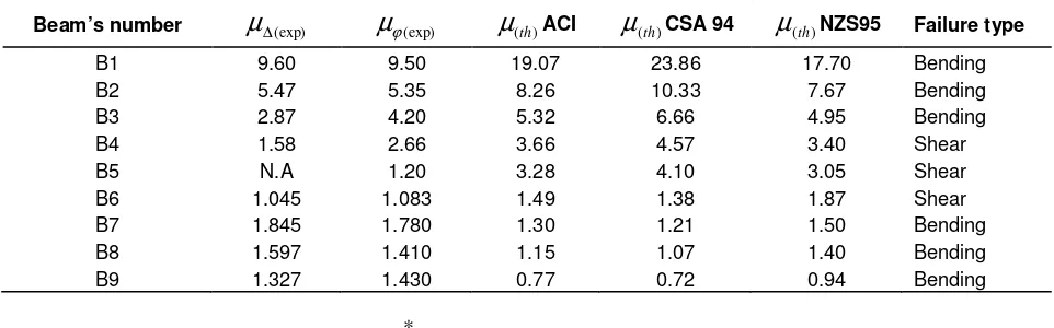
[image:4.612.92.528.75.408.2]Table 3. Comparisons of the theoretical and experimental amount of ductility coefficient (µ).
Beam’s number
µ
∆(exp)µ
ϕ(exp)µ
(th)ACIµ
(th)CSA 94µ
(th)NZS95 Failure typeB1 9.60 9.50 19.07 23.86 17.70 Bending
B2 5.47 5.35 8.26 10.33 7.67 Bending
B3 2.87 4.20 5.32 6.66 4.95 Bending
B4 1.58 2.66 3.66 4.57 3.40 Shear
B5 N.A 1.20 3.28 4.10 3.05 Shear
B6 1.045 1.083 1.49 1.38 1.87 Shear
B7 1.845 1.780 1.30 1.21 1.50 Bending
B8 1.597 1.410 1.15 1.07 1.40 Bending
B9 1.327 1.430 0.77 0.72 0.94 Bending
y u ∆ ∆ ∆ ∗ ∗
=
(exp)µ
, u uf
∆
=
∆
∗∗8
.
0
, y
u
ϕϕ ϕ
µ *
(exp)= , =0.8
∗
u
ϕ
ϕ
uf, NA = not available.
in elements at different levels of loading. Therefore the variations in the stiffness of beam elements occur during each loading stage by a variation of moment inertia and modulus of elasticity. With regards to the effect of cracking on the stiffness of bending elements and the neutral axis depth variation, the design codes use a reduction factor for correction of the effect of stiffness in the design of concrete structural members. Prior to the early 1960s, researchers had developed relationships to determine the modulus of elasticity of concrete accurately (ACI, 1966), but there is no accurate method to determine the moment of inertia as a function of the factors mentioned above.
Therefore, the only means of estimating the deflection that a reinforced concrete member may experience at service load was to conservatively use the cracked moment of inertia (Icr) or un-conservatively use the gross moment of inertia (Ig) of the cross-section. Almost
accurate, the Branson model (Branson, 1965) demonstrated in Equation 2 is used to calculate the effective moment of inertia, which is considered an average value of the moment of inertia along the length of a member. The following formula was adopted by the ACI code [ACI 318, 1989] later.
Ie = (Mcr/Ma)3Ig + [1-(Mcr/Ma)3]Icr < Ig (2)
where, Ie, Ig, Icr, Ma, fr and yt are the effective moment of
inertia, gross moment of inertia, cracked moment of inertia, applied moment from which deflection is calculated, the modulus of rupture of concrete and the distance of extreme tension fibre from the central axis of the cross section, respectively.
The value Mcris obtained from Equation 3;
Mcr = fr × Ig/yt. (3)
As previously discussed, the moment of inertia changes during the loading process and the modulus of elasticity also changes depending on the material characteristics of the concrete and the load. However, preventing brittle failure in a structure is one of the major concerns of structural engineers. Thus we need to study bending element behaviour by variation of stiffness as an effective index on beam displacement and curvature.
For this purpose, in these two groups of beams we take into consideration the ductility of these beams during the loading process. The capacity of a section to develop post-elastic deformations, and thus to dissipate energy, can be quantified by the sectional ductility factor. The ductility coefficient µ is calculated based on Equation (4) in accordance with 3 codes of practice: ACI, CSA (CSA, 19940, and NZ95 (NZS, 1995) and presented in Table 3.
2 5 . 0 2 2
1
)
(
1
(
2
)
)
(
y s c cuf
n
n
n
E
f
ρ
ρ
ρ
ρ
αβ
ε
µ
=
′
+
−
+
(4)where ρ , fy , fc′, n, and Es are tensile bar percentage,
yield strength of the tensile bar, compressive strength of concrete, modular ratio, and modulus of elasticity of the steel bar, respectively.
As presented in Table 3, the experimental ductility index (
µ
∆(exp)) is obtained based on the deflection value and the ratio of the maximum deflection to the yield deflection (∆
y).∆
yis defined as the deflection corresponding tothe initiation of the tensile steel yield. The maximum deflection
∆
µis replaced with 0.8(∆uf ), which is the [image:5.612.69.550.95.245.2]Mohammadhassani et al. 487
Figure 3. Load-stiffness of low reinforced beams with regard to Equation 4.
In this way, the ductility of the reinforced concrete section can also be expressed in the form of the curvature of ductility (
u
ϕ) as the ratio of ultimate curvatureϕ
µto theyield curvature
ϕ
y.ϕ
µis the curvature at ultimate ductilitywhen the concrete compression strain reaches a specified limiting value and is considered at the 80% of failure load of each beam under loading. Therefore,
ϕ
µ isreplaced with 0.8(
ϕ
uf ).ϕ
uf is the amount of curvaturewhen a fracture occurs and
ϕ
y is the curvature when the tension reinforcement first reaches the yield strength.As Table 3 presents, the effect of the tensile bar percentage is evident in the variation of the ductility index. By increasing the tensile bar percentage in the section that full bending capacity obtained, the ductility index has decreased. The ductility index in the bending section is affected by deflection and curvature, as discussed above, and these two main serviceability components of beams are affected by variations in bending stiffness. This relation occurs when the requested plastic deformation by moment redistribution along the bending section provides sufficient ductility. Design codes achieve this by specifying rules that ensure the tension steel yields. In the ACI 318 code (which specifies a minimum reinforcement strain of 7500 micro strain) and implicitly in the case of BS 8110 and EC2 (which links percentage redistribution to neutral axis depth) very high reinforcement strains can be expected. As the stiffness properties of concrete members are based on the cracked and/or un-cracked sections thus, in the following, ductility is discussed with regard to the variation of bending stiffness.
The following submitted method is based on the analysis of all data about displacement reading gathered from LVDT in 3 different points along the beam’s length by referring to Figure 2. By applying the displacement equation based on the elastic bending theory and structural analysis, bending stiffness is calculated using Equation 5.
exp 2 2 exp
48
) 4 3 ( )
(
∆ −
= Pa l a
EI
(5)
where P,
a
and∆
exp are the applied service load, distance of the applied point load from the support face, and the maximum deflection at service load, respectively.In this study with regard to test arrangements and the tested beams, the parameters in Equation 4 are:
a
=0.45 m as shear span and L=1.70 m as two support distance. Therefore the value of EI has been calculated based on Equation 4 for each beam separately, and the related graphs are indicated in Figures 3 and 4.Figure 4. Load-stiffness of high reinforced beams with regard to Equation 4.
Figure 5. Yield curvature (φy) and ultimate destructive curvature
(φuf) in bending section.
another around the yielding state.
Curvature is a second way that bending stiffness can be evaluated, as presented in Figure 5 and described in Equation 6.
ϕ
M
EI (exp) =
(6)
In Figure 5, the amounts ofεc, εs, Xy, and Xu are concrete
strain in extreme compression fibre, tensile bar strain, neutral axis depth at the yielding state, and neutral axis depth at the ultimate state, respectively.
The value of the curvature can be determined by using Equation 7 and by substituting the values for the concrete and steel strain obtained during the loading process.
d tagϕ =ϕ = εc +εs
(7)
Based on Equation 6, the experimental stiffness amount has been drawn for 2 sets of low and high tensile bar percentage separately.
As demonstrated at the initial yield point (the latest point in the graphs), it can be concluded that with increasing tensile bar percentage, at the same load, bending stiffness will increase in spite of a reduced ductility index. The following figure is drawn to present the stiffness variation of high strength over reinforced concrete beams.
[image:7.612.185.435.326.456.2]Mohammadhassani et al. 489
Figure 6. Load-stiffness variation of low longitudinal bar percentage based on curvature data analysis.
Figure 7. Load-stiffness variation of high longitudinal bar percentage based on curvature data analysis.
compared to low tensile bar percentage.
Thus by finding the relation of stiffness variation to tensile bar percentage by variation of ductility, it is important to study this variation along the beam length at different locations regarding the formation of cracks.
It is an important procedure in the design of flexural concrete elements when the moment redistribution
[image:8.612.141.481.76.313.2] [image:8.612.141.476.375.601.2]Figure 8. Stiffness variation for B6 along the beam length.
the actual distribution of EI after crack occurrence. The beam is then reanalyzed, but the bending moment distribution will now have changed because of the changes in EI and the reinforcement layout must now be adjusted to accommodate the new bending moment distribution. This again changes the EI distribution, prompting another analysis and another adjustment of the reinforcement layout along the beam length. The procedure can become unstable and is thus unsuitable for practical design purposes.
Similar comments can be made concerning the use of the gross section, and this trial will terminate as at all sections of the beam’s length an equilibrium equation in compression and tension occurs and needs to be considered as prone points and areas. An elastic analysis is controlled by the hypothesis concerning the value of the flexural stiffness (EI) along the member length. The elastic analysis is permitted by design codes for use at the ultimate limit state (ULS) and thereby allows for nonlinear behaviour by permitting a limited amount of moment redistribution from one part of the structure section to another. Reinforcement is normally designed for the ULS assuming there is a constant EI along the member, but with the appearance of cracks, and thus the change in the stiffness, the design procedure is different.
Recommendations in the design codes vary from one extreme to the other; for example, the EC2, which is non-specific, to the BS 8110 [BS 8110, 1997], which gives three options for calculating the EI value at any particular section.
For a comparison of bending stiffness along the beam length and promoting the effect of the moment of inertia in the sectional bending stiffness variation, the bending stiffness variation for an over-reinforced beam was calculated at 3 points along the beam’s length based on Equation 4. The submitted results are up to yielding-point state of the tensile bar due to the validation of Equation 6 until the yielding of the tensile bar. The bending stiffness
has been plotted for each beam, as illustrated in Figures 8, 9, 10 and 11.
As seen in Figure 8, the amount of stiffness is very close at the middle, and at 20 cm from the mid-point and at 40 cm from the mid-span the difference is negligible.
In Figure 9, the amount of stiffness increases gradually and decreases slowly near the yield point. This illustrates that the yield point has an important effect on the tensile bar percentage and bending stiffness, which increases as the bar strain increases.
The stiffness variation along the length of beam B8 as demonstrated in Figure 10 is the same for the other beams, as in B6. At span and at 20 cm from the mid-span, the amount of stiffness is the same while it is different at 40 cm from the mid-span. But the stiffness variation decreases at the commencement of the loading process due to the propagation of cracks toward the support.
For beam B8, the intersection point is due to the priority of shear deformation earlier than the bending behaviour at this loading point. The reality of this point is that some threaded bars are used in two sides of beam and two plates at the top and bottom of the shear span of the beam to prevent shear failure. This strengthening method acts in a safe way to earn the full bending capacity of beam, but in this beam before this point the treated bar was loose and the shear deformation was permitted. By fastening this shear strengthening bar tightly or by activation of the bending area at this loading point and with the appearance of tension cracks, all three graphs cited the correct and predicted location with a constant gradient. For beam B9 as indicated in Figure 11, the variation of stiffness is also more in mid-span in comparison with further from mid-span.
Thus generally, as seen in these Figures, the stiffness at the middle of the beam’s length is higher than at 20 and 40 cm from the mid-span location. Therefore it can be evaluated in terms of connection joints as a high zone
Mohammadhassani et al. 491
[image:10.612.172.457.75.250.2]Figure 9. Stiffness variation for B7 along the beam length.
Figure 10. Stiffness variation for B8 along the beam length.
Figure 11. Stiffness variation for B9 along the beam length.
20 cm further than mid span 40 cm further than mid span
20 cm further than mid span
20 cm further than mid span 40 cm further than mid span
[image:10.612.169.462.307.494.2] [image:10.612.166.462.550.715.2]of negative moment and at mid-span with a positive moment. Considering the stiffness variation graphs of beams with a high tensile bar percentage that has yielded presents that the stiffness variation is constant around and before the yielding of the tensile bar and, with increasing tensile bar percentages, that this trend tends to act in a constant manner. This constant variation of bending stiffness is a reason on a nearly constant amount of ductility and hence a low variation on neutral axis depth. Thus the bending moment distributions actually develop along the beam, even at the serviceability limit state (SLS), which differs from those obtained from the analysis that uses the concrete section approach. This redistribution will be very small prior to cracking, but after cracking the ratio of EIspan/EIsupport will
normally increase with a corresponding increase in the level of redistribution, even though the reinforcement behaves elastically. The magnitude of this redistribution can be quite high, as considered in the comparison of stiffness variation along the beam length in Figures 9, 10, and 11.
Neutral axis depth variation
The neutral axis is in the cross section of a beam or can be thought of as an invisible line along which there are no longitudinal stresses or strains. The location of neutral axis depth (N.A.D) is at the geometric centre if the section did not curve before the bending occurrence. As the beam is loaded past the cracking point (greater than Pcr) and with an increase in load, cracks will grow and
propagate upward, toward the neutral axis of the beam. All fibres below the neutral axis are in a state of tension, while those on the opposite side are in compression.
Therefore by the “intermediate value theorem”, there must be some point in between the top and the bottom that has no strain that has been named as the neutral axis point.
For the design of concrete sections, all the design codes submit the design process of reinforced concrete element designations with regard to neutral axis depth variation as a needful evaluation of equilibrium in tension and compression forces on either side of it. For example, BS 8110 imposes a minimum neutral axis depth of 0.11 d (where d is the effective depth to the tension steel) although this was introduced for practical reasons and because the top surfaces of beams and slabs are often quite rough and, consequently, it was deemed sensible to restrict the lever arm used in design calculations.
The neutral axis depth and its variations are important parameters in the ductility index and for design purposes. Consequently, designers have effectively worked on the assumption that the reinforcement will be able to develop whatever level of strain is actually required by a specified neutral axis depth and that failure of a section would always be initiated by crushing the concrete in
compression by reaching the ultimate concrete strain in the extreme compression fibre.
Based on Equation 3, any changes in the tensile bar percentage, yield stress of the tensile bar, and concrete compressive strength leads to changes in the ductility index. Also these parameters are effective on N.A.D, as seen in Figure 5 and Equation 8.
For the purpose of experimental study, the amount of
c
ε
andεs was read for each test procedure and with regards to the principal tension and compression distribution. Based on Figure 5, the neutral axis depth can be determined as follows:φ
ε
cx = (8)
c
ε
= the concrete strain in extreme compression fibre, x= the neutral axis depth,=sectional curvature corresponding to the load stages.
Based on the data collected during the experimental process and on Equation 8 the neutral axis depth graphs are drawn for each group of beams separately.
As presented in Figure 12, after the occurrence of the first crack, the neutral axis depth falls, after which it exhibits a constant slope due to the tensile, bar percentage. During the loading process, an abrupt descent occurs after yielding of the tensile bar, which causes a reduction in the compression area with a corresponding fall in the neutral axis depth. In this regard the regress of N.A.D to compression area causes cracks and increasing deflection. This evidence indicates increasing ductility with decreasing N.A.D. Another characteristic of these graphs is the graph’s steep line after yielding point to failure, which indicates the rate of the ductility index. As the graph slope is steeper, the beam failing is more ductile.
It is obvious that with an increase in tensile bar percentage, the angle of hypothetical line plotted from the starting point to the failure point in N.A.D increases, which prevents a further change in the neutral axis depth. Figure 13 presents the experimental results of beams with high tensile depth.
Figure 13 illustrates that, whatever the percentage of tensile bars, the neutral axis depth increases at the ultimate load state. Also the neutral axis depth at a specified load is greater in a beam with a higher tensile bar percentage. This Figure also demonstrates that at the primary loading stage after the first applied load, the neutral axis depth drops off saliently and yields when there is a transmission of load to the steel bars.
On the contrary, with a low reinforced HSC beam, the gradient of the neutral axis variation after the first crack in over-reinforced sections is very low, or in other words the
Mohammadhassani et al. 493
Figure 12. Neutral axis depth variation in low tensile bar percentage.
Figure 13. Neutral axis depth variation in high tensile bar percentage.
change in the compression zone height is nearly constant and is the reason for brittle failure of over-reinforced beams that do not give failure signals, such as cracking and reasonable deflection.
Conclusions
1. Comparison of ductility amounts in tested beams confirms a decrease in ductility by increasing tensile bar percentage. A comparison of the experimental amount of ductility with the theoretical amount, calculated based on 3 codes of practice (Canadian Standard Association
(CSA 94), 1995 New Zealand Concrete Standard (NZS95), and the ACI) reports that as the predicted ductility amount by code in low reinforcement HSC sections is conservative a review of this index in HSC beams with over reinforced section is needed.
[image:12.612.143.483.318.535.2]tensile bars is low, with nearly the same amount as the tensile bar increases.
3. For beams with high longitudinal tensile bar percentage around the initial yield point in the tensile bar, the sectional stiffness is almost constant and the neutral axis depth decreases very slightly. This leads to the failure of over-reinforced beams, which occurs without prior warning signals and fails with an explosion in the compression area.
4. The beam stiffness along the length decreases the farther it is from the mid-span towards the support in simple support beams.
5. The load-neutral axis depth variation graphs exhibit a fall in the neutral axis depth after the occurrence of the first crack and then increase slightly as the transition of stress from the concrete to the tension steel bar occurs. For beams with low tensile bar percentages, a sudden drop occurs after the yielding of the tensile bar, which causes a reduction in the compression area. The variation of the neutral axis before and after the yielding point is very low in beams with high tensile bar percentages, which gives an indication of the loading stiffness and ductility behaviour of the beams.
6. From load-N.A.D graphs, the angle of the hypothetical line drawn from the start of the first crack to the failure point indicates an indicator in recognizing the ductility index, as the slope of the line is steeper, the related beam failing is more ductile.
ACKNOWLEDGMENTS
The authors gratefully acknowledge the Kerman Cement Industrial Group (Registration and Exploit code: 170) for financial support of this study, the Fakhr Avaran Kerman Consultant Office in preparing the background of this research and Dr Babak Kamali for technical aspects of this paper.
REFERENCES
ACI Committee 318 (1989). Building Code Requirement for Reinforced Concrete and Commentary (ACI 318-89/ACI 318R-89). Am. Concr. Inst. Detroit.
Aitcin PC, Mehta PK (1990). Effect of Coarse-Aggregate Characteristics on Mechanical Properties of High-Strength Concrete. ACI Mater. J., 87: 103-107.
Akbarzadeh H, Maghsoudi AA (2010). Experimental and analytical investigation of reinforced high strength concrete continuous beams strengthened with fiber reinforced polymer. Mater. Des., 31: 1130-1147.
Branson DE (1965). Instantaneous and Time Dependent Deflection of Simple and Continuous Reinforced Concrete Beams. HPR Report No. 7, Part 1, Alabama, Highway Department/US Bureau of Public Roads.
British Standards Institution. BS 8110 (1997). Structural Use of Concrete Part 1: Code of Practice for Design and Construction.
Carrasquillo RL, Slate FO, Nilson AH (1981). Properties of High-Strength Concrete Subjects to Short-Term Loads. ACI. J., 78. Chan HC, Chung YK, Huang YP (1993). Analytical Crack Model for
Reinforced Concrete Structures. J. Struc. Eng. ASCE., 199: 1339-1357.
CSA 94, CSA Technical Committee (1994). Design of Concrete Structure for Buildings. CAN3-A23.3-M94, Canadian Standards Association, Rexdale., Ontario.
Elmenshawi A, Brown T (2010). Hysteretic energy and damping capacity of flexural elements constructed with different concrete strengths. Eng. Struc.,32: 1297-1305.
Fasching CJ, French CE (1999). Effect of High Strength Concrete (HSC) on flexural members and high strength concrete in seismic regions. ACI Int. J., Sp-176.
Ghanbari F (2004). Analysis and design of high strength concrete beams with low longitude tensile bar percentage in seismic hazard area. Civil Engineering Department, Kerman University, Kerman, Iran.
Grossman JS (1981). Simplified Computations for Effective Moment of Inertia and Minimum Thickness to Avoid Deflection Computations. ACI J., (78): 423-434
Ho JCM, Lam JYK, Kwan AKH (2010). Effectiveness of adding confinement for ductility improvement of high-strength concrete columns. Eng Struc., 32: 3714-3725.
Ibrahim HHH, MacGregore JG (1994). Flexural behaviour of high strength concrete columns. Struc. Eng. Rep. No. 196, Dept. Civ. Eng. Univ. Alberta, Canada, March, p. 197.
Iravani S (1996). Mechanical Properties of High-Performance Concrete. ACI Mater. J., 93: 416-426.
Lubliner L, Oliver J, Oller S, Oñate E (1989). A plastic-damage model for concrete. Int. J. Solids Str., 25: 299-326.
Mohammadhassani M (2004). Analysis and design of high strength concrete beams with high longitude tensile bar percentage in seismic hazardous area. Civil Engineering Department, Kerman University, Kerman, Iran. September.
NZS95, Standards New Zealand (1995). Design of Concrete Structures. NZS3101, Wellington, New Zealand.