International Journal of Emerging Technology and Advanced Engineering
Website: www.ijetae.com (ISSN 2250-2459, ISO 9001:2008 Certified Journal, Volume 4, Issue 6, June 2014)
824
Impact Analysis of Laminated Composite on Glass Fiber and
Carbon Fiber
Sunith Babu L
1, H. K. Shivanand
21Assistant Professor, Dept. Of Mech. Engg. M.S.R.I.T, BANGALORE 2Professor, Dept. Of Mech. Engg. UVCE, BANGALORE
Abstract--This paper focus on investigating the impact property of laminated composites.The test are performed based onASTM standardsD3029 and D7137.The impact test were carried out using an instrumented drop weight test. The behavior of E-glass/epoxy and carbon fiber laminated composite plates has been experimentally studied under impact of steel projectile at low velocities. The results were obtained using a drop weight impact machine and presented for cross-ply laminates [0 - 90] combination. The time history of the impact process such as the load, energy, velocity for both laminates is determined for a target square plate of 2mm thickness and deflection due to an impact force acting at the centre. The effects of the projectile velocities and lamination sequences on composite plate’s behavior have been discussed.
Keywords--Low velocity impact, Laminates, Drop Dart Testing Machine
I. INTRODUCTION
Extensive research has been undertaken into the effects of low-velocity impact on composite laminates over the past few decades. Research continues to be conducted in this field due to the detrimental effects low-velocity impacts can have on the residual properties of composite laminates.
Fiber-reinforced composite materials are known for their high weight-specific mechanical properties and are therefore used in numerous lightweight engineering applications, in particular in aircraft design. However, a constant concern for such laminates – much more than for similar metallic structures – are impact loads of foreign objects, which can cause internal material damage. Thisdamage can significantly reduce the strength and it can growunderload and may be difficult to detect. Typical impact scenarios inaircraft design range from a tool dropped on the laminate surface(high mass, low velocity), over runway debris thrown up by thetires or hail (low mass, high velocity) to bird strike during flight(high mass, high velocity).
The main goal of this work is to present and discuss some experimental results obtained during a low velocity impact testing campaign conducted on glass & carbon fiber epoxy matrix laminate plates.
The impact behavior of this particular class of composite material is then analyzed from an energy viewpoint, by means of two parameters [1]: the saturation impact energy and the damage degree of a plate specimen subjected to a drop-dart test according to the ASTM D3029 standard [2]. The drop dart tests have been conducted selecting different levels of the dart kinetic energy at impact by modification of the drop height. Thus, impact velocities are different in one test from the other and, consequently, the material of the plates is submitted to different deformation rate
1.1 Carbon fiber-reinforced plastic (CFRP or CRP),is a very strong, light, and expensive composite material or fiber reinforced polymer. Similar to fiberglass (glass reinforced polymer), the composite material is commonly referred to by the name of its reinforcing fibers (carbon fiber). The crystal alignment makes the fiber very strong for its size. Several thousand carbon fibers are twisted together to form a yarn, which may be used by itself or woven into a fabric.
1.2 Glass-reinforced plastic or GRP is a composite material made of a plastic matrix reinforced by fine fibers made of glass. GRP is a lightweight, strong material with very many uses, including boats, automobiles, water tanks, roofing, pipes and cladding. Furthermore, by laying multiple layers of fiber on top of one another, with each layer oriented in various preferred directions, the stiffness and strength properties of the overall material can be controlled in an efficient manner. In the case of glass-reinforced plastic, it is the plastic matrix which permanently constrains the structural glass fibers to directions chosen by the designer. With chopped strand mat, this directionality is essentially an entire two dimensional plane; with woven fabrics or unidirectional layers, directionality of stiffness and strength can be more precisely controlled within the plane.
II. FABRICATION OF COMPOSITE SPECIMENS
2.1 Steps Involved in Preparing Specimen
International Journal of Emerging Technology and Advanced Engineering
Website: www.ijetae.com (ISSN 2250-2459, ISO 9001:2008 Certified Journal, Volume 4, Issue 6, June 2014)
825
Glass-reinforced plastic or GRP is a composite material made of a plastic matrix reinforced by fine fibers made of glass The bi-woven clothes are available in the standard form of 0.2mm thickness. Bi-Woven cloths are cut to the required size & shape.These cloths are stacked layer by layer of about 8 layers to attain the thickness of 2mm as per the ASTM Standard Specimen. Bonding agent (epoxy resin) is applied to create bonding between 16 layers of sheet, in the ratio of 100:1
RESIN 100%: HARDNER 1% 50 grams of resin is used. the process of polymerization is called “curing”, and can be controlled through temperature and choice of resin and hardener compounds; the process can take minutes to hours. Some formulations benefit from heating during the cure period, whereas others simply require time, and ambient temperatures.
Process of vacuuming will be done to remove air traps exist between the layers.
Vacuuming & Room curing to be done about 3hrs. Post Curing.
After vacuuming & Room curing the material
[image:2.612.329.558.424.656.2]To be post cured.Prepared plates of carbon & Glass fibers are placed in Owen. At a temperature of about 1000C up to 2hrs.After curing process the materials cut to the required size & Shape as per ASTM Standards.
Fig 1 Bi-woven clothes of Carbon and E-Glass
2.2 For impact test specimen
Specimens were manufactured from E-glass woven roving of weight 300 g/m using a hand lay-up process. A polyester resin was used and once cured, the panels were cut into specimens of 150*150 mm in dimension with an average thickness of 2 mm and stacking sequence of [0/90].
Aluminum end tabs were bonded to the specimens to prevent matrix crushing and stress concentrations induced by the grips on the test rig.
III. 3.EXPERIMENTATION METHOD
3.1 Impact testing
3.1.1 Low velocity impact test conditions-The low velocity impact testing was conducted on a Dynatup 8250 drop tower facility. The CFRP& GFRP plate had to be positioned under this drop tower and should also be preloaded in compression. Therefore, a special specimen fixture was designed and fabricated that allows for a specific uniaxial compressive preloading.
For all impact tests in this study a hemispherical steel impactor with a diameter of 1 in. (25.4 mm) and a mass of 2.11kg was used (Fig. 2). The clamping conditions of the CFRP & GFRP plates include a fixed support of the longitudinal ends and a simple support of the lateral sides, as illustrated before. All three materials were tested with and without preloading. To limit the complexity of this study, a reference energy level of 40 J was chosen. Since the impactor mass was constant, this corresponds to an impact velocity of 3.53 m/s. Few additional tests with material types were conducted with 30 J.
[image:2.612.59.278.442.639.2]International Journal of Emerging Technology and Advanced Engineering
Website: www.ijetae.com (ISSN 2250-2459, ISO 9001:2008 Certified Journal, Volume 4, Issue 6, June 2014)
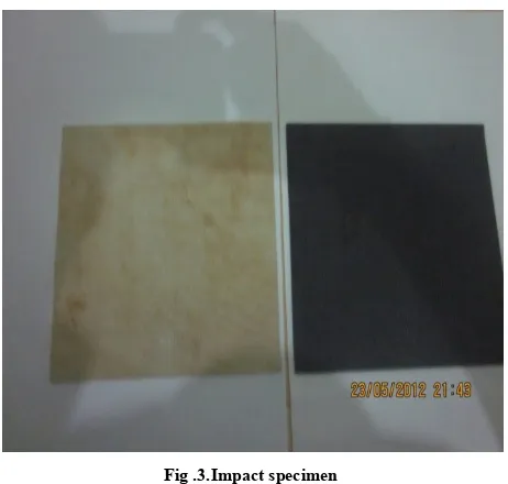
[image:3.612.54.285.131.351.2]826
Fig .3.Impact specimenTo accurately apply the desired level of preload, an oscilloscope was attached to the hydraulic rams. Load was applied through the hydraulic rams until the corresponding voltage was reached. Once the desired voltage was reached, the specimens were impacted and the preload was immediately released followed by loosening of the grips to avoid any damage propagation.The experimental tests were performed on 16 specimens for every material type. We analyze in some detail the results for a glass fiber laminate [0/+90/-90]s made of unidirectional laminae, behaving in a similar way to the other layups. Preliminary tests indicated a high level of repeatability at all energy levels and so it was considered sufficient to perform the test only two times at nine energy levels determined by the falling height, namely 250, 300, 400, 500, 600, 700 mm.
The corresponding values of the nominal impact velocity
are 0.70, 0.99, 1.14, 1.72, 1.85, 1.98, 2.10, 2.22 and 2.42 m/s.
3.2 Test method
Drop Weight Impact testing machine was used for carrying out this test. A schematic diagram of the test is shown in Fig 4. Energy, Velocity and Load vs. Time data is acquired by the data acquisition system. The initiation and propagation energy are calculated using this data. Impact energy corresponding to the maximum impact force is defined as initiation energy. Propagation energy is defined as the difference between the maximum impact energy and the initiation energy. Three different velocities and two different hammer weights were used for doing the impact testing. Specimens were tested at velocities of 2m/s to 4m/s using hammer weights of 2.29kg.
[image:3.612.335.553.327.532.2]Each group was tested at three different locations namely Bay, Rib and Node that surrounded the center of the specimen and the response was acquired.
International Journal of Emerging Technology and Advanced Engineering
Website: www.ijetae.com (ISSN 2250-2459, ISO 9001:2008 Certified Journal, Volume 4, Issue 6, June 2014)
827
[image:4.612.338.550.123.687.2]IV. RESULTS AND DISCUSSIONS
Table 1 For low impact test
Parameters
Low impact from 500mm height
Low impact from 400mm height Carbon fiber laminate Glass fiber laminate Carbon fiber laminate Glass fiber laminate Impact energy 8.6671,jo ule 8.6306,j oule 8.5497,j oule 6.3053,j oule Energy to max load 0.0730,jo
ule 0.0164,joule 0.0559,joule 0.0837,joule
Total energy 0.0869,jo ule 0.0176,j oule 0.0572,j oule 0.1198,j oule Energy to yield 0.0050,jo ule 0.0014,j oule 0.0045,j oule 0.0000,j oule Impact velocity 2.6332,m /sec 2.6276, m/sec 2.6153, m/sec 2.2459, m/sec Velocity slow down -1.0544,% -0.3421, % -0.6474, % -1.4005, % Maximum load 0.0084,k
n 0.0071,kn 0.0103,kn 0.0092,kn
Load at yield 0.0050,k n 0.0035,k n 0.0057,k n 0.0000,k n Time to max load 3.9520,m sec 1.1690, msec 2.5920, msec 4.7130, msec Time to yield 0.4656,m
sec 0.1536,msec 0.3864,msec 0.0000,msec
Total time 4.5980,msec 1.2360,msec 2.6400,msec 6.4990,msec
Defl at max load
10.4717,
mm 3.0829,mm 6.8085,mm 10.6690,mm
Defl at
yield 1.2332,mm 0.4100,mm 1.0174,mm 0.0000,mm
Total deflection 12.1910, mm 3.2601, mm 6.9348, mm 14.7455, mm
Slope 0.0040,kn/mm 0.0085,kn/mm 0.0056,kn/mm .00
From the experiment conducted we observed,
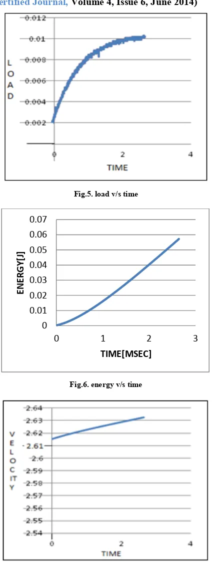
Impact test for carbon fiber laminate for 2mm thickness and 500mm Height
Fig.5. load v/s time
Fig.6. energy v/s time
Fig.7. velocity v/s time 0 0.01 0.02 0.03 0.04 0.05 0.06 0.07
0 1 2 3
ENE
RGY[J
]
[image:4.612.51.287.168.593.2]International Journal of Emerging Technology and Advanced Engineering
Website: www.ijetae.com (ISSN 2250-2459, ISO 9001:2008 Certified Journal, Volume 4, Issue 6, June 2014)
828
Impact test for glass fiber laminate for 2mm thickness and 500mm HeightThe results of the impact tests on unloaded and preloaded GFRP plates are summarised
The energy is computed here from the initial kinetic energy Ekin(t0) of the impactor, its mass Mimp and velocity v(t). A photoelectric sensor was used to measure the initial velocity v(t0)before impact.
Fig.8. load v/s time
Fig.9. energy v/s time
Fig.10. velocity v/s time
Acknowledgement
Authors would like to thank MSRIT & UVCE
Bangalore for carrying out the experimentation
V. CONCLUSIONS
For impact
The experimental test series showed an increased deflection for carbon composite plates, which led to higher extent of material damage as compared to glass fiber laminates with energy absorption capacity being lower in CFRP laminates as compared to GFRP laminates
From the above results CFRP has less impact strength than GFRP laminates.
REFERANCES
[1] Kelkar A.D, Sankar J, Grace C. Behavior of tensile preloaded
composites subjected to low-velocity impact loads. In: Recent advances in solids/structures and application of metallic materials. ASME, 1997;369: 39–46.
[2] Chiu S-T, Liou Y-Y, Chang Y-C, Ong C-L. Low velocity impact
behavior of prestressed composite laminates. Mater Chem Phys 1997; 47:268–72.
[3] Rhodes .M.D.,Mikulas .M.M. and McGowan .P.E „Effects of
orthotropy and width on the compression strength of graphite epoxy panels with holes‟ AIAA Journal 22 No 9 (1984)pp 1283- 1292.
[4] Soutis .C and Fleck .N.A „static compression failure in carbon
fiber-epoxy T800/924C Composite plate with a single hole‟ J Comp.Mater 24 No 5 (May 1990)pp 536-558.
[5] Port .R.T „The compressive strength of CFRP‟ RAE Technical
Report TR-82083(1982). 0
0.005 0.01 0.015 0.02
0 0.5 1 1.5
EN
ER
GY[K
N
]
International Journal of Emerging Technology and Advanced Engineering
Website: www.ijetae.com (ISSN 2250-2459, ISO 9001:2008 Certified Journal, Volume 4, Issue 6, June 2014)
829
[6] Kelkar AD, Sankar J, Grace C. Behavior of tensile preloaded
composites subjected to low-velocity impact loads. In: Kwon YW, editor. ASME recent advances in solid/structure and application of metallic material. PVP, Vol.369.NewYork:ASME1997
[7] Low Velocity Impact on CFRP plates with compressive preload: