International Journal of Emerging Technology and Advanced Engineering
Website: www.ijetae.com (ISSN 2250-2459,ISO 9001:2008 Certified Journal, Volume 4, Issue 3, March 2014)
380
Parallel-Pipelined Radix-6
Z
Multipath Delay Commutator FFT
Architectures
S. Karthick
1, Dr.S. Dhandapani
21
PG Student, 2Professor, with the Department of Electronics and Communication Engineering, Saveetha Engineering College, Chennai, Tamilnadu, India
Abstract—The new Proposed design has been designed and developed by novel parallel-pipelined Fast Fourier Transform (FFT) architecture. The most important and fastest efficient algorithm is a FFT. FFT is used to computes the Discrete Fourier Transform (DFT). FFT is mainly applied in autocorrelation, spectrum analysis, linear filtering and pattern recognition system. The proposed architectures were designed by using register minimization and folding transformation technique. The critical path is reduced by pipelining and the multiple inputs and multiple outputs are computed by parallel processing. Furthermore, 2,
radix-3, radix-6Z decimation in time and decimation in frequency
algorithm can be used. As a result, the radix-6Z has been
developed to reduce the complexity of hardware and the computational intension. The power dissipation can be decreased and unwanted operations are stopped by using the clock gates.
Keywords— Fast Fourier Transform (FFT), radix 6, Pipelining, Parallel processing, Multipath Delay Commutator (MDC).
I. INTRODUCTION
Discrete Fourier Transform (DFT) is prodigious proliferate utilized in a lot of fields. Especially in data compression, partial differential equations, polynomial multiplications, filter bank and Spectrum analysis [1]-[6]. In outstanding, we current vital computational algorithms, called Fast Fourier Transform (FFT). FFT is a technique for computing the DFT with diminishes number of complex multiplications. FFT algorithms are starting point on the acute principle of length 6Z in to consecutively smaller discrete Fourier transforms. There are basically two types of FFT algorithms. They are Decimation-in-time (DIT) and in-Frequency (DIF). In Decimation-in-time, the output is in natural order while the input is bit reversed. The sequences for which we need the DFT is successively divided in to smaller sequences and the DFTs of these sub sequences are combined in certain pattern to obtain the required DFT of the entire sequence. In the Decimation-in-frequency the input is normal order while the output is bit reversed.
The Fast Fourier Transform algorithm exploits the two basic properties: Symmetry and Periodicity. In order to meet the aloft execution and real time needs of up-to-date applications, hardware designers have always tried to fulfil efficient architecture for the computation of FFT. The most broadly used algorithms are called length N=2m, that can be expressed as radix-2, radix-4, radix-8 [7]-[10]. Later, the designers have found the new design algorithms for length N=3m, that can be expanded by radix-3, radix-6, radix-9 [11]-[13]. Later, The Scientist introduce the pipelined radix 2K feed forward FFT architecture [14]. It is used to increase the processing speed of the architecture. Then the scientist introduces the split radix algorithm for length 6M DFT [15]. It is used to reduce the area of the architecture. The new parallel-pipelined Radix 6Z Multipath Delay Commutator (MDC) FFT architecture is used to reduce the delays and increase the processing speed of the architecture. In these circumstances, both parallelism and pipelining concept is used [16]-[19]. Since pipelining is used to reduce the critical path, power consumption and to increase the clock speed.
The pipelining architecture can be classified in to two types. They are Single path delay Feedback (SDF) and Multipath Delay Feedback (MDF). The SDF is used to the output is fed back to the input. So this type of architecture is called feedback architecture [20]-[21]. The MDF is used one of the output is connected again forward to the next block of the input. So this type of architecture is called Feed forward architecture [22]. This multipath delay feedback is also known as multipath delay commutator. Parallel processing is used to increase the sampling rate by replicating the hardware. The several numbers of inputs are processed and several no of outputs are taken simultaneously.
International Journal of Emerging Technology and Advanced Engineering
Website: www.ijetae.com (ISSN 2250-2459,ISO 9001:2008 Certified Journal, Volume 4, Issue 3, March 2014)
381 Previously radix 2k algorithm can be used to implement this architecture. This architectures involves many unwanted operations are occurs. Overcome this problem by the new proposed design of parallel pipelined FFT architecture. The clock gate can be mainly used in this proposed model. Finally, the present need of high throughput and increased processing speed can be achieved by the new proposed design. Furthermore, to reduce the power dissipation and to stop the unwanted operations can be achieved by using the clock gates.
The remaining of this paper is organized as the following sections: In Section II basics of radix-2, radix 2k, radix 3 and radix 6Z FFT architecture are given. In Section III Data shuffling process is introduced. In Section IV, proposed design is explained. In Section V, experimental results of proposed design are analysed. In Section VI, conclusion and the scope for future work is given
.
II. BASICS OF PIPELINED RADIX 2,RADIX 2K RADIX 3AND RADIX 6ZFFTALGORITHM AND DATA SHUFFLING
FFT is a numerically efficient algorithm used to compute the DFT. An efficient implementation of the DFT is possible using the parallel pipelined FFT architecture. Different types of radix are applied in the proposed work. This is explained in the sub sections A, B and C.
A. Radix-2 and Radix2k FFT Architecture
The DFTs of the decimated sequences are given below:
L-1
Z (p) = ∑ x (l) wLKl , 0 ≤ k ≤ L-1 (1) l=0
WL = e-j2π/L
Where x(l) is the input sequences, WL is the phase factor or twiddle factor.
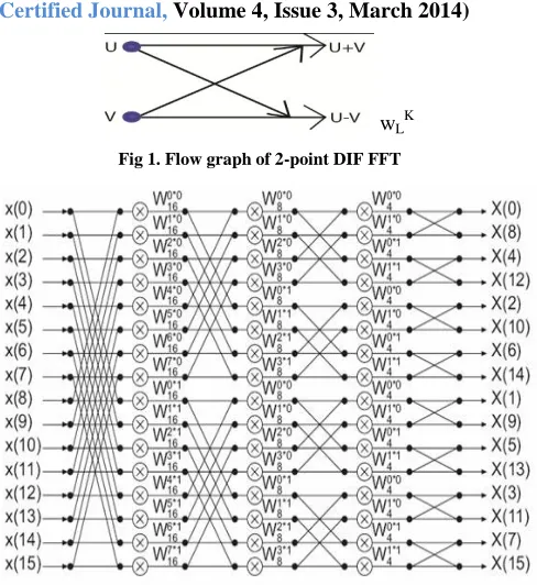
In Fig 1, the basic radix 2 flow graph is illustrated. Normally, Decimation-in-time or Decimation-in-frequency algorithm used in this graph. And also phase factor is multiplied in below arrow or in both (above and below arrows). This radix 2 algorithm is applied in pipelined architecture. The radix 2 flow graph is shown in Fig 1. The radix
2
k algorithm is the advancement of radix 2 algorithm. K is the real numbers like 0, 1,2,3,4,5...etc. This algorithm compares the different length of pipelined architecture. Specially compares the processing speed and the area. The radix2
4 is denotes 16 point FFT architecture. The basic radix 2 DIF algorithm is shown in Fig 2. [image:2.612.326.570.120.386.2]wLK
Fig 1. Flow graph of 2-point DIF FFT
Fig 2. Flow graph of 16-point radix 2 DIF FFT
B. New Radix 3 and radix 6 FFT architecture
In Fig 3 represents the new radix 3 FFT algorithm. 3-points FFT needs totally 4 multiplications and 12 additions. But some algorithms considered that radix 3 FFT architecture is calculated with 2 multiplications and 12 additions are needed. Because one assess with bit shift. The basic radix-3 equation can be writtenas,
L/3-1 L/3-1 Z (p) = ∑ x (3l) wL3Kl + ∑ x (3l +1) wL (3l + 1) K l=0 l=0
L/3-2 + ∑ x (3l +2) wL
(3l + 2) K
(2) l=0
This equation (2) can be reduced to
L/3-1 Z (p) = ∑ x (3l) wL3Kl l=0
[image:2.612.335.562.499.624.2]International Journal of Emerging Technology and Advanced Engineering
Website: www.ijetae.com (ISSN 2250-2459,ISO 9001:2008 Certified Journal, Volume 4, Issue 3, March 2014)
[image:3.612.51.285.132.238.2]382
Fig 3. Flow graph radix 3 FFT algorithm
Fig 4 illustrates the flow graph of 6-point FFT algorithm. It is the combination of radix 2 and radix 3 FFT flow graph. More complexity can be reduced by this architecture. In this architecture first calculate the algorithm of radix 2 FFT. The twiddle factor is not multiplied in above and below arrows. Then calculate the algorithm of radix 3 FFT. Finally, the two types of flow graph is combined in the same FFT architecture. This is called radix-6 FFT algorithms. In radix-6Z algorithms expansion include 60 , 61, 62, and etc. This algorithm is mainly used to reduce the computational complexity and to reduce the area of hardware chips.
[image:3.612.348.537.210.307.2]. Fig 4. Flow graph of 6-point FFT
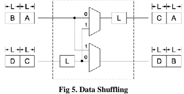
C. Data Shuffling
In this diagram the radix 2 is divided in to four variables. These are A, B, C and D. If one radix 2 is 8 point means, consider each variable has 2 points structure. The MUX is used to shuffling the process. In MUX if the selection 4means, at ‗00‘ condition data of A will go the output buffer at the same time data of C will go to the input buffer. At ‗01‘ condition data of C will go to output buffer.
At ‗10‘ condition data of B will go to second MUX output simultaneously data of D save in input buffer, At ‗11‘ condition only data of D will go to output buffer likewise all data shuffling process is same in this FFT structure. Similarly radix 3 and radix 6Z operations are performed. The data shuffling process is shown in Fig 5.
Fig 5. Data Shuffling
III. PROPOSED DESIGN ALGORITHM
[image:3.612.49.287.401.574.2]The proposed model is mainly used the clock gates in between the radix. The proposed blocks used the algorithm radix 2, radix 3, and radix 6Z algorithm. Data shuffling with basic radix 2, radix 3 and radix 6 shown in Fig 6, Fig 7 and Fig 8. The clock gate is used to reduce the more power consumption. The radix 2K is the advancement of basic radix 2 algorithm. The radix 6Z is a basic radix 6 algorithm. Pipelining and parallel processing also applied in this architecture. Pipelining is used to reduce the critical path and parallel processing is used to more number of outputs processed simultaneously. Fig 6, 7and 8 represents below:
[image:3.612.338.538.481.641.2]International Journal of Emerging Technology and Advanced Engineering
Website: www.ijetae.com (ISSN 2250-2459,ISO 9001:2008 Certified Journal, Volume 4, Issue 3, March 2014)
[image:4.612.334.550.121.311.2]383
[image:4.612.55.266.144.273.2]Fig 7. Data shuffling with basic radix 3 algorithm
Fig 8. Data shuffling with radix 6 algorithm
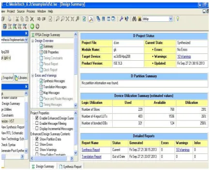
IV. EXPERIMENTAL RESULTS
The synthesis report analysis of area utilization shown in Fig 9 and Fig 10. This blocks are synthesized by Xilinx ISE simulator. The analysis report of radix 2 and radix 6 data shuffling process with clock gates are given below. From the observation it can be observed that in Radix-6 the number of hardware components requirement were low in comparison to that of Radix-2. Thus, because of less number of component requirement the overall area utilized in Radix-6 is far less than that of Radix-2 and so is the overall power consumption as the number of signal shifts are reduced.
Fig 9. Area utilization of radix 6 with data shuffling
[image:4.612.64.267.300.457.2]In radix-6 algorithm, the number of slice registers used is 9 out of 19200, the number of LUTs used is 34 out of 19200 and the number of bonded IOBs used is 61 out of 400.
Fig 10. Area utilization of basic radix 2 with data shuffling
[image:4.612.333.549.373.548.2]International Journal of Emerging Technology and Advanced Engineering
Website: www.ijetae.com (ISSN 2250-2459,ISO 9001:2008 Certified Journal, Volume 4, Issue 3, March 2014)
384
V. CONCLUSION AND FUTURE WORK
The parallel-pipelined architecture can be used to reduce the delay using pipelining method and to reduce the power consumption by using the clock gates and to reduce the area using 6Z algorithm. In future radix 8Z can be used to reduce the area.
REFERENCES
[1] V.Buriako, ―FFT Computation with Systolic arrays, a new architecture,‖ IEEE Transaction on Circuits and Systems, vol. 41, no. 4, pp. 278-284, 1994.
[2] Wei-Hsin Chang and Truong Ngyen, ―An OFDM-Specified lossless FFT architecture,‖ IEEE Transaction on Circuits and Systems, vol. 53, no. 6, pp. 1235-1243, 2006.
[3] M. Frigo and S. Johnson, ―The design and implementation of fftw3,‖ Proc. IEEE, vol. 93, no.2, pp. 216–231, 2005.
[4] D. Sepiashvili, ―Performance Models and Search Methods for Optimal FFT Implementations,‖ M.Sc. thesis, Carnegie Mellon Univ., Pittsburgh, PA, 2000.
[5] J. Garcia, J.A. Michell and A.M. Buron, ―VLSI Configurable delay commutator for a pipeline Split radix FFT architecture,‖ IEEE Transaction on Signal Processing , vol. 47, no. 11, pp. 3098-3107, 1999.
[6] J. Keiner, S. Kunis, and D. Potts, ―Using nfft 3—A software library for various nonequispaced fast Fourier transforms,‖ ACM Trans. Math. Softw. (TOMS), vol. 36, no. 4, pp.19–19, 2005.
[7] I.R. Mactaggart, Jack and A. Mervyn, ―A Single Chip radix-2 FFT butterfly architecture using parallel data distributed arithmetic,‖ IEEE Journal of Solid State Circuits, vol. 19, no. 3, pp. 368-373, 1984.
[8] T. Lenart and V. Owall, ―Architectures for Dynamic data Scaling 2/4/8k Pipeline FFT cores,‖ IEEE Transaction on Very Large Scale Integration (VLSI) systems, vol. 14, no. 11, pp. 1286-1290, 2006. [9] I.R. Mactaggart, Jack and A. Mervyn, ―A Single Chip radix-2 FFT
butterfly architecture using parallel data distributed arithmetic,‖ IEEE Journal of Solid State Circuits, vol. 19, no. 3, pp. 368-373, 1984.
[10] E.E. Swartzlander, W.K.W. Young and S.J. Joseph, ―A radix 4 delay commutator for fast Fourier transform processor implementation,‖ IEEE Journal of Solid-State Circuits, vol. 19, no. 5, pp. 702-709, 1984.
[11] E. Dubois and A. Venetsanopoulos, ―A new algorithm for the radix 3 FFT,‖ IEEE Transaction on Speech and Signal Processing, vol. 26, no. 3, pp. 222-225, 1978.
[12] S. Prakash and V.V. Rao, ―A new radix-6 FFT algorithm‖ IEEE Transaction on Acoustics, Speech and Signal Processing , vol. 29, no. 4, pp. 939-941, 1981.
[13] K.M.M. Prabhu and A. Nagesh, ―New radix-3 and -6 decimation-in-frequency fast Hartley transform algorithms,‖ Canadian Journal of Electrical and Computer Engineering, vol. 18, no. 2, pp. 65-69, 1993.
[14] M. Garrido, J. Grajal, M.A. Sanchez, O. Gustafson ―Pipelined radix 2K feed forward FFT architecture,‖ IEEE Transaction on very large
scale integration system, vol. 21, no. 1, pp. 23-32, 2013.
[15] Weihua Zheng and KenLi Li., ―Split Radix Algorithm for Length 6M DFT,‖ IEEE Signal Processing Letters, vol. 20, no. 7, pp.
713-716, 2013.
[16] M. Ayinala, M. Brown and K.K. Parhi, ―Pipelined parallel FFT architectures via folding transformation,‖ IEEE Transaction on very large scale integration (VLSI) systems, vol. 20, no. 6, pp. 1068-1081, 2012.
[17] Shen-Jui Huang and sau-Gee Chen, ―A High-Throughput Radix-16 FFT processor with parallel and Normal Input/output Ordering for IEEE 802.15.3C Systems,‖ IEEE Transaction on circuits and systems, vol. 59, no. 8, pp. 1752-1765, 2012.
[18] E.H. Wold and A.M. Despain, ―Pipeline and Parallel-Pipeline FFT Processor for VLSI Implementation,‖ IEEE Transaction on Computers, vol.C-33, no. 5, pp. 414-426, 1984.
[19] Harper and T. David, ―Block, multistride vector, and FFT accesses in parallel memory system,‖ IEEE Transaction on Parallel and distributed systems, vol. 2, no. 1, pp. 43-51, 1991.
[20] S. Suruthi and M. Arulkumar, ―pipelined R22 SDF, R4SDC FFT
architecture via folding transformation,‖ International conference on Communication and Signal Processing (ICCSP), pp. 1-4, 2013. [21] Liang Yang, Kewei Zhang, Hongxia Liu, Jin Huang and Shitan
Huang, ―An efficient locally pipelined FFT processor,‖ IEEE Transaction on circuits and systems, vol. 53, no. 7, pp. 585-589, 2006.
[22] Bu-Ching Lin, Yu-Hsiang Wang, Juinn-Dar huang and Jing-Yang Jou, ―Expandable MDC-based FFT architecture and its generator for high-performance applications,‖ IEEE International SOC Conference (SOCC), pp. 188-192, 2010.
[23] D. Takahashi, ―An extended split radix FFT algorithm,‖ IEEE Signal Processing Letters, vol. 8, no. 5, pp. 145-147, 2001.
[24] Weihua Zheng and KenLi Li., ―Split Radix Algorithm for Length 6 DFT,‖ IEEE Signal Processing Letters, vol. 20, no. 7, pp. 713-716, 2013.