Technology (IJRASET)
Prediction of Deflection of Cantilever Beam of Any
Arbitrary Length Using Soft Computation
Technique
Mr. Kumar Gaurav1, Dr. Sankha Bhaduri2, Dr. Arbind Kumar3 1,2,3
Mechanical Engineering Department, B.I.T., Mesra, Ranchi ,India
Abstract- The purpose of the paper is to predict the deflection of a cantilever beam using soft computation technique. The neural networking technique is adopted here for the prediction. The large deflection of the beam is considered in this study for the analysis. The variable length of the beam is considered for the training purpose of the neural network. The aim of the study is to predict the deflection of the beam for any intermediate length of the beam from the data observed from the experimental as well as finite element analysis. It is observed in this study that there is a very close agreement between the predicted data and analytical data.
Keywords-- Finite element analysis, ANN, Variable length, Soft Computation technique, Prediction of Deflection.
I. INTRODUCTION
The geometric non-linearity problem is considered here for the analysis. The presence of non linear term in the governing equation of such problem makes the problem complicated. Therefore an attempt has been taken in this study to solve the large deflection of the cantilever beam using artificial neural networking (ANN) technique.
In 2002 Neipp et al. [1] studied the deflection of cantilever beam by analytically and numerically for both conditions a) Large and b) Small. He followed Bernoulli-Euler relationship of uniform cross-section of beam and derived an equation of beam in non-linear terms for both conditions. He got the approximate same results.
In 2002 Lee [2] studied analysis of large deflection of cantilever beam under combined loading by using Ludwick relation and Bernoulli-Euler bending moment relationship of uniform cross-section rectangular beam and obtained equation is solved by One-parameter shooting method. The result was compared with the result of ‘G.Lewis’ result.
In 2005 Dado and Al-sadder [3] summarized several approaches which are used in large deflection problems. The first approach based on elliptical integral formulation. The second approach is based on numerical integration with iterative shooting techniques. The third approach based on incremental finite element method in connection with Newton-Rhapson iteration techniques for solving elastic problems. The fourth approach based on incremental finite differences method in connection with Newton-Rhapson iteration techniques is used.
In 2008 Banerjee et al. [4] studied large deflection of cantilever beam by analytical and numerical approaches. He proposed Non-linear shooting and Adomain decomposition method for determining the large deflection of cantilever beam under arbitrary loading conditions. Adomain decomposition method depends on polynomial expressions of beam configuration while non-linear shooting method gives accurate numerical results.
In 2010 Li Chen [5] studied the large deflection of cantilever beam by using an integral approach. He followed an equation which is developed by Ang et al. By using this equation he obtained new equations of concentrated load, distributed load, combined load and changing cross section with concentrated load.
In 2009 Carrillo [6] studied semi-exact solutions for large deflection of cantilever beam of non-linear elastic behavior. He assumed the material of beam is obeying the Ludwick type stress-strain law. He solved the problem of large deflections of cantilever beam under the combined action of one vertical concentrated force at the free end and a uniformly distributed load. He introduced the corrected bending moment and it shows that the resulting governing differential equation for slopes can be solved semi-analytically for some selected cases.
Technology (IJRASET)
In 2014 Pawar and Sawant [8] studied static analysis of cantilever beam experimentally by using Bernoulli-Euler relationship of uniform rectangular beam. He compared the numerical results with the ANSYS result.
Kimiaeifar et al. [9] studied analysis of large deflection of cantilever beam under point load and uniformly distributed load by obtaining governing equation for it and solved it by HAM (Homotopy Analysis Method). The result was compared with the software called as Finite Element Modeling (FEM). Both results are approximately equal.
In 2016 Gaurav et al. [10] studied the large deflection of cantilever beam using Artificial Neural Networking (ANN). In this paper, the large deflection is analyzed for fixed length and some loads and predict the deflection of beam for different intermediate loads. He collected the experimental data for the training of ANN. The predicted data was compared with the Finite element analysis in ANSYS software and observed that the result is approximately same.
In this study the large deflection of a cantilever beam is predicted for the different length of the beam. The neural network is trained for some lengths of the beam form the experimental and the finite element analysis data. After the training the network is able to predict the large deflection of the beam in both horizontal and vertical directions for any intermediate lengths of the beam.
II. ANALYSIS
A. Theoretical
Consider a long, thin, cantilever beam of uniform cross-section made of linear elastic material, in which material behavior law or Hook’s law is represented by:
= (1) Where, σ is stress, is strain and E is young’s modulus.
Now from Bernoulli-Euler bending moment-curvature relationship,
= (2)
Where, M is bending moment and is curvature at any point of beam, I is moment of inertia of beam about neutral axis. We will
consider the deflections of cantilever beam subjected to one vertical load at the free end.
[image:3.612.200.409.450.584.2]Fig. 1 shows that cantilever beam of length ‘L’, width ‘B’, Height ‘H’ and load ‘F’ applied at the free end of the beam. In this figure δx is horizontal deflection and δy is vertical deflection at free end and φ0 is maximum slope of the beam. Take that origin of the Cartesian coordinate system at the fixed end of the beam and let (x,y) be the coordinates of point A, and s is the arc length of the beam between the fixed end point A.
Figure 1: Large Deflection of Cantilever Beam
By differentiating equation (2) with respect to s, we get
= (3)
Where, Bending moment M at a point A with Cartesian coordinates (x,y) is given by:
M(s) = ( − − ) (4)
Technology (IJRASET)
= ( − − )
=−
At point A
Then cos =
Then =− cos
By substituting in equation (3), we obtain the non-linear differential equation that governs the deflections of a cantilever beam made of a linear material under the action of a vertical concentrated load at the free end:
=− cos
+ cos = 0 (5)
Equation (5) is difficult to solve due to presence of non-linearity term ‘ ’. Therefore in this study the above non linear problem is solved by artificial neural networking. The experimentation and finite element analysis have been performed to calculate the free end deflection of a cantilever beam. These free end deflection data will help to train the neural network.
III. EXPERIMENTAL
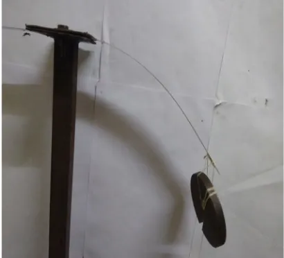
[image:4.612.203.408.514.700.2]In the laboratory, experiment is designed to perform numerical methods present in this paper. Consider a cantilever beam of flexible steel of rectangular cross-section, fixed at one end and free at other end with one concentrated load applied. The beam is fixed to a vertical stand rod by using two nuts and bolts to provide better support. The experimental setup of the beam is shown in Fig. 2. This experiment is performed for the different beam length like L=0.400m, 0.350m, 0.300m, 0.250m, 0.200m, 0.150m, 0.100m, 0.050m. The other measurements of the beam are: width, b=0.0245m, height, h=0.001m, weight, W=0.055kg. Moment of Inertia (M.I.), I=2.042x10⁻¹²m4. At the free end we applied one concentrated load 4.905N for experimental measurement. Assume young’s modulus of elasticity (typical value for steel) E=200x109N/m2.Due to the application of vertical load at the free end of the beam structure the beam will bend. The bending of the beam will be both along the horizontal and vertical directions. The deflections along both the horizontal and vertical directions are measured. The different parameters used in this experiment are listed in the Table I given below. The experimental results from the experiment are listed in Table II.
Technology (IJRASET)
TABLEI: DIFFERENTPARAMETERSOFTHEBEAM
S. No. Parameter Values
1 Load Applied 4.905N
2 Width 0.0245m
3 Height 0.001m
4 Weight 0.055kg
5 M.I. 2.042x10⁻¹²m4
TABLEII:DEFLECTIONOFBEAM(EXPERIMENTAL)
S. No. Length (m) Weight (N) Δx (m) Δy (m)
1 0.050 4.905 0 0
2 0.100 4.905 0 0.004
3 0.150 4.905 0.001 0.015
4 0.200 4.905 0.003 0.034
5 0.250 4.905 0.009 0.062
6 0.300 4.905 0.022 0.099
7 0.350 4.905 0.038 0.147
8 0.400 4.905 0.066 0.200
A. Finite Element Analysis Of The Beam
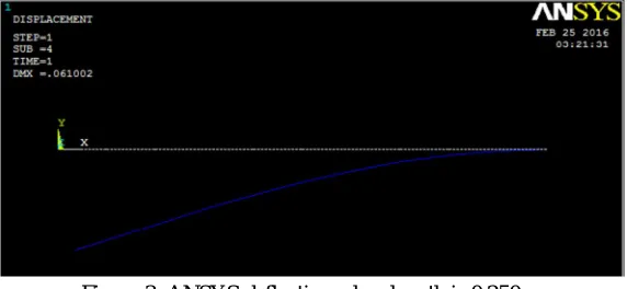
[image:5.612.164.450.415.547.2]To validate the experimental results the finite element analysis of the beam is done using ANSYS 12.0 software. Ten element discretization of the steel cantilever beam is done in ANSYS using Beam 3 element. One end of the beam fixed end a point load is applied at the other end of the beam. The horizontal and vertical free end displacements of the beam are listed in Table III. From Table III it is clear that there is a very close agreement between the experimental results and the ANSYS results. The deflected shape of the beam is shown in Fig. 3.
[image:5.612.71.543.582.722.2]Figure 3: ANSYS deflection when length is 0.250m.
Table III: Experimental and ANSYS results for selected lengths of the beam which will be training data for the ANN
S. No. Length
(m)
Weight (N)
Experimental Deflection ANSYS Deflection % Error
Δx (m) Δy (m) Δx (m) Δy (m) Δx Δy
1 50 4.905 0 0 0 0 0 0
2 100 4.905 0 0.004 0 0.004 0 0
3 150 4.905 0.001 0.015 0.001 0.014 0 6.7
4 200 4.905 0.003 0.034 0.003 0.032 0 5.9
5 250 4.905 0.009 0.062 0.009 0.061 0 1.6
6 300 4.905 0.022 0.099 0.021 0.100 4.5 1.0
7 350 4.905 0.038 0.147 0.039 0.150 2.6 2.0
Technology (IJRASET)
B. Artificial Neural Networking Prediction Of The Deflection
[image:6.612.225.386.519.693.2]The ANN method is one of the most efficient techniques to solve the non linear problems. Therefore in this study the non-linear problem is solved using ANN approach. Variable length of the cantilever beam is considered for the experimental as well as finite element analysis. The results obtained from those experimental and finite element analysis is used to train the neural network. The experimental data are used to train the ANN network. Where eight input are used for training. For training purpose, two tables (i.e., input table and output table) are created in workspace window of MATLAB. In input table, data of variable lengths are considered and in output table data of large deflections of beam in both the horizontal and vertical directions are considered.
Figure 4: ANN Network
In the paper Gaurav et al. [10] predicted the deflection of a cantilever beam for the different loading conditions using ANN technique. In this paper the study is further extended to predict the large deflection of the beam for variable length of the beam. In this study a fixed load is applied at the free end of the cantilever beam to measure the horizontal and vertical deflections of the beam. Now the length of the beam is varied and the same load is applied at the free end of the beam to measure the deflections. This experimentation is performed for some selected lengths of the beam and that is verified through the finite element analysis using ANSYS. These data obtained from those experimental analyses are used to train the neural network. Levenberg-Marquardt technique is applied here to train the network. Now the network can predict the deflection for any intermediate lengths of the beam.
C. Sample Experimental Analysis
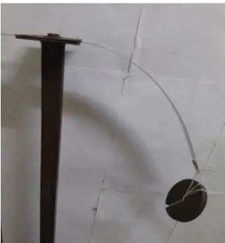
The experimentation is performed for different lengths of the beam. Here the figure 5 shows the experimentation for only one sample length of the beam.
Technology (IJRASET)
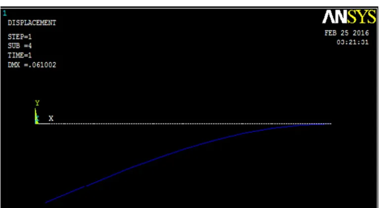
D. Sample Finite Element AnalysisThe finite element analysis of the beam is performed in ANSYS. Variable lengths of the beam are considered for the analysis. Here the figure 6 shows the finite element analysis for a sample length of the beam.
[image:7.612.115.498.122.332.2]Figure 6: ANSYS deflection when length is 0.325m.
Table IV: Predicted deflection from ANN and verified data from ANSYS
S. No. Length
(m)
Weight (N)
ANN Deflection ANSYS Deflection % Error
Δx (m) Δy (m) Δx (m) Δy (m) Δx Δy
1 75 4.905 2.4e-5 1.6e-3 2.3e-5 1.7e-3 4.2 5.8
2 125 4.905 3.7e-4 7.8e-3 3.5e-4 8e-3 5.4 2.5
3 145 4.905 7.5e-4 0.013 6.8e-4 0.013 9.3 0
4 167 4.905 1.4e-3 0.020 1.3e-3 0.020 7.1 0
5 190 4.905 2.5e-3 0.029 2.4e-3 0.028 4.0 3.4
6 230 4.905 5.9e-3 0.046 6e-3 0.048 1.7 4.2
7 260 4.905 0.011 0.064 0.011 0.067 0 4.5
8 325 4.905 0.029 0.122 0.029 0.121 0 0.82
9 365 4.905 0.046 0.160 0.046 0.161 0 0.62
10 395 4.905 0.062 0.192 0.062 0.192 0 0
IV. CONCLUSION
In this study the prediction of the large deflection of cantilever beam is performed for variable lengths of the beam. Artificial Neural Networking technique is applied here to predict the deflection for any arbitrary length of the beam. The results from the analysis clearly prove the efficiency of the network. This soft computation application to solve the large deflection problem of a beam helps to avoid the mathematical complicacy of the non linear equation of geometrical non linearity. The proposed artificial neural network is capable enough to predict the deflection of free end of cantilever beam of any length under the action of a static load at the tip of the beam. Therefore this paper is very effective in the field of non linear deflection of the structures.
REFERENCES
[1] Tarsico Belendez, Cristian Neipp & Augusto Belendez, “Large and Small deflections of cantilever beam”, European Journal of Physics, vol.23, pp. 371-379, May2002.
[2] Kyungwoo Lee, “Large deflections of cantilever beams of non-linear elastic material under a combined loading”, International Journal of Non-linear Mechanics, vol. 37, pp. 439-443, 2002.
Technology (IJRASET)
vol. 32, pp. 692-703, 2005.
[4] A. Banerjee, B. Bhattacharya, A.K. Mallik, “Large deflection of cantilever beam with geometric non-linearity: Analytical and numericsl approaches”, International Journal of Non-linear Mechanics, vol. 43, pp. 366-376, 2008.
[5] Li Chen, “An integral approach for large deflection cantilever beams”, in International Journal of Non-linear Mechanics, vol. 45, pp. 301-305,2010.
[6] E. Solano-Carrillo, “Semi-exact solutions for large deflections of cantilever beams of non-linear elastic behaviour”, International Journal of Non-linear Mechanics, vol. 44, pp. 253-256, 2009.
[7] T. Kocatruk, S.D. Akbas, M. Simsek, “Large Deflection static analysis of a cantilever beam subjected to a point load”, International Journal of Engineering and Applied Science, vol. 2, pp. 1-13, 2010.
[8] R.S. Pawar & S.H. Sawant, “Experimental static Analysis of a Cantilever Beam with Nonlinear Parameters”, International Journal of Engineering Sciences & Research Technology, ISSN: 2277-9655, Sept. 2014.
[9] A. Kimiaeifar, N. Tolou, A. Barari & J.L. Herder, “Large deflection analysis of cantilever beam under end point and distributed loads”, Journal of Chinese Institute of Engineers, vol.37, pp. 438-445, 2014.