6
I
January 2018
Petroleum and Gas Exploration and Production by
Extended Reach Drilling (ERD) Wells
Dr. R. Giri Prasad1, 1
Associate Professor, Dept. of Petroleum Engineering, Aditya Engineering College, hod_pt@aec.edu.in
The term “vertical well” has always been an oxymoron in the petroleum industry. The simple fact, known almost from the advent of drilling, is that all wells deviate at some point from a true vertical line. The more egregious examples of this were referred to as “crooked holes” and it quickly was recognized that wells in certain areas were prone to being crooked holes. Early crooked holes were identified by production engineers who noticed issues with rod wear and geologists who had difficulty correlating formation tops. API’s “Straight Hole Drilling Practice” in the year (Dodge 1929; Lahee 1929), at that time almost all production wells were being planned as vertical wells and drilled with no recorded instances of attempts to control deviation from vertical.
I. WELLBORE DEVIATION
[image:2.612.195.421.416.628.2]Prior to the mid-1920’s, most exploration companies did not quantify the extent of deviation in their wells. Mining companies, particularly diamond miners in South Africa, had been using wellbore surveying techniques beginning in the early 1900’s. However, the use of survey techniques was not common in the oil and gas industry. This began to change as oil companies recognized the issues that arose with unintentionally deviated wellbores. In some cases, operators began putting deviation limits and drilling parameter limits in turnkey contracts in order to control deviation. The reasons for controlling deviation were explained in the first large study of well deviation, conducted by Alex Anderson. The first recorded instance of controlled deviation of a wellbore was in 1928 in the Signal Hill field by John Eastman and the Kuster Company. Kuster The inventor of the technology, actually drilled several planned horizontal wells in the Big Lake Field the following year in 1929.
Fig. 1 - First significant use of directional drilling technology: control of 6000 bop blowout in Conroe Field in 1934(Gleason 1934).
On November 12, 1933 the relief well was spudded and the target was reached on January 7,
of guiding the bit to a desired point as opposed to letting it go where it wanted became more prevalent. In the 1930’s, directional control was accomplished through the use of whip stocks or by controlling drilling parameters, such as weight on the bit, and BHA design.
II. EARLY DIRECTIONAL WELLS
[image:3.612.98.491.221.403.2]Onshore locations were typically located directly above their reservoir targets, but this luxury was not afforded to most offshore wells. As soon as offshore development began, the need for directionally drilled wells in this environment was apparent. The first offshore development in the U.S. was in 1896 in Santa Barbara, CA in the Summerland Field. These wells were drilled from piers that had been built out over the water, sometimes exceeding over1200’ offshore. Early Gulf Coast wells were drilled from barges and were also single well locations.
Fig. 2 - Early directional drilling used when surface location was not directly above target in map view (Bourgoyne et al. 1986).
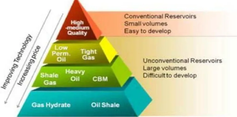
Directional drilling technology continued to gain widespread acceptance both onshore and offshore. For the most part, directional drilling was primarily used to steer a wellbore from a surface location to a point in the reservoir that was hundreds of feet away in the horizontal direction from the surface location (Fig. 2). Several technologies have been the key to exploiting unconventional reservoirs and each has a specific application. One of the primary technologies used to unlock many of the unconventional resources is horizontal drilling.
[image:3.612.117.502.511.701.2]III. HORIZONTAL WELLS
The gains in productivity of those horizontal over vertical wells in the same field ushered in new era of drilling that opened up many previously uneconomic formations by increasing exposure to the pay zone. The economics of drilling a horizontal well in a high permeability reservoir are typically not as attractive as drilling a horizontal well in a low permeability reservoir. The reason for this difference is because the high permeability, or conventional, reservoir will have a large productivity index, and thus, there is no need to increase the exposure of the pay zone by drilling the well horizontally. The result of a horizontal well in a high permeability formation is a decreasing return on investment relative to permeability.
The trend of production volume of the well path types is even more dramatic, as seen in Fig. 4. The monthly production in equivalent barrels attributed to directional and horizontal wells was less than one percent of the total onshore wells in 1956. By 2011, this percentage changed to 64 percent. The production trend is an indirect indication of the increased productivity of directionally drilled wellbores.
IV. GEO-STEERING
A successful directional drilling operation, particularly one involving horizontal drilling, requires an accurately placed wellbore. The real-time process used to steer and place the wellbore is referred to as geo-steering. Geo-steering is defined as:
“The intentional directional control of a well based on the results of down hole geological logging measurements rather than three-dimensional targets in space, usually to keep a directional wellbore within a pay zone. In mature areas, geo steering may be used to keep a wellbore in a particular section of a reservoir to minimize gas or water breakthrough and maximize economic production ....” Based on the definition, this is a seemingly simple task; however, the application of the concept is difficult when undertaken within the tight tolerances of today’s geological targeting requirements. Three elements must be in place in order for a successful geo-steering operation:
A. Geologic and drilling operation experience in the geographic area B. Accurate geologic data prior to drilling (seismic, offset well correlations)
C. Timely and accurate drilling and formation data during the geo-steering operation.
The reality of geo-steering, even in “easy” areas with minimal geological complexity and highquality real-time data is that the wellbores are rarely placed 100% in the desired target window. An individual well may encounter local geological abnormalities as well as difficulty in controlling the well path. The key then to geo-steering is not just the preparation and data analysis but identifying and fixing the inevitable issues and problems which arise.
V. DIRECTIONAL DRILLING TECHNOLOGIES: WHIPSTOCKS
The physical technology used to change the course of the well has progressed from a simple machine (ramp in the form of a whipstock) to tool strings that cost millions of dollars each to manufacturer. Circumstantial reports show 1895 as the first time a whipstock was used (Inglis 1987). It was a simple wedge or ramp dropped down hole to sidetrack a well. While it was used in what we would consider a fishing application to get around junk in the well and the new wellbore’s direction as not controlled, none the less it was the first recorded intentional deflection of a wellbore from its otherwise prescribed path.
Whipstocks were the first tools used to control the well path. The whipstock was simple: a wedge that was run into the wellbore. Once oriented and set in place, a bit was run in the hole and drilled off of the original well path in the direction the whipstock was pointing (Fig. 4a). The process of using a whipstock as shown in Fig. 5, was repeated as many times as necessary. The use of multiple whipstocks was very laborious and took along time to achieve so the driller could maintain the proper trajectory to total depth (TD).
Fig. 5 - Procedure for controlling hole direction with a whipstock. It run into wellbore and oriented in desired direction, allowing deviation to occur(Devereux 1999).
In many wells, the primary goal was just to maintain a vertical wellbore. In this event, the manipulation of the drilling parameters was often used. Drilling parameter manipulation proved to be a useful tool in controlling well deviation but whipstocks remained the primary method of initiating a change in the direction of a wellbore. To avoid the large number of trips involved in drilling with whipstocks or the limited results with parameter manipulation, alternate methods were developed. One of the first methods was jetting. Jetting involved bits specially manufactured or modified to provide an oriented stream of drilling fluid into the wall of the wellbore. The hydraulic energy would erode the wall and the bit and drill string would follow this erosion (Fig.4c).
VI. DIRECTIONAL DRILLING TECHNOLOGIES: MUD MOTORS
The mud motor is a positive displacement pump intended to turn the bit using the flow of drilling fluid. This rotation at the bit is independent of the rotation of the drill string. Mud motor technology developed into its currently recognizable configuration of a positive displacement motor (PDM), or mud motor to use an industry term. By pairing the PDM with a bent sub above it, the directional driller was able to steer much more effectively. The drill string’s rotation would be stopped and the PDM would be oriented in the desired direction using the bent sub similar to Fig. 6b.
[image:5.612.211.379.579.717.2]Steering a well with a PDM involves a series of slide-and-rotate sections known as course lengths. Fig. 9 illustrates the steering (sliding) mode and the straight-drilling(rotate) modes for a conventional bent-housing PDM. Each time the PDM slides ahead, the hole angle and direction change based on the geometry of the PDM. The geometry involved in this process is the three points of contact between the PDM and the hole wall(Fig. 7).
Fig. 7 - PDMs have 3 points of contact while sliding, thus creating an arc-shaped path (Hughes 2009).
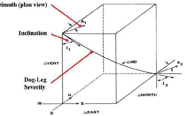
[image:6.612.118.502.454.695.2]Dog-leg severity is the change in direction between two points in the wellbore. There are two dimensional changes in direction, known as azimuth and inclination. Azimuth is the change relative to true North and can be thought of as the change in the well path as seen on a map. Inclination is the change in the well path relative to vertical. A perfectly vertical well has an inclination of zero and a perfectly horizontal well has an inclination of 90 degrees. The dog-leg severity is the rate of three-dimensional angle change and accounts for both azimuth and inclination. These three terms are illustrated in Fig. 8, which shows the well path between two hypothetical survey points.
After the sliding course length, the drill string, and thus the PDM, is rotated. The well path ideally proceeds on a straight path following the direction and angle created by the slide course length. The end result is a well path made up a combination of arcs (from sliding) and tangents (from rotating) as illustrated in Fig. 9.
Fig. 9 - PDMs steer through a series of slides (arcs) and rotations (tangents).
VII. DIRECTIONAL DRILLING TECHNOLOGIES : ROTARY STEERABLE SYSTEMS
This technology is rotary steerable systems (RSS) and is a step change in down hole directional drilling technology. Similar to the bent-sub / PDM eliminating the trips associated with whipstocks, RSS eliminated the need to slide to make course corrections. RSS uses several methods to allow for well path corrections while rotating the drill string. The tool that acts very much like a PDM with a continuously adjusting bent housing. Currently RSS does not consistently produce DLS above 10 deg/100’. As most curves in unconventional wells are drilled at 10 deg/100’ or even higher DLS, applying RSS in this market is difficult. However, as the technology develops and customers demand higher DLS capability, the limits of RSS are continuously changing.
VIII. DIRECTIONAL DRILLING TECHNIQUES
The heterogeneity of the formations being drilled can influence the deviation of the drill string. Steeper dipping formations will keep the bit drilling parallel to the bedding planes, whereas in less steeply dipping formations the bit and the bedding planes will be at a right angle.
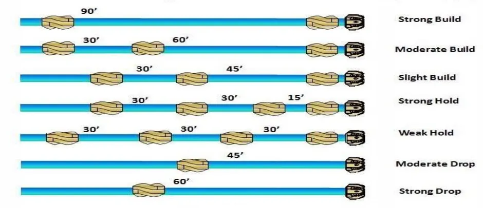
[image:7.612.72.542.500.703.2]The interaction of WOB, Torque and RPM in affecting the well trajectory are well known to the industry as the pendulum effect, where stabilizer placement and point of first hole contact can cause the hole to return to the vertical position or to build/drop angle. Components of the BHA such as drill collars and heavy weight drill pipe (HWDP) can be used to provide more WOB. Generally, increasing WOB will build angle, while a decrease in WOB will drop angle. This is not the best way to cause drops because a reduction in WOB can result in less depth of cut (DOC), which can cause more whirl and thus bit damage. Stabilizer positioning has also been known to help with build/drop angle and how the placement would affect the drill string (if all the other drilling conditions are constant) as illustrated by Fig.10. Stabilizers placed further away from the bit result in drop angle, while placing a stabilizer closer to the bit would help maintain or even build angle.
IX. DIRECTIONAL DRILLING PROCESS
Whether the PDM or the RSS is used, the process and problems involved in the steering decision-making are similar. The primary issue is not with the BHA or steering system itself, it is often with the surveying and logging tools. These tools are typically placed 50 to 70 feet back from the bit. While “near-bit” tools exist for inclination and gamma ray, these result in added cost while still not giving all of the necessary data. In particular, the near-bit inclination is not considered to be a viable substitute for the full MWD survey tool further up the BHA.
The result of this tool placement is that at the last known location in the wellbore, as measured by the survey tool, there will always exist 50 or more feet of unknown wellbore ahead of it. Within this 50 feet, multiple slide-rotate course lengths (for PDMs) or steering strength changes (for RSS) may exist. Lithology will likely have changed to come extent as well, even in a horizontal wellbore. Therefore, in order to accurately drill ahead in a manner which keeps the wellbore in zone, assumptions must be as what the outcomes of these steering actions were. This leaves the directional driller making a constant series of educated guesses concerning what his recent steering actions did with regards to wellbore direction and what he should do as he drills ahead. If the directional driller makes a poor assumption regarding the outcome of his decision, the result either a wellbore drilled out of zone or additional time spent steering the wellbore back onto the desired path.
X. DRILLING AUTOMATION
In recent years, drilling automation has advanced from being mostly related to rig floor equipment to an idea that is applied to all parts of the drilling process. This expanding focus has occurred through the confluence of increased safety concerns, larger amounts of high quality, real-time data becoming available and high oil prices which provide the funding to develop a more automated drilling process. Overall, the term “drilling automation” is trending toward the optimization of performance. Theoretically, the ability to control a well is based on the geometric relationship between the BHA and the wellbore.
However, as the technologies were implemented, engineers immediately saw how significant time and cost savings could be found through automation in addition to the obvious safety benefits. A visit in any rig manufacturing facility today will bear this out. The safety aspect alone does not explain the widespread use of rig floor automation equipment. The majority of the newbuild land rigs in market incorporate most, if not all of these pipe-handling features because customers are willing to pay for them. The customers are willing to pay extra not only because of an increased focus on safety but also due to the recognition of the economic benefits of rig automation.
XI. CONCLUSION
REFERENCES
[1] Adam T, B. J. (1991). Applied Drilling Engineering (Vol. 2). Richardson, Texas: Society of Petroleum Engineers [2] AIMR (Azimuth And Inclination Modeling In Realtime): A Method For Prediction Of Dog-Leg
[3] Severity Based On Mechanical Specific Energy. A Dissertation by Samuel Frans Noynaert, [4] Submitted to the Office of Graduate Studies of Texas A&M University 2013
[5] Aldred, W.D., Belaskie, J., Isangulov, R. et al. 2005. Changing the Way We Drill. [6] Schlumberger Oilfield Review, March 1, 2005, 8.