Implementation of IEEE 802.15.4 PHY Using
Matlab
Blessy s
School Of Engineering, Cochin University Of Science And Technology
Abstract— IEEE802.15.4 is a standard which specifies the physical and medium access control for low rate, cost, low-power Wireless Personal Area Networks (LR-WPANs).This paper aim to develop a mat lab model for IEEE 802.15.4 physical layer and plot the bit error rate curve while the transmission done in different environment.
Keywords— IEEE 802.15.4, mat lab, bit error rate, physical layer, oqpsk, Rayleigh, racian
I. INTRODUCTION
Why do we go for research? The answer is ‘to enhance human life’. From a low level life to a ‘anywhere any time ’connected life is the contribution of these researches. Everything in a fingertip is the advantage of engineering and technology. Wireless communication is one of the big success stories in the field of engineering in terms of scientific point of view as well as impact on society. Now the wireless industry is dominating the world economy. Living habits especially the way we communicate have been changed dramatically as ‘anywhere any time’ talking.
There are different classes of wireless communication. Wireless sensor network (WSN) is a main class among that. WSN finds number of applications to monitor physical or environment conditions such as temperature, pressure, sound etc by pass information gathered to a main location or a coordinator.
Different standards are designed for WSN. IEEE 802.15.4 is a standard uniquely designed for low rate personal area networks. The standard offers device level connectivity and it target low data rate, low power consumption and low cost. This paper aims to develop an end to end model of physical layer of this standard in MATLAB using Monte Carlo estimation.
II. OVERVIEWOFIEEE802.15.4
IEEE 802.15.4 defines the protocol and interconnection of devices via radio communication in a personal area network (PAN). [1].The standard uses carrier sense multiple access with a collision avoidance medium access mechanism and supports star as well as peer-to-peer topologies.[2]
A. General description
Large numbers of researches are going on in wireless sensor networks. The standards define for WSN should meet the criteria such as low rate ,low power and energy efficient .As the nodes are very tiny units and are driven by battery, it is certain that the standard for WSN is low power consuming. Wireless sensor network has great application in industrial and home automation. IEEE 802.15 .4 is a suitable standard for low rate personal area network such as wireless sensor networks due to its low complexity and low power consumption. The standard define 2 lower levels of OSI; physical layer (PHY) and medium access control(MAC) layer. Rest of the layers are defined by Zigbee alliance. That’s why the two terms are used interchange.
There are large number of works performed in zigbee using matlab simulink, NS2, OPNET [7][8].This present the modelling of PHY of IEEE 802.15.4 using matlab coding. Along with the basic model, paper investigates modifications in reciever for various channel conditions because the network works in a noisy environment containing large attenuating properties.
III. PHYSICALLAYER
A. Services
The PHY provides two services:
1) PHY Data Service: The PHY data service enables the transmission and reception of PHY protocol data units (PPDUs) across the physical radio. channel The features of the PHY are activation and deactivation of the radio transceiver, energy detection, link quality indication, channel selection, clear channel assessment (CCA), and transmitting as well as receiving packets across the physical medium. [4]
2) PHY Management Service
The radio shall operate at one of the license-free bands: 868–868.6 MHz (e.g., Europe), 902–928 MHz (e.g., North America) or 2400–2483.5 MHz (worldwide). [6]
B. Physical Layer: Modelling
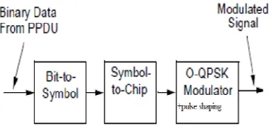
[image:3.612.213.408.252.348.2]The paper only concentrates for physical layer. Fig 1 shows Block diagram of IEEE 802.15.4 physical layer.
Fig. 1.model of physical layer.
1) Bit to Symbol Mapping: This block showing how binary information is mapped into data symbols. The 4 LSBs (m1,m2,m3,m4) is mapped into one data symbol, and the 4 MSBs (m5,m6,m7,m8) of each octet shall map into the next data symbol.[4]
Physical layer data frame contain physical service data unit (PSDU) whose maximum length is 127 octets ie 1016 bit .Now this block convert 1016 bit to divide by 4 size.ie to 254.if the synchronisation header and frame length block there then the size wil be 266.Synchronization Header The synchronization header (SHR) consists of the preamble sequence followed by the start of frame delimiter (SFD). In the IEEE 802.15.4 specification the preamble sequence is defined to be 4 bytes of 0x00. The SFD is one byte with value 0xA7. The frame length field is 7 bits long .Themost significant bit in the length field is reserved, and should always be set to zero.[6]
2) Symbol-to-chip mapping: Each data symbol shall be mapped into a 32-chip PN sequence as specified in TABLE I[6]. 3) Synthesis of chip sequence: Chip sequence for zero symbol is given here.
seq=[1 1 0 1 1 0 0 1 1 1 0 0 0 0 1 1 0 1 0 1 0 0 1 0 0 0 1 0 1 1 1 0]
Convert it into I and Q branch data by collecting even and odd indexed data. seqI=seq(1:2:end) %even indexed
seqQ=seq(2:2:end)%odd indexed
Chip sequence for 1 st and 9 th symbol are produce by the following commands. x=[1 0 0 0] %1-symbol
yI=circshift(seqI,[0 2]) yQ=circshift(seqQ,[0 2]) x==[1 0 0 1] %9-symbol yI=circshift(seqI,[0 2]) yQ=~circshift(seqQ,[0 2])
likewise all other symbols are produced.
TABLE II CHIP SEQUENCE
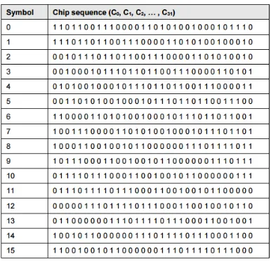
IV. BERCOMPARISIONOFVARIOUSSTANDARDS
Fig 2 shows the plot for ber comparison of various ieee standards.Plot shows the IEEE 802.15.4 is the minimum ber standard .I use the following matlab command to plot the ber of ieee 802.15.4
SINR = -10:20; % SINR in dB
sinrp = 10.^(SINR./10); % SINR in linear power for sinr_cnt=1:length(SINR)
BER_15_4_temp =0; for k=2:16
part_temp = (-1)^(k) * (factorial(16)/factorial(k)/factorial(16-k)) * exp(20*sinrp(sinr_cnt)*((1/k)-1)); BER_15_4_temp = BER_15_4_temp + part_temp; % BER for 802.15.4 DSSS 250kbps
end
BER_15_4(sinr_cnt) = (8/15) * (1/16) * BER_15_4_temp; end
FER_15_4 = 1-((1-BER_15_4).^L_15_4); % FER for 802.15.4 DSSS 250kbps
V. SIMULATION
CC2520 2.4 ghz ieee 802.15.4 RF transceiver [5] is used to carry out a special test known as spin table test. There is a table which is rotating at a speed of 1 revolution per second. So that the table can obtain an angular acceleration of ωr2.A transmitter is placed on the table and the receiver is placed at a distance 4m from table. At receiver there is a low noise amplifier. As per the specifications of CC2520 sensitivity of module is -98dbm and power is 5dbm.But actually the power is 3dbm.Low noise amplifier has a sensitivity of -6dbm.Total sensitivity of receiver is -104.Fig 3 shows the problem description.
Transmitter transmits 512 packets in 2 minutes. Each packet has 128 bytes. While doing this got a sensitivity curve shown in fig 4. When doing the test error occurs at burst errors. Theory says if the receiver diversity is below -104 dbm then only the error occur. By the test, if the sensitivity is below -70dbm here will be errors. Due to the errors are not random, we cannot apply convolutional codes. Block codes can be apply as the errors are burst.The errors can be reduced by employing forward error correction apply diversity
Error correction throgh code is an effective method. Apply RS code for this senerio. Diversity is another technique. Different diversity techniques are here. In this senerio 3 diversity methods employed
A. Spatial diversity
If we design to work two cells in 2 frequency then we can obtain frequency diversity.
Fig. 2 .ber comparison
Fig.3.test description
[image:5.612.122.515.105.324.2]VI. ALGORITHM
Implementing Monte Carlo method to plot physical layer of IEEE 802.15.4 A. Start of simulation
B. Set number of packet transmitting and the iterations.
C. Generate data frame for transmission over network using basing physical data format D. Convert bit to data symbol and then data symbols into chip sequence
E. Modulate the chip sequence with Offset Quadrature Phase Shift Keying and half sine pulse shaping F. Generate noises which is being added during
G. Transmission through channel
H. Transmit signal through channel and add generated noise
I. Demodulation
J. Find errors
K. Continue for all values of packet transmitting and the itrations dor all values of snr
Fig.5.ber plot
Fig.6.ber plot in different environment
Wild points can be avoid by increasing the iterations. Ber resolution can be increased by increasing number of packets. Fig 8 show awgn channel response with bpsk and fig 9 shows awgn and Rayleigh channel simulation.
VII. CONCLUSION
REFERENCES
[1] IEEE P802.15.4/D18, Draft Standard: Low Rate Wireless Personal Area Networks, Feb. 2003.
[2] Tarjei Aaberge,”Low Complexity Antenna Diversity For IEEE 802.15.4 2.4 GHz PHY”
[3] Zheng and Lee,”A comprehensive perfomance study of ieee 802.15.4”
[4] Salman,Rasool and Kemp,”Overview of ieee 802.15.4 standard family for low rate wireless personal are network”,IEEE 2010
[5] CC2520 DATASHEET
[6] Wireless Medium Access Control (MAC) and Physical Layer (PHY) Specifications for Low-Rate WirelessPersonal Area Networks (LR-WPANs), IEEE
Computer Society Eirini Karapistoli and Fotini-Niovi Pavlidou
[7] K. Shuaib and I. Jawhar M. Alnuaimi, "Performance Evaluation of IEEE 802.15.4 Physical Layer Using Matlab/Simulink," in Innovations in information technology, Nov 2006., pp. 1-5.
[8] Scolari N and Enz C.C., "Digital receiver architectures for the IEEE 802.15.4 standard," in ISCAS '04. Proceedings of the 2004 International Symposium on Circuits and Systems, vol. 4, 2004, pp. 345-348.
[9] Andreas F. Molisch, Kannan Balakrishnan, Dajana Cassioli, Chia-Chin Chong, Shahriar Emami, Andrew Fort,Johan Karedal, Juergen Kunisch, Hans Schantz, Ulrich Schuster, Kai Siwiak’” IEEE 802.15.4a channel model”
![Is there a Link between Profit Share Rate of Participation Banks and Interest Rate?[:] The Case of Turkey](data:image/gif;base64,R0lGODlhAQABAIAAAP///wAAACH5BAEAAAAALAAAAAABAAEAAAICRAEAOw==)