2019 International Conference on Computational Modeling, Simulation and Optimization (CMSO 2019) ISBN: 978-1-60595-659-6
Enterprise Network SDN Solution Research
Jian-feng JIANG
Suzhou Industrial Park Institute of Services Outsourcing, China, 215123
Keywords: SDN, Enterprise network, Network construction.
Abstract. With the continuous development of network technology, the traditional network of distributed control architecture reflects the shortcomings gradually. After collecting the network topology with the network devices each time, you need to run a large number of routing protocols to calculate routes, generate a routing table in order to forward data. It is need to configure a large number of agreements instead of using the network devices to run the same algorithm, and then to avoid the device loop. This topic introduces the network reconfiguration method based on the new network architecture SDN (software defined network) technology during the entire process of network design. It makes the enterprise network safe, stable and easy to maintain with the new technology.
Introduction
In traditional network architectures, data forwarding and control of network devices rely on a large number of protocols. The network administrator needs to modify a large number of network devices when an enterprise's business needs change, such as switches and routers. The network will always face congestion problems to adapt to new business needs, because the company's network bandwidth is limited. The SDN[1] technology separates the control planes of an enterprise's network control by a unified controller, and then delivers them to the data plane and forwards them by the data plane. In the face of network changes, network administrators only need to make corresponding changes at the control level, and then send them to the data layer, which not only simplifies the configuration of the network, but also improves the performance of the network to some extent.
SDN Network Architecture
SDN Three-tier Model of Network Architecture
In the entire SDN network architecture[2], there are three levels: the collaborative application layer, the control layer, and the forwarding layer. The traditional network architecture itself consists of three levels: management plane, control plane and forwarding plane. The three levels of SDN just correspond to it.
The main purpose of the collaborative application layer is to complete the user's various upper-layer applications, such as OSS, which can be responsible for business collaboration across the network. Openstack is responsible for computing, and storage collaboration in the data center.
The control layer is the core part of the whole SDN. The implementation entity of this layer is the SDN controller, which is responsible for the internal switching path of the network and the generation of border service routes. When the network status changes, the control layer will adjust the internal switching path and service routing of the network.
SDN Three Interfaces of the Network Architecture
The core of the SDN network architecture is the SDN controller at the control layer[3-4]. It consists of three interfaces: the northbound interface (NBI), the southbound interface (SBI), and the east-west interface.
The NBI interface is similar to the management interface in the traditional network. It is an interface connected to the collaborative application layer. The main job of the interface is to provide service management such as deployment virtualization services.
The SBI interface is mainly used between the controller and the repeater. On one hand, the controller can send the flow table to the forwarding layer through the interface. On the other hand, the forwarding layer can upload a variety of information collected from the devices such as network topology information and alarm information.
The east-west interface is mainly used to interconnect with other networks, especially traditional networks. At present, this interface is not fully popularized in the SDN solution. In most operators and enterprise networks, large-scale traditional networks are still deployed.
SDN Plan Design
RG-ONC is an SDN controller based on RG-ONP of Ruijie Intelligent Open Network Platform[5]. Fully compliant with the SDN philosophy, the platform advocates openness, virtualization and intelligence. With the modular technology architecture of java OSGi, it can be upgraded online and compatible with multiple versions while satisfying scalability.
Network Architecture
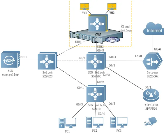
The network solution is established through the SDN core switch, and the traffic is uniformly processed and managed through the SDN controller. The network topology is shown in Fig. 1.
SDN controller
SDN Switch S2910 SDN Switch
S5750C
Gateway EG2000K
PC1 PC2 PC3 Cloud platform
G0/1
G0/3
G0/4 LAN0 ETH1
G0/1 G0/2
G0/3 G0/5
WAN0
Switch S2952G
wireless APAP520 G0/4
OVS VM1 VM2
G0/1
ETH2
[image:2.595.154.436.425.656.2]G0/2 G0/5 ETH1
Figure 1. Network architecture.
IP Address Planning
Table 1. IP address planning.
Devices/Management Interface IP address Remarks
Exit Gateway
GI0/0 10.10.1.1/30
GI0/1 200.200.200.1/30
Loopback 1.1.1.1/32
SDN core switch
vlan10 172.16.0.254/24 Cloud platform public
vlan20 172.16.1.254/24 Wireless user
vlan30 172.16.2.254/24 Wired user
vlan100 10.10.1.2/30 Interconnected
gateway
Wireless AP GI0/0 172.16.1.253/24
Table 2. Core network IP.
Features Device Interface IP Address
SDN management network
SDN Core switch GI0/1 192.168.1.1/24
SDN Access switch GI0/1 192.168.1.3/24
Cloud Server ETH1 192.168.1.4/24
SDN controller ETH1 192.168.1.2/24
SDN Solution Configuration and Implementation
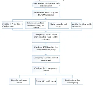
The collective process of SDN solution design is shown in Fig. 2.
Mininet build and docking with RG-ONC controller SDN Solution configuration and
implementation
Configuring network device interconnection based on SDN
technology
Configure SDN-based service access restriction policy
Configure the egress gateway device S t a t i c I P a d d r e s s
Configuration
Configuring a wireless network environment Establish a simulated network topology by
Mininet
Ruijie controller web access
V e r i f y t he fl o w t ab l e information
Open the web-server
service Enable ARP traffic attack
[image:3.595.83.515.87.303.2]Configuring a flow control policy
Figure 2. SDN solution design.
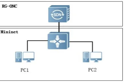
Controller Docking
[image:3.595.136.455.352.645.2]Figure 3. SDN Architecture.
The specific steps include: Static IP address configuration-> Connected controller->Establishing a simulated network topology using Mininet-> Controller web access-> Verify flow table information.
SDN-based Network Device Interconnection
First, ensure that the wireless device can access the IP address 1.1.1.1 through the AP520, and then send the flow table so that each PC can access the IP address 1.1.1.1 normally. The configuration file is shown in Figure 4.
Figure 4. Release flow table.
SDN-based Business Access Strategy
Configure the ARP information entry between PC1 and PC2 through the SDN controller, and send two flow tables on S2910 with a priority of 600 (higher than the arp flow table in the previous requirement). The packet from the GI0/3 and the source mac is the MAC address of the PC1 is transmitted from GI0/4, so that the packet from the GI0/4 and the source mac is the MAC address of the PC2 is transmitted from the GI0/3.
Then, two flow tables are sent in S2910 with priority 500. So that the flow from GI0/3, source ip is 172.16.2.1/32 and the destination ip is 172.16.2.2/32. It is transmitted from GI0/4. The stream from GI0/4, the source ip is 172.16.2.2/32, and the destination ip is 172.16.2.1/32 is transmitted from GI0/3.
Wireless Network Environment
At first, AP should be configured to work in FAT mode with the SSID as rubi-X at broadcast status. Then Set the network with the SSID ruijie-X to perform encryption authentication based on WPA2 and set the authentication password. Finally, the AP's DHCP option is enabled to assign wireless users an address in the range of 172.16.1.100-172.16.1.200 and configure ARP spoofing defense in the wireless environment to prevent ARP spoofing inside the LAN.
RG-S2910(config)# of controller-ip 192.168.1.2 interface gigabitethernet 0/1 RG-S2910#show of
Version:openflow1.3,controller[0]:tcp:192.168.1.2 port 6653 interface gigabitethernet0/1,main is connected,aux is disable,role is master.
Current controller mode : multiple.
external network is 5000Kbps per user, and the total ftp traffic on the internal network does not exceed 100M. Specific steps are as follows: Open the web-server service-> Enable ARP traffic attack-> Configuring a flow control policy.
Result Analysis
The result of the terminal is as shown in Fig .5. The flow table releases the CIMP packets between the hosts and the packets are sent without packet loss.
Figure 5. Communication test.
Conclusion
After the introduction of the new technology SDN, the overall network architecture of the enterprise has changed. Compared with the original traditional network, the maintenance and update of the network becomes faster, and the task of the network administrator becomes relatively easy. Under the basic premise of satisfying customer needs, the working pressure of network equipment becomes smaller, and the forwarding efficiency of data streams is improved.
Acknowledgement
This research was financially supported by the Jiangsu philosophy and social science project (2019SJA1310). Jiangsu Province Higher Education Teaching project (2017JSJG081). School-level teaching reform project (JG-201901). Jiangsu University Student Innovation Project (201914295011Y).
References
[1] Yang, Y.; Jiahai, Y.; Donghong, Q. Multipath routing algorithm for data center networks. Journal of Tsinghua University (Science and Technology, v 56, n 3, pp. 262-268, 2016.
[2] Kobo, H.I, Abu-Mahfouz, A.M, Hancke, G.P. SDN-based application framework for wireless sensor and actor networks open access. IEEE access, v 5, pp. 1583-1594, 2016.
[3] Bannour, F, Souihi, S, Mellouk, A. Distributed SDN control: Survey, taxonomy and challenges. IEEE Trans. Commun, v 20, n 1, p 333-354, 2017.
[4] Iqbal, A, Javedi, U, Saleh, S, Kim, J. Alowibdi, J.S.; Ilyas, M.U. Analytical modeling of endto-end delay in openflow based networks. IEEE access, v 5, pp. 6859-6871, 2016.