2017 2nd International Conference on Computer Engineering, Information Science and Internet Technology (CII 2017) ISBN: 978-1-60595-504-9
A DPLL-based High-Concurrent SAT
Solver with FPGA
LVYING YU, YI ZUO, CAIHONG LI and ANPING HE
ABSTRACT
The SAT problem is one of the most famous NP problems in the theoretical studies of computer science that has been applied in a number of areas, such as artificial intelligence and emulation; and then its high efficient solver, both software and hardware, drives both the study and application of SAT problem. It is well known that the hardware-based solution of SAT solver is capacitated by the high speed, but the design complexity and long chain flow refuse researcher’s enthusiasm. In this article, we propose a FPGA-based SAT solver.
INTRODUCTION
In computer science and artificial intelligence, the Boolean Satisfiability Problem (Sometimes called SAT) is a famous problem that has been proved to be NP-complete [1]. SAT is applied in the field of logical reasoning, design of computer system structure, model detection, integrated circuit design and artificial intelligence [2-4].
At present, the research on the SAT problem mainly focuses on the software solution method in the world, such as [5]. The annual SAT International Competition [6] participating solver is almost all software. In utility system, when the number of variables contained in the formula is increasing, the correlation between the variables is getting stronger and stronger in the real problem, meanwhile it is difficult for the software solver of SAT to cope with the challenges above. In this project, Field Programmable Gate Array (FPGA) technology is used to solve the SAT problem. In recent years, the FPGA has developed rapidly, and the FPGA chip has been developed with the scale of gate scale. The computing power is enough to deal with the actual SAT application. Therefore, using FPGA technology to develop SAT dedicated hardware chip can not only solve the SAT problem quickly and efficiently, but also save the cost of printing and manufacturing chips. It is a cheap, efficient and practical project.
However, a number of SAT hardware solvers have been occurred in the world. These solvers have chosen FPGA as a hardware implementation platform. The vast majority of the existing SAT hardware solver’s method is application, such as [7]. Essentially, the method is a hardware implementation of the software SAT algorithm, using FPGA to achieve some bottleneck algorithm and the final solver work in hardware and software collaboration mechanism. The advantage of this approach is versatility, that is, only compile and configure a process, and then you can calculate all _________________________________________
the examples. But the disadvantage of this approach is that the solution does not essentially introduce the characteristics of the circuit system into the SAT solution. It only uses the programmable features of the FPGA, so this solution will still face the same challenges as the software solver do. Another way is so-called case-like methods, such as [8]. The idea is to develop and configure a chip for each SAT instance, and then give the power to the chip to calculate the satisfaction of the SAT problem. Comparing with the application method, the method is less versatile and costly, but it fully exerts inherent characteristics of the digital circuit system, and completely avoids the challenges of the software and application above. This method is applicable to large-scale SAT instance.
This paper presents a SAT solver system of case-like method. The system is mainly designed for real systems of large-scale CNF formula, and it can be automatically customized to compile and convert to FPGA chips, then the SAT satisfying process of the system is completed by FPGA hardware. Based on previous research results, this paper aims to develop an algorithm for solving SAT problem by bivariate concurrency and conflict handling mechanism.
ARCHITECTURE OF THE SOLVER
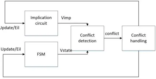
[image:2.612.152.457.379.533.2]In this paper, our solver is mainly composed of four parts, that is: Implication circuit module, FSM module, conflict detection module and conflict processing module. The architecture of the solver is shown in Figure 1.
Figure 1. The architecture of the solver.
Multivariate concurrency SAT solver
THE VARIABLES CHOOSE THE STATE MACHINE
Each variable has two possible values, that is, 0 and 1. In order to allow each variable randomly select a value when assigning each variable, we have written two different state machines, that is, FSM1 and FSM0. If a variable chooses the FSM1, when the variable is assigned, the variable will be assigned a value of 1 firstly. Similarly, if a variable chooses the FSM0, the variable will be assigned a value of 0 firstly. Different assignment of each variable may lead to different implicit values of other variables, which can lead to the difference of solving time. For example, in the following CNF formula (a ∨ ¬ b) ∧ (a∨c) ∧ (a ∨ d). If the variable a chooses the FSM1, when the variable a is assigned, the variable a will be assigned value 1 firstly. When the variable a is assigned value 1, other variables would not be given by its implied circuit to the corresponding implied value, which need to assign by FSM. If the variable a chooses the FSM0, the variable a will be assigned value 0 firstly. When the variable a is assigned value 0, other variables, that is, b c d, will be given implied value by its implied circuit, the solution time will be shorter than the variable choose FSM1.
STATE MACHINE
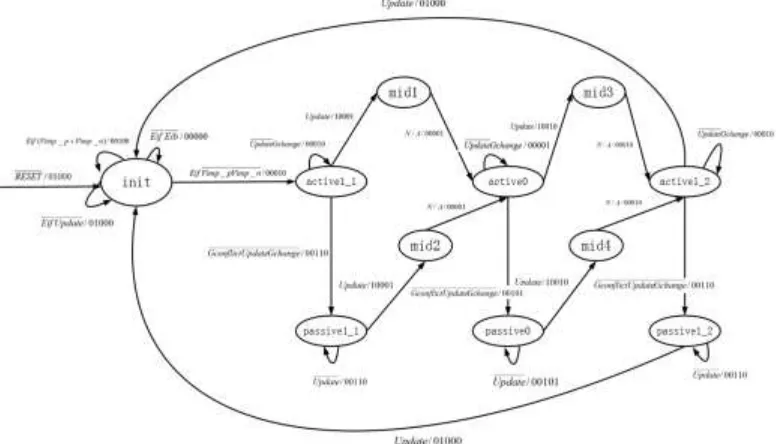
Figure 2 shows the state diagram for every variable, our FSM circuit contains eleven states and five outputs. The input Eif is transmitted from the output Eof of the Synchronize mechanism of the previous two variables. The input Update is transmitted from the output Update of the corresponding conflict handling machine. The input signals Vimply_n and Vimply_p are mapped by the correspondingly implied circuit modules, and they correspond to a_n_i and a_i of the Conflict detection circuit module, respectively. The input Gchange comes from the Conflict detection circuit module.
After initializing, all FSMs will enter the init state, if the input Eif is 1, which means the FSM starts working, the FSM will check whether the variable has been implied, that is, the value of Vimply_p or Vimply_n is 1. If one value of Vimply_p or Vimply_n is 1, the FSM will output Eof=1, which means the variable is solved. On the contrary, the FSM will assign value to the variable, and it will enter the active0_1 state when the next clock arrives, which means the variable is attempted to assign value 0. If the FSM in the active 0_1 state, the conflict is found, which means the assignment of the variable can’t satisfy some clause. The variable will try to assign the other value, so the FSM of the variable will enter the state active1 when the next clock arrives. If a FSM in the active X state, Update, Gconflict and Gchange are 0, the FSM will enter passiveX state. The FSM will output that Eof=1, which means that the assignment to this variable is finished. When a FSM in state activeX, if the FSM’s input is that Update=0 and Gchange=1, the FSM will keep in the state when the next clock arrives. If a FSM in state passiveX, when the FSM receive the input Update=1, the FSM will reassign the variable.
CONFLICT HANDLING MECHANISMS
[image:4.612.99.487.281.503.2]When assigning multiple variables at the same time, it may cause assignment conflicts appear in multiple variables. Therefore, a conflict handling mechanism is needed to control the FSM circuit of the corresponding variable, and it makes the value of the variable change. The conflict handling mechanism is made up of conflict control circuit and conflict enable module. When the conflict enable circuit module output enable=1, the conflict control circuit can work. Figure 3 shows the state transition graphs of the conflict circuit. The input of conflict control circuit is Gconflict, whose outputs are Update1, Update2 and Back. The outputs Update1 and Update2 are transmitted to the Update input of the corresponding variable’s FSM circuit. If Update is 1, the value of variable will change. The inputs of conflict enable circuit are Eif, Eof, Eob1, Eob2, which are connected with the port of the corresponding FSM circuit. The input Back_next is connected with the output Back of the next conflict control circuit. Figure 4 shows the graph of the conflict enable circuit.
Figure 2. The state diagram for the FSM of every variable.
[image:4.612.112.474.538.605.2][image:5.612.100.497.88.401.2]
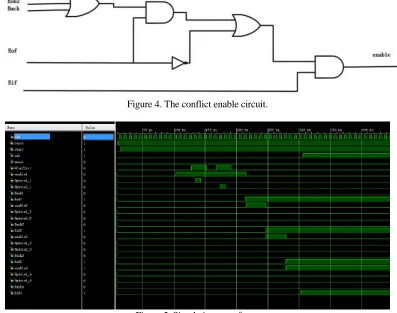
Figure 4. The conflict enable circuit.
Figure 5. Simulation waveform.
SYNCHRONIZE
In our solver, the synchronization mechanism ensures that the two variables are assigned at the same time. The input signals Eif1 and Eif2 are from the output Eof of FSM of the current two variables, and the output signal Eof is enable signal of FSM of the next two variables (Eif). Only when the two variables finishes to assign value, the system will assign the next two variables, so Eif1 and Eif2 are connected with AND gate.
SIMULATION IMPLEMENTATION
Figure 5 is a simulation waveform of two-variable parallel solution algorithm based on FPGA, this problem is a sat problem of 8 variables and 8 clauses.
CONCLUSION
handling circuit module are used to detect conflict, handling conflict, forward and backward distribution variable. Finally, the unsaturated signal connects the different LED to capture the eyes of the observer.
Compared with the previous univariate SAT solver, the throughput of the whole circuit is improved, which effectively improves the solution speed.
ACKNOWLEDGEMENTS
Corresponding author is Anping He. [email protected]. Lanzhou University, Lanzhou, GanSu, China.
This work is support by the Chinese NSF NO. 61402121, the Fundamental Research Funds for the Central Universities of Lanzhou University, No. 861914, and Guangxi Science and Technology Project (AB17129012), the Key Science and Technology Foundation of Gansu Province (No.1102FKDA010) and Guangxi Higher School Key Laboratory of Complex Systems and Intelligent Computing (No.2016CSCI05).
REFERENCES
1. Rod8 Howell SAT-CNF Is NP-complete,
http://www.cis.ksu.edu/Ehowell/F775f00/Fhandouts/sat.ps
2. John D. Davis, Zhangxi Tan, Fang Yu, and Lintao Zhang. Designing an Efficient Hardware
Implication accelerator for SAT Solving[C]. International Conference on Theory and Applications of Satisfiability Testing (SAT), 2008:48-62.
3. Hubie Chen. An Algorithm for SAT above the Threshold[C].International Conference on Theory
and Applications of Satisfiability Testing (SAT), 2003:14-24.
4. Jia Hui Liang (B), Vijay Ganesh, Pascal Poupart, and Krzysztof Czarnecki. Learning Rate Based
Branching Heuristic for SAT Solvers[C]. International Conference on Theory and Applications of Satisfiability Testing (SAT), 2016:123-140.
5. Zhou Jin, Zhao Xishun. A Summary of SAT Algorithm Based on Hardware Programmable Logic
(FPGA) [J]. Electronic World. 2012 (06): 61-69.
6. http://www.satcompetition.org
7. J.T.De.Sousa, J.P. Marques-Silva, M. Abramovici, A Configware/Software Approach to SAT
Solving, Proc. Ninth IEEE Int Symp[C]. Field-Programmable Custom Computing Machines (FCCM’01), 2001.
8. P. Zhong, M. Martonosi, P. Ashar, S. Malik, Using Configurable Computing to Accelerate